Table of Contents
Advertisement
Advertisement
Table of Contents

Related Manuals for John Bean B 1200P


Summary of Contents for John Bean B 1200P
- Page 1 B 1200P...
- Page 2 Todas as informações contidas neste manual foram fornecidas pelo produtor da máquina: Snap-on Equipment Srl a unico socio Via Provinciale per Carpi, 33 42015 CORREGGIO (RE) ITALY Tel.: +39-(0)522-733480 Fax: +39-(0)522-733479 IMPORTANT !! SAVE THESE INSTRUCTIONS - DO NOT DISCARD !! E-mail: corrcs@snapon.com Internet: http://www.snapon-equipment.eu John Bean B 1200P...
- Page 3 DECLARATION CE DECLARACIÓN CE lenses, they are NOT safety glasses. ДЕКЛАРАЦИЯ ЕС DECLARAÇÃO CE Wiring Diagram Balancer is for indoor use only. Schema Elettrico Schaltplan Esquema Eléctrico Schéma électrique Esquema Eléctrico Схема электрических соединений SAVE THESE INSTRUCTIONS John Bean B 1200P...
-
Page 4: Table Of Contents
DISCLAIMER OF WARRANTIES UPDATING REPORTS AND LIMITATIONS OF LIABILITIES While the authors have taken care in the preparation Release D - ________________ - August 2020 of this manual, nothing contained herein: Software reviewing - modifies or alters in any way the standard terms and conditions of the purchase, lease or rental agreement under the terms of which the equipment to which this manual relates was... -
Page 5: Vencimiento De La Garantía
LIMITES D’APPLICATION DE LA GARANTIE ET VENCIMIENTO DE LA GARANTíA Y LIMITATIONS DE LA GARANTIE LIMITACIONES DE RESPONSABILIDAD Bien que les auteurs aient accordé la plus grande A pesar de que los autores han prestado la máxima attention à la rédaction du présent manuel, aucun atención al redactar este manual, se señala que el élément figurant dans ce dernier: contenido del mismo:... -
Page 6: Safety
Safety Safety Important safety precautions relevant to the unit are described in the Safety Booklet, refer to Figure 1-1. The Safety Precautions should be fully understood and observed by every operator. We suggest you store (a copy) of the Safety Booklet near the unit, within easy reach of the operator. -
Page 7: Seguridad
Sécurité Seguridad Sécurité Seguridad Les mesures de sécurité importantes relatives à l’unité En el Manual de Seguridad se describen todas las sont décrites dans le Livret de Sécurité et résumées precauciones importantes de seguridad relativas a la Fig.1-1. unidad, consultar la Figura 1-1. Las Precauciones de Seguridad deberán ser Chaque opérateur doit totalement comprendre les entendidas totalmente por el operador. -
Page 8: Specifications
Specifications 2.0 Specifications Wheel Balancers specs B 1200P B 1200P Cars, light trucks, SUVs Cars, light trucks, SUVs Vehicles supported < 200 rpm Measuring speed < 200 rpm 0.035 oz (1 g) Balancing accuracy 1 g (0.035 oz) 0.7° Angular resolution 0.7° 1.57 inch (40 mm) Diameter of shaft ... -
Page 9: Especificaciones
Specifications Especificaciones 2.0 Specifications Especificaciones Données Equilibreuses Especificaciones equilibrador Véhicules compatibles Vehículos soportados Vitesse de mesure Velocidad de medición Précision d'équilibrage Precisión de equilibrado Résolution angulaire Resolución angular Diamètre arbre Diámetro del árbol Longueur arbre Longitud del árbol Offset bride équilibreuse Offset equilibrador de brida Temps d'équilibrage ‐ Rotation de contrôle (Roue 195/65R15) Tiempo equilibrado ‐ Control de giro (Rueda 195/65R15) Marche/Arrêt temps d'équilibrage ‐ Données (Roue 195/65R15) Tiempo equilibrado ‐ Datos (Rueda 195/65R15) Marche/Arrêt temps d'équilibrage ‐ Données+Comptage Rayons Tiempo equilibrado ‐ Datos e Radios (Rueda 195/65R15) Start/Stop balance time ‐ Data entry, spoke counting and run‐out (195/65R15) Marche/Arrêt temps d'équilibrage ‐ Saisie des données, comptage rayons et contrôle excentration (195/65R15) Saisie de données manuelle Introducción datos en manual Plage de diamètre jante Rango diámetro llanta Plage offset Rango de offset Plage de largeur jante Rango anchura llanta Semi Auto data Entry (GEODATA) Inserimento dati semiautomatico (GEODATA) Plage de diamètre jante Rango diámetro llanta Plage offset Rango de offset... -
Page 10: Introduction
Introduction 3.0 Introduction This wheel balancer combines advanced, high- performance technology, robustness and reliability with very simple, user-friendly operation. The low rotation speed of the wheel ensures that this balancer is very safe. The colour monitor shows the data set, operating modes, values measured, symbols and operator help information. -
Page 11: Introducción
Introduction Introducción 3.0 Introduction 3.0 Introducción Cette équilibreuse vous offre une technologie avancée Esta equilibradora de ruedas combina una tecnología de haute performance, solidité et fiabilité et son avanzada y de alto rendimiento, robustez y confianza, opération est très simple et conviviale. con un funcionamiento sencillo y fácil de manejar. - Page 12 Accessories Accessories Refer to Figure 3-1. The standard accessories are: EAM0086G86A Power Clamp Nut EAC0058D69A Plastic Sleeve EAC0058D15A Universal drum cushion EAC0058D07A Universal drum Spacer ring EAC0058D08A Cone, 87-137 mm / 3.4”-5.4” EAN0003J69A Large cone EAM0005D25A Cone, 96-114 mm / 3.8”-4.5” EAN0005J25A Medium cone EAM0005D24A...
- Page 13 Accessoires Accessorios Accessoires Accesorios Se reporter à la Figure 3-1. Consultar lao Figura 3-1. Les accessoires standard sont: Los accesorios normales son: Embout de blocage Power Clamp EAM0086G86A EAM0086G86A Tuerca Power Clamp Manguito de plástico EAC0058D69A EAC0058D69A Manchon en plastique Amortiguador tambor universal EAC0058D15A EAC0058D15A...
-
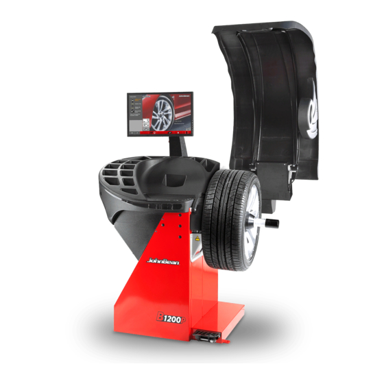
Page 14: Layout
Layout 4.0 Layout Refer to Figure 4-1. Functional description of the unit: 1. Display Refer to Chapter 4.1. 2. Wheel guard 3 External Detector - Sonar Refer to Chapter 4.8. 3a. Gauge arm Refer to Chapter 4.7. 4. Stub shaft 5. -
Page 15: Disposición
Disposition Disposición 4.0 Disposition Disposición Se reporter à la Figure 4-1. Hágase referencia a la Figura 4-1. Description fonctionnelle de la machine : Descripción funcional de la unidad: 1. Affichage 1. Pantalla táctil Consultar Capítulo 4.1. Se reporter au Chapitre 4.1. 2. - Page 16 Layout The screen Fig. 4-3 Screen with display fields. Display field. Information field. Commands field. The screen reads out inputs, helpful information, all measured data and possible error codes. Description of displayed fields Each field of the screen has a specific function. Display field Rim dimensions (editable).
- Page 17 Disposition Disposición Écran Pantalla Fig. 4-3 Écran avec zones d’affichage. Fig. 4-3 Zonas de visualización de la pantalla Zone d’affichage. Campo de visualización. Zone d’information. Campo de información. Zone Commandes. Campo de mandos. Sur l’écran sont affichés les paramètres, les textes En la pantalla se visualizan los datos introducidos, las d’aide, toutes les valeurs mesurées et les messages informaciones útiles para el operador, todos los valores...
- Page 18 Layout 4.1.1 Fundamental Commands Figure 4-4 Keypad Description of keys 1 Keys (example) – Activate certain functions for the execution and continuation of a specific operation of the cycle. The symbols on the keys show their functions, as specified below. 2 HOME key –...
- Page 19 Disposition Disposición 4.1.1 Commandes de base 4.1.1 Mandos Básicos Figure 4-4 Clavier Fig. 4-4 Teclado Description des touches 1 Touches (Exemple) Descripción de las teclas – Sélection des fonctions pour effectuer ou poursuivre 1 Tecla tipo (ejemplo) le pas de travail respectif. –...
- Page 20 Layout 4.1.2 Screen pages & Commands The Display field shows the main Operating Screen Pages. Each Screen Page contains basic commands, located at the bottom in the Commands Field. Further com- mands may be positioned in other parts of the screen, with specific Screen Pages and operating phases.
- Page 21 Disposition Disposición 4.1.2 Pages-écran & Commandes 4.1.2 Pantallas y Mandos La zone Affichage donne accès aux principales pages- El campo de visualización muestra las siguientes écran opérationnelles : Pantallas operativas: Chaque page contient des commandes de base, si- En cada Pantalla aparecen mandos de base ubicados tuées en bas dans le Champ Commandes.
- Page 22 Layout Fig. 4-6 RIM DATA ENTRY Rim data entry Screen. Open using the Manual Data Entry key (3, Fig. 4-5). Specific commands: 1 - HELP key - Selects HELP texts. 2 - HOME key - Returns you to the starting page (INTRO SCREEN).
- Page 23 Disposition Disposición Fig. 4-6 Fig. 4-6 RIM DATA ENTRY RIM DATA ENTRY Page-écran de saisie des données de la roue. Pantalla Introducción datos llanta. Pour accéder à la page, presser la touche Manual Acceder con la Tecla Manual Data Entry (3, Fig. 4-5). Data Entry (3, Fig.
- Page 24 Layout Fig. 4-7 BALANCING Balancing Screen. Open with the BALANCING key (5, Fig. 4-5). Commands: 1 - HELP key - For selecting HELP texts. 2 - HOME key - Returns you to the starting page (INTRO SCREEN). 3 - START key - Starts the measuring run. 4 - ESC key - To exit the option being executed or displayed.
- Page 25 Disposition Disposición Fig. 4-7 Fig. 4-7 BALANCING BALANCING Page-écran Équilibrage. Pantalla Equilibrado. Pour accéder à la page, presser la touche BALANCING Acceder con la Tecla BALANCING (5, Fig. 4-5). (5, Fig. 4-5). Los mandos son: Commandes : 1 - Tecla HELP - Para Seleccionar textos de AYUDA. 1 - Touche HELP - Sélection de textes d’AIDE.
- Page 26 Layout 14 - FULL VEHICLE PRINTOUT key - The operator may select one or more wheels and at the end of the procedure may print the relevant report. By selecting the key the menu of the FULL VEHICLE settings will be opened: PRINTOUT 14a - the key cancels all selections.
- Page 27 Disposition Disposición 14 - Touche FULL VEHICLE PRINTOUT - L’opérateur 14 - Tecla FULL VEHICLE PRINTOUT - El operador pourra sélectionner une ou plusieurs roues et à la fin podrá seleccionar una o más ruedas y al final del de la procédure il pourra imprimer le rapport relatif. procedimiento podrá...
- Page 28 Layout Fig. 4-8 SETTINGS Settings Screen. Open with the SETTINGS key (7, Fig. 4-5). Commands: 1 - HELP key - For selecting HELP texts. 2 - HOME key - Returns you to the starting page (INTRO SCREEN). 3 - USER CAL key - Starts the USER CALIBRATION ...
- Page 29 Disposition Disposición Fig. 4-8 Fig. 4-8 SETTINGS CONFIGURACIONES Page-écran Paramètres. Pantalla Configuraciones. Pour accéder à la page, presser la touche SETTINGS Acceder con la Tecla SETTINGS (7, Fig. 4-5). (7, Fig. 4-5). Los mandos son: Commandes : 1 - Tecla HELP - Para Seleccionar textos de AYUDA. 1 - Touche HELP - Sélection de textes d’AIDE.
- Page 30 Layout Fig. 4-10 OPTIMISATION/MINIMISATION Optimisation / Minimisation Screen. Open with the OPT/MIN key (5, Fig. 4-7) when on the Screen after a measuring run. Commands available during the entire cycle: 1 - HELP key - Selects HELP texts relating to the current function.
- Page 31 Disposition Disposición Fig. 4-10 Fig. 4-10 OPTIMISATION/MINIMISATION OPTIMIZACIÓN/MINIMIZACIÓN Page Optimisation de stabilité de marche/ Minimisation Pantalla Optimización/Minimización. Se accede con la Tecla OPT/MIN (5, Fig. 4-7) cuando des masses.. On accède à cette page par la touche OPT/MIN (5, está presente en pantalla tras el lanzamiento de Fig.
- Page 32 Layout 4.1.3 Settings After switching on the unit, a default weight mode is shown. The unit of measurement indicated at power up is inches, but the setting selected before switching off for grams / ounces remains. 4.1.3.1 Dimension Unit Toggle Default diameter and width unit setting: inches.
- Page 33 Disposition Disposición 4.1.3 Réglages 4.1.3 Configuraciones Après l’allumage de l’unité un type de roue est affiché Después de encender la unidad, se indica un modo par défaut. de Peso por defecto. L'unité de mesure par défaut de la machine est le Al encender la máquina la unidad de medida pouce, mais le réglage sélectionné...
- Page 34 Layout Pictographs and symbols Pictographs are viewed on the screen in all fields: in Information, Menu and Display fields. P1 Wheel type 1 - standard wheel - nominal size in inches or millimetres. P2 Wheel type 2 - motorcycle wheel P3 Alu 0 - normal - Standard weight positioning P4 Alu 1, Alu 1P P5 Alu 2, Alu 2P...
- Page 35 Disposition Disposición Symboles - Pictogrammes Símbolos y Pictogramas Sur l’écran, des pictogrammes sont affichés dans toutes En la pantalla se visualizan símbolos y pictogramas les zones d’affichage : dans les zones d’information, en todos los campos: en los campos de información, les zones de menu et dans la zone d’affichage.
- Page 36 Layout Pictographs • Pictogrammes • Piktogramme Symbols relating to OPTIMISATION / MINIMISATION operations P15 Start the measuring run. P16 Apply the Calibration weight. P17 Make a mark on left tyre side. P18 Make a mark on right tyre side. P19 Fit tyre on rim and inflate to the specified inflation pressure.
- Page 37 Disposition Disposición Symboles utilisés pour les opérations Símbolos correspondientes a las operaciones de d’OPTIMISATION/MINIMISATION OPTIMIZACIÓN/MINIMIZACIÓN P15 Le démarrage du lancement roue est demandé P15 Se requiere la ejecución del lanzamiento rueda. P16 L’application de la masse-étalon est demandée P16 Se requiere la aplicación del Peso de calibración. P17 Placer repère à...
- Page 38 Layout Help information Help information explains the current action and, in the case of an error code, provides hints for remedy. 4-12a Display help information Press the HELP key (Fig. 4-12a). The first screen with help information appears, e. g. to the screen WHEEL DATA ENTRY (Fig.
- Page 39 Disposition Disposición Textes d’aide Teclas de ayuda Les textes d’aide expliquent l’opération en cours et Los textos de ayuda explican la situación operativa y, donnent des consignes en cas de messages d’erreur si aparecen mensajes de error, facilitan indicaciones pour pouvoir trouver un remède. para la correspondiente eliminación.
- Page 40 Layout The screen relating to the fault appears, showing initial or basic information (Fig. 4-18). Press the stop key (Fig. 4-19). The second screen relating to the fault appears, showing more detailed and second level information (Fig. 4-20). Press the stop key (Fig. 4-19) to quit the HELP page. 4-18 4-19 Electromechanical stop...
- Page 41 Disposition Disposición La page relative à l'erreur signalée apparaît en Aparece la pantalla relativa al error indicado que fournissant une information initiale ou de premier proporciona información inicial o de primer nivel de la niveau à propos de l'anomalie (Fig. 4-18). anomalía (Fig.
- Page 42 Layout Stop brake Figure 4-22 Pedal of wheel stop brake Activate the pedal to brake the wheel holder chuck and make fixing nut clamping or unclamping easier. The wheel is also retained in the correct position to allow for an easier weight application. Warning: This stop brake is designed only to facilitate orientation of the wheel and must not be used for...
- Page 43 Disposition Disposición Blocage de l’arbre principal Freno de paro Figure 4-22 Pédale de blocage Figura 4-22 Pedal del freno de parada rueda L’arbre principal est bloqué quand la pédale est Pisando el pedal se frena el mandril porta-rueda actionnée. Cela permet de serrer ou de desserrer para facilitar el bloqueo o desbloqueo de la tuerca de l’écrou de serrage plus facilement fijación.
- Page 44 Layout Gauge arms Fig. 4-23 The arm is used to: - Measure the rim distance only in MANUAL mode. Arm, can be removed and folded upwards Feeler rod used to measure the rim (Distance) for all types of profiles. 4-23 Ultrasonic detector On the outer side of the rim the machine has an...
- Page 45 Disposition Disposición Piges de mesure Brazos de medición Fig. 4-23 Figura 4-23 Le bras permet de : El brazo permite: - Détecter la mesure de la distance de la jante dans - Medir la distancia de la llanta en modalidad le mode MANUEL uniquement.
-
Page 46: Operation
Operation 5.0 Operation Power up Be sure to be familiar with: - possible dangers, ( 1.0) - the unit ( 4.0). Please read through the operation manual and follow the instructions, especially when operating the wheel balancer for the first time. ... - Page 47 Utilisation Operaciónes 5.0 Utilisation 5.0 Funcionamiento Allumage Puesta en marcha Veuillez-vous familiariser avec : Familiarizarse con: - les dangers possibles, ( - posibles peligros, ( 1.0) 1.0) - la machine ( 4.0). - la unidad ( 4.0).
- Page 48 Operation 5.1.2 Status at switching on The electronic unit is factory-adjusted to the following operating modes, available after switch on: – AUTOMATIC Operating Mode – Wheel type 1 (car wheel with nominal dimensions in inches, width 6.5” and diameter 15.0”). –...
- Page 49 Utilisation Operaciónes 5.1.2 État à la mise en circuit 5.1.2 Estado en la puesta en marcha L’unité électronique est programmée par le fabricant La unidad electrónica está configurada por el fabricante para los siguientes modos operativas, disponibles de façon que les modes de fonctionnement suivants soient, disponibles juste après le démarrage : después de la puesta en marcha: –...
- Page 50 Operation Clamping/unclamping the wheel The electronics is so programmed that after turning on the machine, the clamping jaws remain in their current position and any movement must be activated intentionally by activating the pedal. 5.2.1 Clamping the wheel Note: Before clamping the wheel make sure the contact surfaces on wheel adaptor and rim are free from dirt and grease.
- Page 51 Utilisation Operaciónes Serrage / desserrage de roue Bloqueo/desbloqueo de la rueda La electrónica es programada para que los ganchos de La commande électrique est conçue telle qu’après sujeción permanezcan en su posición actual cuando la mise en circuit de l’interrupteur secteur les mors se pone en marcha la máquina;...
- Page 52 Operation 5.2.2 Unclamping the wheel Note: While the jaws unclamp, support the wheel WITH YOUR LEFT HAND so that it will not tilt when unclamped. Lift the pedal (Fig. 5-8). Remove the clamping sleeve from the chuck (Fig. 5-7b).
- Page 53 Utilisation Operaciónes 5.2.2 Desserrage de roue 5.2.2 Desbloqueo de la rueda Remarque : Pendant le desserrage des mors, retenir Nota: Durante la apertura de los ganchos de sujeción, la roue AVEC LA MAIN GAUCHE pour sujetar la rueda CON LA MANO IZQUIERDA qu’elle ne tombe pas lors du desserrage.
- Page 54 Operation Adapters for wheels without centre bore In order to work on rims without centre bore or to be fixed with the bores of stud-bolts or for example motorcycle wheels, the MZV-p device can be replaced with the clamping tool SCA, or with the ”Motorbike base Flange”...
- Page 55 Utilisation Operaciónes Replacement du moyen de Adaptadores para llantas sin serrage pour roues sans trou central agujero central Pour le centrage et le serrage des jantes sans trou Si en la máquina está previsto centrar las llantas central ou des roues de moto sur une équilibreuse sin agujero central a través de los agujeros de los «...
- Page 56 Operation Mounting the Power Clamp device No wheel should be mounted on the machine. WARNING: WHEN THE POWER CLAMP DEVICE MUST BE REFITTED ON THE MACHINE, SET THE OPERATING MODE C22 TO “DISABLED”; RELEASING THE POWER CLAMPING DEVICE IS DISABLED. Refer to Fig.
- Page 57 Utilisation Operaciónes Montage du moyen de serrage Power Clamp Montaje de la herramienta de fijación Power Clamp No debe haber ninguna rueda en la máquina. Il n’y a pas de roue sur la machine. MISE EN GARDE : SI LA MACHINE EST à NOUVEAU ADVERTENCIA: AL REMONTAR LA HERRAMIENTA DE FIJACIÓN POWER CLAMP, LA MODALIDAD MODIFIÉE POUR LE MOYEN DE SERRAGE...
- Page 58 Operation 5 . 4 W e i g h t a p p l i c a t i o n a n d Measurement methods 5.4.1 Weight application positions Normal Standard positioning of weights, spring weights on the rim edges (steel). Alu 1 Symmetrical application of stick-on weights on rim shoulders (aluminium).
- Page 59 Utilisation Operaciónes 5.4 Modes d’application des masses 5.4 Modos de aplicación de los et relevé des mesures pesos y detección de las medidas 5.4.1 Positions d’application des masses 5.4.1 Posiciones de aplicación de los pesos Normal Positionnement normal des masses, masses Normal Posicionamiento normal de los pesos, pesos à...
- Page 60 Operation 5 . 5 D a t a r e q u i r e d f o r w e i g h t application Normal Offset Distance (machine rim) Rim nominal diameter Rim nominal width Alu 1 Offset Distance (machine rim) Rim nominal diameter Rim nominal width Alu 2...
- Page 61 Utilisation Operaciónes 5.5 Données nécessaires pour 5.5 Datos necesarios para aplicar l’application des masses los pesos Normal Distance Offset (machine jante) Normal Distancia Offset (máquina llanta) Diamètre nominal de la jante Diámetro nominal llanta Largeur nominale de la jante Anchura nominal llanta Alu 1 Distance Offset (machine jante) Alu 1...
- Page 62 Operation 5.6 Data detection mode 5.6.1 Selections by the User For adequate rounded results and for a correct application of thresholds, select, before the measuring run: the operating mode (Fig. 5-15a). The Type of Vehicle before the measuring run. (Fig. 4-5) 5.6.2 Selecting the Type of Vehicle...
- Page 63 Utilisation Operaciónes 5.6 Mode de saisie des données 5.6 Modo de detección de los datos 5.6.1 Selección por el usuario 5.6.1 Sélections par l’utilisateur Pour des arrondissements adéquats des résultats Para redondeos adecuados de los resultados y para una correcta aplicación de los umbrales, es necesario et pour une application correcte des seuils, il est nécessaire de sélectionner avant le lancement de seleccionar antes del lanzamiento de medición:...
- Page 64 Operation W h e e l m e a s u r i n g r u n (AUTOMATIC) Note: Starting from the completely lifted position, lower the wheel guard, at medium speed without stops or jerks even to the side. WARNINGS: YOU MUST BE VERY CAREFUL WHEN LOWERING THE GUARD, AS THE MACHINE SIMULTANEOUSLY DETECTS THE DIAMETER,...
- Page 65 Utilisation Operaciónes L a n c e r l a r o u e ( M o d e Lanzamiento de la rueda AUTOMATIQUE) (AUTOMÁTICO) Remarque : Abaisser la protection roue en partant Nota: Bajar la protección rueda partiendo de la de la position de carter complètement soulevé, posición de cárter completamente elevado doucement et lentement, en évitant les à-coups,...
- Page 66 Operation 5.7.1 Advanced Spoke Detection This mode, to be enabled in case of need and only in “BALANCING” ( 5.9) and “BALANCE WITH RUN OUT” modes ( 5.8), allows exact identification of rim spokes position and size. It allows a more precise placement of weights behind the spokes.
- Page 67 Utilisation Operaciónes 5.7.1 Identification avancée rayons 5.7.1 Detección Avanzada Radios Ce mode, à activer si besoin est, exclusivement en Esta modalidad, que debe activarse cuando sea necesario, exclusivamente en las modalidades mode « ÉQUILIBRAGE » ( 5.9) et « ÉQUILIBRAGE ...
- Page 68 Operation AUTOMATIC Mode “BALANCE WITH RUN OUT” The following instructions describe the specific functions of the balancer in the “BALANCE WITH RUN OUT” mode. Icon shown in (Fig. 5-15) identifies active “BALANCE WITH RUN OUT” mode. The unit runs in automatic 5-15 mode.
- Page 69 Utilisation Operaciónes M o d e A U T O M A T I Q U E M o d o A U T O M Á T I C O « BALANCE WITH RUN OUT » "EQUILIBRADO CON RUN OUT" Les instructions suivantes décrivent les fonctionnalités Las siguientes instrucciones describen las spécifiques de l’équilibreuse dans le mode...
- Page 70 Operation As soon as run-out is carried out press button (1, Fig. 5-19) to access to the OPTIMA SCREEN. The optima screen may appear in the following cases: Run-out below threshold value and wheel without 5-19 defects (Fig. 5-20). Geometrical matching recommended, the foreseen improvement value is represented in green.
- Page 71 Utilisation Operaciónes Une fois le runout effectué, en appuyant sur le bouton Una vez realizado el runout, al presionar el pulsador (1, (1, Fig. 5-19), on accède à la page-écran OPTIMA Fig. 5-19), se accede a la pantalla OPTIMA SCREEN. SCREEN.
- Page 72 Operation It will be possible to access the graphs of the taken measurements from the OPTIMA SCREEN: A submenu will appear (Fig. 5-25): 1st - First Harmonic (Fig. 5-26): 2nd - Second Harmonic (Fig. 5-27): 3rd - Third Harmonic (Fig. 5-28): Run-out graph (Fig.
- Page 73 Utilisation Operaciónes Depuis la page-écran OPTIMA SCREEN, on pourra En la pantalla OPTIMA SCREEN se podrá acceder a accéder aux représentations graphiques des mesures los gráficos de las medidas efectuadas: effectuées : Se visualizará un submenú (Fig. 5-25): Un sous-menu sera affiché (Fig. 5-25) : Primer armónico (Fig.
- Page 74 Operation 5.8.1 Print Report After enabling the printing function of the screen page in the settings page, the print key is available (1). By pressing key (1) all the three available options will be shown: 2 - Customer Data Entry 3 - Single report prints 4 - Multiple report prints 5 - Current screen prints...
- Page 75 Utilisation Operaciónes 5.8.1 Impression du Rapport 5.8.1 Impresión del Informe Une fois la fonction d'impression de la page-écran Una vez habilitada la función de impresión de la des réglages habilitée, la touche d'impression est pantalla de la página configuraciones, está disponible disponible (1).
- Page 76 Operation 5.8.2 Geometric Matching Open the Matching procedure by pressing key 1 (Fig. 5-101). The Geometric Matching screen will open (Fig. 5-101). 5.8.2.1 Geometric Matching At the end of the wheel measuring run the balancer may prompt carrying out a geometric matching (icon at the top left of the screen), whose diagnosis can provide a substantial improvement to the wheel performance.
- Page 77 Utilisation Operaciónes 5.8.2 Centrage géométrique 5.8.2 Matching geométrico Il est possible d’accéder à la procédure de Centrage Se puede acceder al procedimiento de Matching con avec la touche 1 (Fig. 5-101). la tecla 1 (Fig. 5-101). La page-écran du Centrage géométrique apparaît Aparece la pantalla del Matching geométrico (Fig.
- Page 78 Operation AUTOMATIC Mode “BALANCING” The following instructions describe the specific functions of the wheel balancer in AUTOMATIC mode, “BALANCING”. Icon shown in (Fig. 5-31) indicates the “BALANCE” 5-31 mode is active. The unit operates in Automatic Mode. When the “BALANCING” mode is set via setup panel, the machine performs the automatic wheel data reading procedure and the user does not have to perform any setting before the measuring run (except...
- Page 79 Utilisation Operaciónes Mode AUTOMATIQUE Modo AUTOMÁTICO « ÉQUILIBRAGE » “EQUILIBRADO” Les instructions suivantes décrivent les Las instrucciones siguientes describen las fonctionnalités spécifiques de l’équilibreuse dans funcionalidades específicas de la equilibradora le mode AUTOMATIQUE, « ÉQUILIBRAGE ». en la modalidad AUTOMÁTICO, “EQUILIBRADO”. L’icône de la (Fig.
- Page 80 Operation 5.9.1 Rim Data Freeze The “Rim Data Freeze” function allows you to save the data detected on a first rim, of a group of identical wheels (usually four) to be balanced. This function enhances machine performance since it reduces the data acquisition time for the subsequent identical wheels after the first.
- Page 81 Utilisation Operaciónes 5.9.1 Bloquer les données de la roue 5.9.1 Bloqueo Datos Rueda Cette fonctionnalité, dénommée « Rim Data Freeze », Esta función, denominada “Rim Data Freeze”, permite permet de mémoriser les données mesurées sur une memorizar los datos medidos de la primera llanta de première jante pour un groupe de roues identiques un grupo de cuatro o más ruedas idénticas a equilibrar.
- Page 82 Operation The Rim data freeze condition set is also identified by the icon shown on the right of the monitor, with the following meaning: (Fig. 5-36) a) Yellow hatching for external and internal detectors, indicating that the Wheel Data Freeze function is not activated.
- Page 83 Utilisation Operaciónes La condition paramétrée de bloc données roue « Rim La condición programada Rim data freeze de bloqueo data freeze » est signalée aussi par une icône sur de los datos de la rueda, se identifica también por el l’écran à...
- Page 84 Operation 5.10 SPOKES OFF AUTOMATIC Mode “BALANCE NO SPOKES” The Spokes Off Automatic Mode has the same features 5.9), as the Automatic function already described ( except that it excludes automatic rim spoke detection. When it is established that no information about spokes is needed, in-depth spoke detection by the laser can be switched off.
- Page 85 Utilisation Operaciónes 5.10 M o d e A U T O M A T I Q U E 5.10 Modo AUTOMÁTICO RADIOS RAYONS EXCLUS « ÉQUILIBRAGE EXCLUIDOS "EQUILIBRADO SIN SANS RAYONS » RADIOS" Le mode Automatique Rayons exclus a les mêmes El Modo Automático Radios Excluidos tiene las mismas caractéristiques que la fonction Automatique características que la funcionalidad Automático ya...
- Page 86 Operation 5.11 Wheel measuring run (in Manual) This function is retrieved with the key (1, Fig. 5-41) available in the main Menu. – Check the wheel is clamped correctly ( 5.2). – Select the Type of Vehicle ( 5.6.2).
- Page 87 Utilisation Operaciónes 5.11 L a n c e m e n t d e r o u e ( e n 5.11 Lanzamiento de la rueda (en Manuel) el Manual) La fonction s’active avec le bouton (1, Fig. 5-41) A la función se accede con el botón (1, Fig. 5-41) disponible en el Menú...
- Page 88 Operation 5.12 Selections by the User Manual Mode with available data entry The Type of Vehicle must always be set and it must be done before extracting the arm to read the rim positions. 5.12.1 Distance manual entry X = Distance between cabinet edge and rim A = Value X (as measured) less 5 mm (= Value to be entered).
- Page 89 Utilisation Operaciónes 5.12 Sélections de la part de 5.12 S e l e c c i o n e s p o r p a r t e l'utilisateur du mode manuel del Usuario Modo Manual con avec introduction des données introducción datos disponibles disponibles La configuración del tipo de Vehículo siempre es...
- Page 90 Operation 5.13 Wheel Profiles function To balance more than one wheel of the same type and with the same nominal dimensions, simply set the data for the first wheel only. The data set remain until other new data are set or the machine is switched off. Note: This function in used in manual mode only.
- Page 91 Utilisation Operaciónes 5.13 Fonction Profils de roue 5.13 Función Perfiles de la Rueda Si plusieurs roues du même type et de valeurs Si se equilibran varias ruedas del mismo tipo y de nominales identiques sont équilibrées, les dimensions dimensiones nominales idénticas, los valores de la de la roue ne doivent être entrées que pour la première llanta solo se introducirán para la primera rueda.
- Page 92 Operation 5.13.1 Saving a Wheel Profile Up to 9 wheel profiles can be saved. Clamp the wheel you wish to save the profile of. Set and acquire all the wheel data, including the number of spokes if an Alu P is required. 5-48 In the RIM DATA ENTRY screen press the “PROFILES”...
- Page 93 Utilisation Operaciónes 5.13.1 Mémorisation d’un profil de roue 5.13.1 Memorización de un Perfil Rueda Il est possible de mémoriser un maximum de 9 profils Se pueden memorizar hasta 9 perfiles de rueda. de roue. Bloquear la rueda de la cual se desea memorizar Mettre en place la roue dont on souhaite mémoriser el perfil.
- Page 94 Operation 5.14 Weight application The following weight types and application methods are available: Clip-on weights. Always apply by hand (Figure 5-33). Stick-on weights. After wheel run, look at the rotation indicators for the left plane of the wheel (1, Fig. 4-13): •...
- Page 95 Utilisation Operaciónes 5.14 Pose des masses 5.14 Colocación del peso Les types de masses et méthodes de pose suivantes Los siguientes tipos de peso y de colocación están sont disponibles: disponibles: Masses agrafées. Pesos de grapa. Poser toujours manuellement (Figure 5-33). Aplicar siempre manualmente (Figura 5-33).
- Page 96 Operation 5.14.3 Alu 2P and Alu 3P weight application modes: 5.14.3.1 Using the Laser Pointer With the Laser Pointer mode active in Alu 2P and Alu 3P modes, the correction planes for stick-on weights are accurately indicated by the laser pointer directly on the rim (Fig.
- Page 97 Utilisation Operaciónes 5.14.3 Modes de pose des masses Alu 2P 5.14.3 Modos de aplicación del peso Alu et Alu 3P : 2P y Alu 3P: 5.14.3.1 Utiliser le Laser Pointer 5.14.3.1 Uso del Laser Pointer Avec le mode Laser Pointer actif, dans les modes Alu Con el modo Laser Pointer activo, en los modos Alu 2P et Alu 3P, les plans de correction pour les masses 2P y Alu 3P, el puntero láser indica con precisión...
- Page 98 Operation 5.14.4 Behind–the–spokes placement - SWM (Split Weight Mode) The behind-the-spokes placement mode (SWM) allows to split balance weights that, according to the machine, would have to be fitted in a visible position that probably the customer would not like. With the SWM Mode instead, two weights, equivalent to the first one, are placed behind the closest spokes (see example, Figure 5-57).
- Page 99 Utilisation Operaciónes 5.14.4 Positionnement des masses 5.14.4 Posicionamiento pesos detrás de derrière les rayons - SWM (Split Weight los radios - SWM (Split Weight Mode) Mode) El programa de equilibrado para el posicionamiento Le programme d'équilibrage pour le positionnement detrás de los radios (SWM) permite dividir los pesos de corrección que, de lo contrario, la máquina sugeriría des masses derrière les rayons (SWM) permet de aplicar en posición visible, incómoda para el cliente.
- Page 100 Operation Note: We suggest you keep the wheel in position with the brake pedal until the selection has been made. Use key (17,Fig. 5-60) to select the Item Hidden Weight behind spokes. The function is now selected and on the right of the 5-60 screen two balancing indicators are shown instead of one (Fig.
- Page 101 Utilisation Operaciónes Remarque : Il est conseillé de bloquer la roue Nota: Se aconseja mantener la rueda en posición en position avec le frein de blocage con el freno de pedal, hasta que se complete jusqu’à la fin de la sélection. la selección.
- Page 102 Operation 5.14.4.2 Hidden Weights placement Application of stick-on weights on the left side of the rim channel Clean the fitting position before attaching the stick- on weights. Fit the stick-on weight on the left side of the rim channel (Figure 5-63).
- Page 103 Utilisation Operaciónes 5.14.4.2 Fixation d’une masse cachée 5.14.4.2 Aplicación de pesos ocultos Placer la masse autocollante sur le côté Aplicación del peso adhesivo en el lado gauche du disque de jante izquierdo del canal de la llanta Avant de fixer les masses autocollantes, nettoyer ...
- Page 104 Operation 5.15 Check run It is good practice to perform a check run after applying the weights. • Start the run. Having finished the check run, if the wheel is balanced correctly, both the numerical indicators should indicate 0 and an OK should be displayed (Fig. 5-56). Warning If both unbalance value indicators show 0, but there is no OK reading, dynamic unbalances below the...
- Page 105 Utilisation Operaciónes 5.15 Lancement de contrôle 5.15 Lanzamiento de control Il est conseillé d’effectuer un lancement de contrôle Se aconseja efectuar una rotación de control después après avoir appliqué les masses. de aplicar los pesos. • Effectuer le lancement. • Efectuar el lanzamiento. Quand le lancement de vérification est terminé...
- Page 106 Operation 5.16 O p t i m i s a t i o n / W e i g h t Minimisation 5.16.1 General information The unbalance optimisation is used to minimise operation noise. During the optimisation the tyre is fitted on the rim in a specific position based on the result of the different unbalance measuring runs.
- Page 107 Utilisation Operaciónes 5.16 Optimisation / Minimisation 5.16 Optimización/ Minimización de des masses los pesos 5.16.1 Généralités 5.16.1 Información general L’optimisation du balourd sert à maximiser le silence La optimización del desequilibrio sirve para maximizar de marche. la suavidad de la marcha. Au cours du processus d’optimisation, la jante et le Durante la optimización el neumático se monta sobre pneu sont adaptés l’un à...
- Page 108 Operation 5.16.3 Start optimisation or weight minimisation Use key 6 (Fig. 4-10) or key 5 (Fig. 4-7) to access the optimisation or minimisation entry screen. Procedure: Clamp the wheel or bare rim. Enter correct rim dimensions, or check existing inputs for correctness.
- Page 109 Utilisation Operaciónes 5.16.3 Démarrer optimisation de stabilité 5.16.3 I n i c i o d e l a o p t i m i z a c i ó n o de marche ou minimisation des masses minimización de los pesos On pourra accéder à...
- Page 110 Operation Figure 5-68 OPTIMISATION “2” START is signalled on the screen. Perform the wheel measuring run. A compensation run is performed. The OPTIMISATION “3” screen appears (Fig. 5-69). 5-68 Figure 5-69 OPTIMISATION “3” Mount the tyre correctly on the rim (follow the centring line) and inflate to specified inflation pressure.
- Page 111 Utilisation Operaciónes Figure 5-68 OPTIMISATION « 2 » Figura 5-68 OPTIMIZACIÓN “2” START est alors affiché sur le moniteur. START aparecerá en la pantalla. Ejecutar el lanzamiento de la rueda. Effectuer un lancement de roue. Le lancement de compensation est effectué. Se realiza el lanzamiento de compensación.
- Page 112 Operation Figure 5-73 OPTIMISATION “6” (second measuring run with tyre) Rotate the wheel into marking position following the arrows. In this position mark the tyre, on the outer side of the wheel, precisely above the chuck. Confirm by pressing key 8. The OPTIMISATION “7”...
- Page 113 Utilisation Operaciónes Figure 5-73 OPTIMISATION « 6 » Figura 5-73 OPTIMIZACIÓN “6” (2ème lancement de mesure de l’ensemble pneu/ (2° lanzamiento de medición con neumático) jante) Girar la rueda hasta que esté en la posición de Tourner la roue en position de marquage (flèches marcado (flechas de dirección) ...
- Page 114 Operation The OPTIMISATION “9” screen appears (Fig. 5-77). Figure 5-77 OPTIMISATION “9” START is signalled on the screen Perform the wheel measuring run. A measuring run is performed. The OPTIMISATION “10” screen, outside, is displayed 5-77 (Fig. 5-78) or the OPTIMISATION “10” screen, inside, appears (Fig.
- Page 115 Utilisation Operaciónes La page-écran OPTIMISATION « 9 » est alors affichée Aparecerá la pantalla OPTIMIZACIÓN “9” (Fig. 5-77). (Fig. 5-77). Figura 5-77 OPTIMIZACIÓN “9” Figure 5-77 OPTIMISATION « 9 » Aparecerá START en la pantalla START est alors affiché sur le moniteur. ...
- Page 116 Operation Figure 5-78b OPTIMISATION “10”, outside Rotate the wheel into marking position following the arrows. In this position make a double mark on the tyre outer side exactly perpendicular to and above the chuck. Confirm by pressing key 8. ...
- Page 117 Utilisation Operaciónes Figure 5-78b OPTIMISATION « 10 », externe Figura 5-78b OPTIMIZACIÓN “10”, exterior Tourner la roue en position de marquage (flèches Girar la rueda hasta que esté en la posición de marcado (flechas de dirección) de direction). Dans cette position, faire un repère double sur En esta posición, hacer una señal de marcado ...
- Page 118 Operation Message E9 Message E9 means that at least one error has occurred during the optimisation cycle (System messages 7.1). Abort the optimisation program by pressing the STOP key and, if desired, start optimisation once again. 5-81 Figure 5-81 OPTIMISATION “12” (fourth measuring run with tyre) ...
- Page 119 Utilisation Operaciónes Affichage du code d’erreur E9 Al visualizarse el mensaje E9 Si E9 est affiché, c’est qu’il y a eu au moins une El mensaje E9 significa que ha habido por lo menos erreur relative à la séquence de programme lors de un error en el transcurso del programa durante la la procédure d’optimisation (Messages de système realización de la optimización (Mensajes del sistema...
- Page 120 Operation 5.16.3.2 WEIGHT MINIMISATION To directly perform compensation weights Minimisation, proceed as follows: In the BALANCING Menu press key 6 (Fig. 4-10) Optimisation-Minimisation. The OPTIMISATION-MINIMISATION screen is displayed (Fig. 4-10). Press key 4 (Fig. 4-10). The MINIMISATION “1” screen appears (Fig. 5-85). 4-10 Figure 5-85 MINIMISATION “1”...
- Page 121 Utilisation Operaciónes 5.16.3.2 MINIMISATION DES 5.16.3.2 MINIMIZACIÓN DE LOS MASSES PESOS Pour effectuer directement la minimisation des masses Para efectuar directamente la minimización de los de compensation, procéder comme suit : pesos de compensación: A partir du Menu BALANCING, presser la touche ...
- Page 122 Operation Figure 5-87b MINIMISATION “3” Rotate the wheel into marking position following the arrows. In this position mark the tyre, on the outer side of the wheel, precisely above the chuck. Confirm by pressing key 8. The MINIMISATION “4” screen appears (Fig. 5-88). 5-87b Figure 5-88 MINIMISATION “4”...
- Page 123 Utilisation Operaciónes Figure 5-87b MINIMISATION « 3 » Figura 5-87b MINIMIZACIÓN “3” Tourner la roue en position de marquage (flèches Girar la rueda hasta que esté en la posición de marcado (flechas de dirección) de direction). Dans cette position, marquer le pneu, sur sa ...
- Page 124 Operation Figure 5-92 MINIMISATION “7”, outside Rotate the wheel into marking position following the arrows In this position make a double mark on the tyre outer side exactly perpendicular to and above the chuck. Confirm by pressing key 8. The MINIMISATION “8”...
- Page 125 Utilisation Operaciónes Figure 5-92 MINIMISATION « 7 », externe Figura 5-92 MINIMIZACIÓN “7”, exterior Tourner la roue en position de marquage (flèches Girar la rueda hasta que esté en la posición de marcado (flechas de dirección) de direction). ...
- Page 126 Operation Message E9 Message E9 means that at least one error has occurred during the optimisation cycle (System messages 7.1). Abort the optimisation program by pressing the STOP key and, if desired, start optimisation once again. Figure 5-95 MINIMISATION “9” 5-95 ...
- Page 127 Utilisation Operaciónes Affichage du code d’erreur E9 Al visualizarse el mensaje E9 Si E9 est affiché, c’est qu’il y a eu au moins une El mensaje E9 significa que ha habido por lo menos erreur relative à la séquence de programme lors de un error en el transcurso del programa durante la la procédure d’optimisation (Messages de système realización de la optimización (Mensajes del sistema...
-
Page 128: Maintenance
Maintenance Maintenance This unit is designed to operate for a long time. 5.1.3) If the operator shuts down the unit correctly ( at the end of each shift, no further maintenance is required. This unit must not be opened by the operator, except in accordance with explicit instructions. - Page 129 Entretien Mantenimiento Entretien Mantenimiento Esta unidad está diseñada para durar mucho tiempo. Cette machine est conçue pour vous donner un service de longue durée. Si el operador apaga la unidad correctamente ( Si l’opérateur éteint correctement la machine ( 5.1.3) al final de su turno, no es necesario hacer un 5.1.3) après son utilisation, aucune maintenance mantenimiento adicional.
- Page 130 Maintenance User Calibration If several measuring runs are necessary to balance a wheel because balance weight size and position have to be adjusted repeatedly, this is often due to insufficient measurement accuracy. If this is the case the operator can electronically calibrate the rotating masses on the machine;...
- Page 131 Entretien Mantenimiento Étalonnage par l’opérateur Calibración del Usuario S’il faut effectuer plusieurs lancements de mesures Si se precisan varios lanzamientos de medición para afin d’équilibrer une roue, en particulier pour corriger equilibrar una rueda porque hace falta corregir varias la grandeur et la position de la masse d’équilibrage, veces la magnitud y la posición de los contrapesos, la ce phénomène sera, dans la plupart des cas, dû...
- Page 132 Maintenance Monitor Calibration Follow the figures 6.7 (1, 2, 3). Keeping the STOP key pressed for more than 3 seconds in the “Home” screen the calibration process starts. The process is performed in 3 stages. The operator must touch in three different times the white dot with the cross indicator shown on the screen.
- Page 133 Entretien Mantenimiento Calibrage du moniteur Calibración del monitor Suivre les Figures 6.7 (1, 2, 3). Seguir las Figuras 6.7 (1, 2, 3). Lorsque la touche STOP de la page-écran “Home” est Manteniendo presionada durante más de 3 segundos enfoncée pendant plus de 3 secondes le processus la tecla STOP en la pantalla “Home”, se pone en de calibrage est lancé.
- Page 134 Maintenance WARNING: BEFORE ATTEMPTING ANY MAINTENANCE OR REPAIRS, DISCONNECT THE BALANCER FROM THE POWER SUPPLY. Changing the mains fuse Refer to Figure 6-8. • Switch off the unit. • Unplug the power cable from the power outlet. • Disconnect the power cable from the machine socket (1).
- Page 135 Entretien Mantenimiento ATTENTION : AVANT TOUTE OPERATION ATENCIÓN: ANTES DE CUALQUIER OPERACIÓN D ’ E N T R E T I E N O U D E R E PA R AT I O N , DE MANTENIMIENTO O REPARACIÓN, D E B R A N C H E R L’...
-
Page 136: Trouble Shotting
Trouble shooting 7.0 Troubleshooting If a problem arises with the wheel balancer, proceed in the following order to solve the problem: 1. Rethink the last steps taken. Did you work according to the manual? Did the unit work as described and expected? 2. - Page 137 Dépannage Resolución de problemas Dépannage 7.0 Resolución de problemas En cas de problème avec l’équilibreuse, procéder Si ocurre algún problema en la equilibradora, es comme suit pour résoudre le problème : preciso proceder en el siguiente orden para resolverlo: 1. Remémorer les dernières actions effectuées. Le 1.
- Page 138 Trouble shooting Balancing results are unreliable. 1. The balancer may not be installed properly. • Make sure the unit rests on its three feet only. • Make sure the floor is not transmitting shocks, for example from trucks passing close to the unit. 2.
- Page 139 Dépannage Resolución de problemas Les résultats d’équilibrage ne sont pas consistants. Los resultados de equilibrado no son fiables. 1. L’équilibreuse n’est pas installée correctement. 1. Quizás la equilibradora no esté instalada • Vérifier que la machine repose sur ses trois pieds correctamente.
- Page 140 Trouble shooting System messages The wheel balancer can send messages to the operator relevant to errors (E codes) (e.g.E2 - Fig. 7-1), warnings (H-codes) (e.g.H 33 - Fig. 7-2) or Hardware problems (X-codes). The codes will be described in the following chapters. Whenever a code appears: • Make a note of it.
- Page 141 Dépannage Resolución de problemas Messages de système Mensajes del sistema La equilibradora puede mostrar al operador mensajes L’équilibreuse est en mesure d’envoyer à l’opérateur relativos a errores (códigos E) (ej.E 2 - Fig. 7-1), des messages relatifs aux erreurs (codes E) (ex.E 2 advertencias (códigos H) (ej.H 33 - Fig.
- Page 142 Trouble shooting Valve position was not set (message appears only with optimisation or minimisation programs). Position valve exactly perpendicular to and above chuck and press the OP key. The power clamp device is not clamped. The measuring run has been started with the device not clamped correctly.
- Page 143 Dépannage Resolución de problemas No se introdujo la posición de la válvula (este mensaje La position de la valve n’a pas été entrée (code se visualiza solo con el programa de optimización/ d’erreur seulement en programmes d’optimisation/ minimización de pesos). minimisation).
- Page 144 Trouble shooting The rotating speed of the chuck exceeds the safety limit. A key is jammed or the pedal switch is closed. Find and release jammed key. Press STOP or ESC key to check the switch. If the error cannot be remedied, the pedal function is switched off by pressing the STOP key or the ESC key.
- Page 145 Dépannage Resolución de problemas La vitesse de l’arbre principal dépasse la plage de El número de revoluciones del mandril supera el régimen de seguridad. sécurité. Une touche s’est coincée ou le commutateur de Una tecla está atascada o el interruptor del pedal pédale est fermé.
- Page 146 Trouble shooting E500 Laser Pointer failure • Contact technical service team. E501 Laser Pointer failure • Contact technical service team. E502 Laser Pointer failure • Contact technical service team. E503 Laser Pointer failure • Contact technical service team. E504 Laser Pointer failure • Contact technical service team.
- Page 147 Dépannage Resolución de problemas E500 E500 Dysfonctionnement pointeur laser Malfuncionamiento del Puntero Láser • Contactar con el Servicio Técnico. • Faire appel au service après-vente. E501 E501 Malfuncionamiento del Puntero Láser Dysfonctionnement pointeur laser • Contactar con el Servicio Técnico. • Faire appel au service après-vente.
- Page 148 Trouble shooting The gauge was moved too slowly. Return the gauge to the starting position and repeat the operation, bringing the gauge towards the weight application point again. The SONAR does not work. Recalibration was not set up. As a result, it cannot be performed by the operator.
- Page 149 Dépannage Resolución de problemas La pige de mesure a été actionnée trop lentement. El brazo de medición se movió demasiado lentamente. Remettre la pige en position de repos et l’approcher de Volver a colocar el brazo de medición en la posición inicial nouveau au point de palpage du positionnement des y hacerlo avanzar de nuevo en la posición de aplicación masses d’équilibrage.
- Page 150 Trouble shooting 7.1.3 Fatal error messages The display shows a code consisting of six digits and/or letters. When message codes are starting with 300xxx the error occurred during the internal monitoring phase, if they are starting with C10xxx the error occurred during the self–test after the machine was switched on.
- Page 151 Dépannage Resolución de problemas 7.1.3 Message d’erreur fatale 7.1.3 Mensajes de Error fatal L’afficheur affiche un code à 6 chiffres et/ou lettres. S’il El indicador muestra un código de 6 cifras y/o letras. y a des messages commençant par 300xxx, l’erreur Los mensajes de código 300xxx señalan los errores se présentait pendant le contrôle de fonctionnement que se han presentado durante la supervisión interna,...
- Page 152 Trouble shooting Storage When the unit will be stored for a several weeks or longer, prepare the unit correctly: • Shut down the unit properly, 5.1.3. • Remove the stub shaft from the balancer. • Apply a thin layer of non-corrosive oil on all threads and cones.
- Page 153 Dépannage Resolución de problemas Stockage Almacenamiento Lorsque la machine est entreposée pendant plusieurs Cuando se vaya a guardar la unidad durante varias semaines ou plus, préparer correctement la machine : semanas, es preciso prepararla adecuadamente: • Éteindre correctement la machine 5.1.3.
- Page 154 Setting Parameters Settings Normal operation usually does not require any modification of the factory–adjusted modes of operation or their factory–adjusted statuses. Variations, however, can be made by selecting certain specific items in the SETTINGS screen. In addition to the changes made to the functioning modes, from this menu various counters can be displayed showing the operations carried out over time by the balancer.
- Page 155 Réglage des paramètres Configuración Parámetros Réglages Configuraciones Pour le fonctionnement normal, il n’est généralement pas Para el funcionamiento normal no suele ser necesario nécessaire de changer les modes de fonctionnement cambiar las modalidades operativas y sus estados programados por el fabricante. ou leur état programmé...
- Page 156 Setting Parameters Saving Changed Parameters Changes to operating modes can be saved permanently using the “Saving operating modes in the permanent memory” function so they are retained every time the machine is started up. Operating modes that are changed but not saved are reset to the pre-change value after the machine has been switched off.
- Page 157 Réglage des paramètres Configuración Parámetros Mémoriser les paramètres modifiés Memorizar los Parámetros Modificados Las modificaciones de los modos operativos pueden Les modifications des modes de fonctionnement peuvent également être enregistrées dans la mémoire ser memorizadas de modo permanente mediante permanente avec la fonction « Sauvegarde des modes la función “Registro de los modos operativos en la de fonctionnement dans mémoire permanente »...
- Page 158 Setting Parameters D) Selection of the unit of measurement for run-out, in mm or inches. Default value: mm. E) Limit (threshold) for wheel peak-to-peak radial Run- out. Default value: 1.5 mm. F) Scanning for wheel information detection is always performed during the first run. Should it be necessary to carry out more than one run for the same wheel, this function allows disabling the laser scanners during any further runs after the first, so as to...
- Page 159 Réglage des paramètres Configuración Parámetros D) Choix de l’unité de mesure du voile en mm ou inch. D) Selección de la unidad de medida del runout en Valeur prédéfinie : mm. mm o inch. Valor predeterminado: mm. E) Limite (seuil) pour le Voile radial crête-crête de la roue.
- Page 160 Setting Parameters 7.4.2 List of operating modes The possible changes of modes are described in the following. Setting modes of operation as recommended See § 5. Switching on the machine. = No action Active = Recalls the values pre-set by the factory. The selected operating mode can be acquired in the permanent memory.
- Page 161 Réglage des paramètres Configuración Parámetros 7.4.2 Liste des modes de 7.4.2 Lista de los Modos Operativos fonctionnement Se presentan a continuación los posibles Modos modificables. Ci-dessous sont listés les changements possibles des modes de fonctionnement. Configuración valores por defecto Ensemble des modes opératoires possibles Véase capítulo 5.
- Page 162 Setting Parameters Resolution of the unbalance amount readings Resolution of the unbalance amount readings Selecting the resolution of unbalance readings in Selecting the resolution of unbalance readings 1 or 5 g, or 0.05 or 0.25 oz increments. in 0.05 / 0.25 oz or 1 / 5 g, increments. Normal* 5 g ( 0 .
- Page 163 Réglage des paramètres Configuración Parámetros Résolution affichage valeur du balourd Seuil du dèséquilibre affiché Resolución de la lectura del valor de Resolución de la lectura cantidad de desequilibrio desequilibrio Choix des échelons pour l’affichage du balourd de Choix des échelonspour l’affichage du balourd 1 ou 5 g, ou 0,05 ou 0,25 oz Selección de la resolución indicador valor Selección del nivel de incremento de la cantidad...
- Page 164 Setting Parameters Start the measuring run by closing the wheel guard Off = Start via START key On* = Start via wheel guard The selected operating mode can be acquired in the permanent memory. Automatic braking when the wheel guard is raised Off = No braking...
- Page 165 Réglage des paramètres Configuración Parámetros Démarrage lancement de mesure par fermeture Inicio del lanzamiento de medición al bajar la du carter de roue protección de la rueda Off = Lancé par la touche START Desconectado = Iniciar pulsando la tecla START On* = Lancé...
- Page 166 Setting Parameters Counters Every measuring run actually completed is stored. Maximum count is 999,999 runs. Once this number is reached, the counter is reset to zero. The information is primarily useful for statistical purposes, e.g. to obtain evidence of load intervals of parts when defective, or of monthly (yearly) use of the machine, etc.
- Page 167 Réglage des paramètres Configuración Parámetros Compteurs Contadores Chaque lancement de mesure terminé sera mis en Se almacenan todos los lanzamientos de medición mémoire. terminados. Le compte maxi est de 999.999 lancements de mesure. Se pueden contar como máximo 999.999 lanzamientos Une fois ce nombre atteint, le compteur est remis à...
- Page 168 Setting Parameters Customer Data Entry The “Customer Data Entry” function (Figure 7-9) is used to fill in a customer/vehicle sheet to customise the print reports prepared by the balancer after the various operations. The data can be entered either before or after the measuring run.
- Page 169 Réglage des paramètres Configuración Parámetros Saisie Données Client Introducción Datos Cliente « Customer Data Entry » “Customer Data Entry” Avec la fonctionnalité Saisie Données Client « Con la función Introducción Datos Cliente “Customer Customer Data Entry » (Figure 7-9), le système Data Entry”...
- Page 170 Setting Parameters Weights Use Monitoring The function requires a USB support to save the data and display the time statistics. This support must be initialised with a service code (C125) (a technician’s intervention is necessary the first time). Once initialised, the USB support must be permanently left inserted in the wheel balancer.
- Page 171 Réglage des paramètres Configuración Parámetros Surveillance de l’utilisation Monitorización de la des poids utilización de pesos La función requiere un soporte USB para poder memorizar La fonction nécessite un support USB pour pouvoir los datos y ver las estadísticas a lo largo del tiempo. enregistrer les données et afficher les statistiques Este soporte se inicializa adecuadamente con dans le temps.
-
Page 172: Disposing Of The Unit
Disposal / Appendices Disposal When you decide to get rid of your unit, contact your reseller for a quote or for the regulations on disposal which apply to the unit. 8.1 INSTRUCTIONS FOR DISPOSAL IN EEC COUNTRIES For waste electrical and electronic equipment A t t h e t i m e o f d i s p o s a l , a t t h e e n d o f the lifetime of this equipment, you must:... - Page 173 Vente / Annexes Eliminación / Anexo Vente Desguace Au moment de l'élimination et de la mise au rebut de Cuando decida deshacerse de la unidad, póngase l'unité, contacter le revendeur pour une offre ou pour en contacto con el revendedor para que le haga una prendre connaissance des dispositions en matière oferta o para conocer las normas para el desguace d'élimination et mise au rebut prévues pour l'unité.
- Page 174 Blank Page...
-
Page 175: Appendix: Installation Instructions
Appendix: Installation Instructions This appendix describes the installation requirements, installation procedures and checks. Appendice : Instructions d’installation Cet appendice contient les conditions requises, les procédures et les vérifications nécessaires pour l’installation. Anexo: Instrucciones para la instalación En este anexo se describen los requisitos, procedimientos de instalación y los controles. - Page 176 Installation i. Installation requirements Space requirements The drawing show the minimum safety requirements: Fig. i.1 The drawing has two sets of dimensions: • from the wall to the cabinet surfaces • in the center of the fixing holes of the cabinet. Floor requirements The floor should be: - horizontal;...
- Page 177 Installation Instalación i. Conditions d’installation i. Requisitos de Instalación Conditions d’espace Requisitos de espacio El dibujo muestra los requisitos mínimos necesarios Le dessin montre les conditions minimum nécessaires à la sécurité: desde el punto de vista de la seguridad: Fig. i.1 Fig.
- Page 178 Installation ii Transport, unpacking and contents Carriage instructions The wheel balancer is supplied on a pallet. • Use a pallet truck (Figure ii-1) to bring the unit to its working area. Unpacking WARNING: PREVENT THE STRAPS FROM SPRINGING LOOSE AFTER BEING CUT. • Cut the straps.
- Page 179 Installation Instalación ii Manipulation, déballage et contenu ii Transporte, embalaje y contenidos Transport Transporte L’unité est fournie sur une palette. La unidad se suministra en palet. • Utilisez un transpalette (Figure ii-1) pour l’apporter • Usar una carretilla de palets(Figura ii-1) para trasladar la unidad a su zona de trabajo.
- Page 180 Installation iii Installation procedures Unit: Refer to the drawing in i section for correct wheel bal- ancer positioning. If the wheel balancer needs secur- ing, we recommend fixing elements with a diameter of 8 mm, quality 8.8 or higher. Supports for Accessories: • Unpack the 4 threaded accessory support studs and the support plates.
- Page 181 Installation Instalación iii Procédures d’installation iii Procedimiento de Instalación Unité : Unidad: Voir le graphique correct, section i, pour positionner Consultar el gráfico, sección i, para colocar la equili- correctement l’équilibreuse. Si l’équilibreuse doit être bradora correctamente. Si hay que sujetar la equilib- fixée, nous conseillons des éléments de fixation avec radora, se recomienda un tipo de fijación con pernos un arbre d’écrou de 8 mm, qualité...
- Page 182 309 Exchange Ave. Conway, AR 72032 Ph: 501-450-1500 Fax: 501-450-2085 Notice: The information contained in this document is subject to change without notice. Snap-on Equipment makes no warranty with regard to present documentation. Snap-on Equipment shall not be liable for errors contained herein or for incidental consequential damages in connection with furnishings, performance, or use of this material.
Need help?
Do you have a question about the B 1200P and is the answer not in the manual?
Questions and answers
Error message 33