
Related Manuals for John Bean VPI SYSTEM II


Summary of Contents for John Bean VPI SYSTEM II
- Page 1 FOR: PASSENGER CAR & LIGHT TRUCK WHEELS OPERATION INSTRUCTIONS Form ZEEWB503D Rev 12/14/20010...
- Page 3 It is assumed that, prior to using the Model VPI System II Wheel Balancer, the operator has a thorough understanding of the wheels and tires being serviced. In addition, it is...
-
Page 4: General Safety Instructions
IMPORTANT SAFETY INSTRUCTIONS When using this equipment, basic safety precautions should always be followed, including the following: Read all instructions. Do not operate equipment with a damaged power cord or if the equipment has been damaged - until it has been examined by a qualified authorized service technician. If an extension cord is used, a cord with a current rating equal to or more than that of the machine should be used. -
Page 5: Table Of Contents
John Bean VPI System II Operators Manual TABLE OF CONTENTS General Safety Instructions Page 2 Introduction Page 4 Safety Notice Page 4 Balancer Application Page 4 Specifications Page 5 Balancer Features Page 5 Standard Accessories Page 6 Optional Accessories Page 6... -
Page 6: Introduction
Read carefully all warnings and instructions of this manual since they provide important information concerning safety and maintenance. 1.2 BALANCER APPLICATION The John Bean wheel balancer model VPI System II is intended to be used as a device to balance car, and light truck wheels within the following range: Maximum wheel diameter : 44”... -
Page 7: Specifications
John Bean VPI System II Operators Manual 1.3 VPI System II SPECIFICATIONS 1.4 FEATURES ACCURACY Computerized digital wheel balancer for car, light truck • Weight placement accuracy is ± .7° wheels. • Weight imbalance accuracy to 2 grams. • Self test check with every power up cycle. -
Page 8: Standard Accessories
1.5 STANDARD ACCESSORIES 1.6 OPTIONAL ACCESSORIES EAC0058D15A Soft Protector ring EAC0058D07A Cup - Pressure EAC0058D08A Disk - Pressure EAA0263G66A Quick Nut EAM0021D90A Standard 40mm Stub Shaft EAM0005D40A Weight - Calibration EAC0060G02A Flange - Cover, Hook 4 PC Cone Kit, p/n EAK0221J60A, contains: EAM0006G01A Pin - Accessory EAM0003J08A... -
Page 9: Dimensions Of The Machine
John Bean VPI System II Operators Manual PRE-INSTALLATION CONSIDERATIONS 1.7 DIMENSIONS OF THE MACHINE Figure 5 - Recommended Work Area 1.9 INSTALLATION INSTRUCTIONS CAUTION! CAREFULLY REMOVE THE BALANCER FROM THE PALLET. Remove the hardware that secures the machine to Figure 4 - Actual Footprint Dimensions. -
Page 10: Wheel Guard Installation
B. Install the accessory pins (Figure 7). Tighten firmly. Figure 8 2.2 ELECTRIC INSTALLATION ANY ELECTRICAL WIRING MUST BE PER- FORMED BY LICENSED PERSONNEL. ALL SERVICE MUST BE PERFORMED BY AN AUTHORIZED SERVICE TECHNICIAN. Figure 7 Check on the plate of the machine that the electrical specifications of the power source are the same as the C. -
Page 11: Terminology
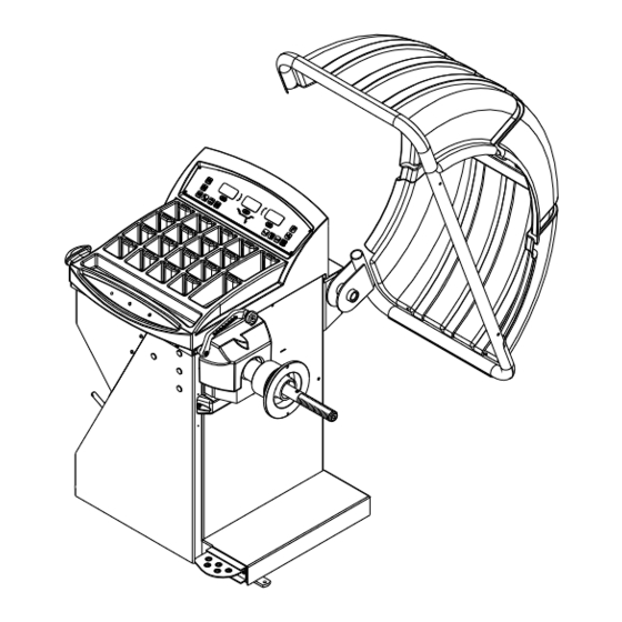
John Bean VPI System II Operators Manual 3.0 TERMINOLOGY Figure 9 Before using the wheel balancer it is suggested that you become familiar with the terminology and features of the machine’s components. Refer to Figures 9 and 10 for identification and location. -
Page 12: Balancer Operation
1 and 2 of this manual. There are many types of wheels and John Bean sup- plies adaptors of good quality and durability for the large majority. However if you meet special wheels which may... -
Page 13: Mounting Of Light Truck Wheels
John Bean VPI System II Operators Manual 4.3 MODE SELECTION Figure 12 The majority of balancing takes place in the default 2- plane dynamic mode which is displayed as "2 PL" (location 1). Hammer-on clip weights will be placed on both inside and outside of the rim edge. -
Page 14: Selecting Operator Preferences
C. ALUMINUM MODES. Balancing using a combina- 4.4 SELECTING OPERATOR PREFERENCES tion of hammer-on and adhesive weights as shown in Figures 17 thru 21. 4.4.1 FINE BALANCING MODE This balancer measures with the maximum precision available all the time, 1g / 0.05 oz, however values below 5g / 0.25 oz are shown as zero while in the normal oper- ating mode. - Page 15 John Bean VPI System II Operators Manual NOTE: It must be very clear that the feature works assuming that some residual imbalance can be left on the wheel. The tire shop will save weight, but wheels will be balanced with a lower degree of accuracy.
-
Page 16: Entering Rim Parameters
4.5 ENTER RIM PARAMETERS 4.5.3 Rim Diameter Entry - Select the Manual Diameter button (#11 page 9). Read the rim diam- eter marked on the sidewall of the tire (Figure 24). 4.5.1 Rim Distance (offset) - Move the rim offset Press the Diameter Button and enter the measured arm to the edge of the rim, touch the pointer to the rim diameter by rotating the shaft until the desired... -
Page 17: Verifying Results
John Bean VPI System II Operators Manual NOTE: Do not use the foot operated shaft lock as a brake, it is intended to be used only to prevent shaft rotation while placing corrective weights. B. Read the imbalance value on the outer display. Val-... -
Page 18: Matching Program
5.0 TIRE MATCHING PROGRAM - F90 Tire matching assists the user in determining the best possible mating of the tire and rim. The mating of tire and wheel normally allows the least amount of additional weight required for balancing and total runout. The matching program is helpful when: •... - Page 19 John Bean VPI System II Operators Manual NOTE: THE "F" BUTTON CAN BE PRESSED AS OF- TEN AS NECESSARY, WITH EVERY PRESS THE MACHINE UPDATES THE MEMORY OF THE VALVE POSITION. 5. The machine displays "ACH SPN 2 ". Lower the wheel guard to spin the wheel, when the shaft reaches the balancing speed, machine displays "--- ACH ---"...
-
Page 20: Optimization Program
If the Cancel/Stop Button is pressed now, machine dis- If the Cancel/Stop Button is pressed within one and half plays "Qit Qit Qit" for one and half second to remind second, machine will display "Qit Qit Qit" for one and operator whether he/she wants to quit optimization or half seconds indicating cancelation of optimization re- not. -
Page 21: Alu-S Program
John Bean VPI System II Operators Manual 7.0 ALU-S 2-PLANE MODE This is a mode similar to ALU mode 2 and 3. The differ- ence is that the distance and width parameters are ac- curately defined for a more exacting weight placement, therefore improving the likelihood of a single spin bal- ance. -
Page 22: Spoke Mode
8.0 SPOKE BALANCING MODE A standard dynamic balance places compensation weight in two planes, inner and outer, at the top dead center 180 degrees of each plane of calculated imbalance. Sometimes the outside weight placement may be unsightly on a cus- tom wheel. -
Page 23: Split Weight Mode
John Bean VPI System II Operators Manual 9.0 SPLIT WEIGHTS - F92 The “Split Weight” function is used to split one large weight to two smaller weights with 60% of original weight and 33.6° away each direction from the original position. -
Page 24: User Shaft Calibration
10.0 USER CALIBRATION The VPI System II Balancer features a calibration verifi- cation program which requires only a few minutes to complete. Perform this procedure to verify calibration when the balancer has been moved, disturbed, or when- ever accuracy is questioned. If the calibration process fails a service technian shouild be dispatched to perform a complete calibration. -
Page 25: Distance/Diameter Gauge Calibration
John Bean VPI System II Operators Manual 11.0 SAPE GAUGE CALIBRATION - F80 To calibrate the SAPE gauge. 1. Make sure the SAPE arm is in the home position as shown in Figure 41. NOTE: WEIGHT TRAY MUST BE INSTALLED TO IN- SURE PROPER HOME REFERENCE POSITION. -
Page 26: Explanation Of "F" Codes
12.0 EXPLANATION OF PROGRAM CODES 13.0 MAINTENANCE Various functions and features can be programmed to enhance operation. These programs are referred to as “F Codes”. Activate the “F Code” programs by press- BEFORE ANY MAINTENANCE OR RE- ing and holding the F Button while turning the shaft PAIRS ARE ATTEMPTED THE MACHINE until the desired number is displayed on the right dis- MUST BE DISCONNECTED FROM THE... - Page 27 NOTES:...
- Page 28 Notice: The information contained in this document is subject to change without notice. John Bean makes no warranty with regard to this material. John Bean shall not be liable for errors contained herein or for incidental consequential damages in connection with furnishings, performance, or use of this material.
Need help?
Do you have a question about the VPI SYSTEM II and is the answer not in the manual?
Questions and answers