Table of Contents
Advertisement
Advertisement
Table of Contents

Related Manuals for John Bean VPI System IV


Summary of Contents for John Bean VPI System IV
- Page 1 OPERATION INSTRUCTIONS Form ZEEWB516A...
-
Page 2: Table Of Contents
Table of Contents. 1 Safety............................5 1.1 Typography.......................... 5 2 Specifications......................... 6 2.1 Conditions........................... 6 3 Introduction..........................8 3.1 Accessories........................10 4 Layout..........................12 4.1 The Screen ......................... 12 4.1.1 Pictographs - Symbols ....................13 4.1.2 Menu Fields ........................ - Page 3 5.4.4 Static Unbalance ......................73 5.5. Special Functions ......................80 5.5.1 Behind-the-spokes Placement ..................80 5.5.2 Correction Of Measured Unbalance ................81 5.5.3 Changing Modes Of Operation..................83 5.5.3.1 List Of Modes Of Operation..................84 5.5.3.2 Counters ........................86 5.5.3.3 Input Of Promotional Text ................... 86 5.5.4 Optimization/ Weight Minimization .................
-
Page 5: Safety
Safety 1 Safety. All Safety Precautions relevant to the unit are described in the Safety Booklet, refer to Figure 1-1. The Safety Precautions should be fully understood by every operator. We suggest to store (a copy) of the Safety Booklet near the unit, in sight of the operator. The Operator’s Manual will contain specific warnings and cautions when possible dangerous situations may be encountered during the described procedures. -
Page 6: Specifications
Specifications Specifications. Power: Power Supply 230 V~, 50/60 Hz, 1 ph Motor rating 0.12 Power consumption Mains fuses 2x IEC 127 T5A Protection class IP54 Measurements: Measuring time >3 Measuring speed <200 Offset 0-400 Increments: inch (<10”) 0.5 (.25) ” mm (PAX) Wheel dimensions: Max. -
Page 7: Introduction
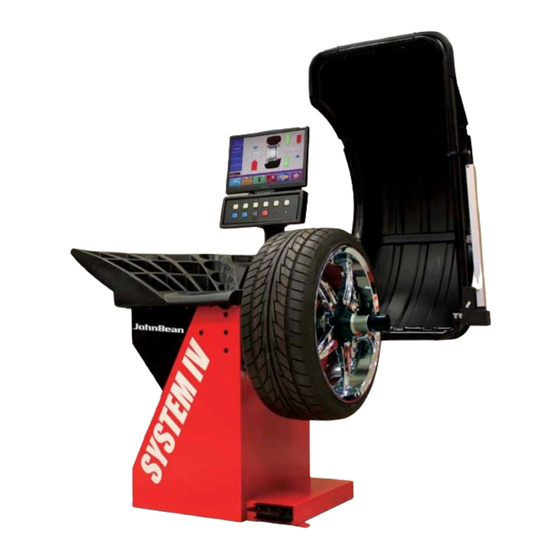
Introduction Introduction. This wheel balancer combines advanced, high- performance technology, robustness and reliability with very simple, user-friendly operation. The low rotation speed of the wheel ensures that this balancer is very safe. It features an easy-to-use display and input panel, ensuring fast and intuitive operation. -
Page 8: Accessories
Introduction Accessories. Refer to Figure 3.1-1. The standard accessories are: Quick-Release Hub Nut 4027007 Spacer ring 0026425 Universal drum 0026426 Universal drum cushion 0026427 Large cone 0025539 Medium cone 0025518 Small cone 0025517 Stub shaft 0025516 4025821 User Calibration weight 0025415 Weight pliers 0006452... -
Page 9: Layout
Layout. Refer to Figure 4-1. Functional description of the unit: 1. The screen Refer to Chapter 4.1. 2. Input panel Refer to Chapter 4.2. 3. Gauge arm The gauge arm is a multi-functional tool for measurement and to apply weights. 4. -
Page 10: Pictographs - Symbols
Menu fields Pictographs illustrating special features are viewed in the six menu fields. Under every menu field is the associated menu key which is used to call the feature illustrated. Display field - Wheel type and rim dimensions - Balancing modes - Direction of orientation and correction position (location of unbalance) 4.1-2... - Page 11 P9 Standard rim Balancing modes P12 nor. - Standard balancing mode P13 Alu 1 P14 Alu 2, Alu 2P P15 Alu 3, Alu 3P P16 Alu 4 P17 Alu 5 P20 Gauge arm for distance and rim diameter P21 Gauge arm for distance and rim diameter with adhesive weight...
- Page 12 P21a Gauge arm for rim width. P21a P22 Display of unbalance measured and direction indicator (red arrows or arrow heads) P23 Correction position reached (green arrows) P24 Correction position for both correction planes reached P25 Compensation run carried out P26 Start measuring run by pressing the START key after closing the wheel guard.
- Page 13 P31 Provide mark on left tire side P32 Provide mark on right tire side P33 Fit tire on rim and inflate to the specified inflation pressure P34 Turn tire over on rim P35 Rotate rim until valve is exactly perpendicular to and above the main shaft P36 Rotate wheel until valve is exactly perpendicular to and above the main shaft...
-
Page 14: Menu Fields
4.1.2 Menu fields Types of menu fields The assignment of the menu keys F1 to F6 is shown in the menu fields above the relative keys on the screen. The menu keys have different functions and initiate different actions, depending on the program step. - Page 15 BALANCING T7 Change to menu RIM DATA INPUT T8 Toggle switch, two functions; reading only as long as the key is pressed (quick reading): Pressed on top: Precision reading of unbalance, no suppression of minor unbalance readings. Pressed on bottom: Reading of amount and location of unbalance for conventional balancing run with balance clips - comes up.
- Page 16 T19 Hold key down and enter rim diameter by rotating the wheel T20 Change to the screen PROFILE WEIGHT PLACEMENT T21 Select weight position for left correction plane T22 Select weight position for right correction plane FUNCTION T23 Change to the screen USER CALIBRATION T24 Change to the screen TEXT EDITOR T25 Hold key down and set the value for the mode of operation by rotating the wheel...
-
Page 17: Optimization / Weight Minimization
TEXT EDITOR T31 Save text T32 Toggle key, four functions: Move the cursor within the character set (right, left, up, down) T33 Transfer characters from the character set to the text field T34 Toggle key, four functions: Move the cursor within the text field (right, left, up, down) OPTIMIZATION / WEIGHT MINIMIZATION T35 Continue interrupted optimization... -
Page 18: Help Information
4.1.3 Help information Help information explains the current action and, in the case of an error code, provides hints for remedy. Display help information • Press the HELP key (1 Fig. 4.1.3-1) The first screen with help information appears, e. g. to screen RIM DATA INPUT (Fig. -
Page 19: Operation
Operation. This chapter describes how to operate the unit in order to balance a wheel. The standard balancing runs will be described first. In chapter 5.4 and up special modes and functions will be described. Be sure to be familiar with: possible dangers, refer to chapter 1 the unit, refer to chapter 4. -
Page 20: Wheel Mounting Errors
• Fit the supplied cushion to the pressure drum to prevent damage to painted or non-steel rims. Refer to Figure 5.1-2. From top to bottom the following cone clamping systems are shown: Back Cone Mounting with pressure drum. The cone centers the wheel from inside. The pressure drum should contact the wheel on a flat surface. -
Page 21: Wheel Rotational Errors
The wheel must also be tightened securely to prevent it from slipping in relation to the flange. If the wheel slips on‘ the balancer, accurate weight measurement and location are impossible. 5.1.2 Wheel Rotational Errors. A mounted wheel has a specific position, related to the balancer shaft reference point. -
Page 22: Preparation
Preparation • The operator should be familiar with the warnings and cautions. • The operator should be qualified to work with the unit. • Always make sure that the wheel guard (when fitted) is raised and the gauge arm is in the idle position (on the far left) when the unit is turned OFF. - Page 23 A key is jammed. • Find and release jammed key. If the error cannot be remedied, call service. The self-test was disturbed (e.g. by rotating the wheel). The message is displayed for 3 seconds, after which the measurement is repeated (max. 10 times), or aborted by pressing the STOP key or the ESC key.
-
Page 24: Emergency Stop
5.2.2 Emergency stop See Figure 5.2.2-1. To perform an emergency stop: • Select the STOP key to apply the electronic brake. When the emergency stop was made, due to an unexpected action of the unit, rethink the steps that were made: Did the operator make an error or mistake? Correct the input and proceed working. -
Page 25: Settings
5.2.4 Settings Once the unit has been turned ON the type of default wheel is displayed. Status at switching on The electronic unit is factory-adjusted to the following modes of operation, which are available after switching - wheel type 1 (car wheel with nominal dimensions in inches, width 6.5”... -
Page 26: Balancing Procedure
5.3 Balancing procedure For determination of unbalance the following inputs have to be made: - wheel type - balancing mode (weight fitting position on rim) - wheel size (nominal width and nominal diameter) - distance between machine and left correction plane The wheel dimensions to be entered are usually given on the rim (in inches or mm on standard wheels, in mm on TD or TRX wheels). -
Page 27: Input Of Balancing Mode
• Choose the desired rim type by pressing the relative menu key in the screen as in Fig. 5.3.1-1. • Once the rim type is chosen, return to the screen RIM DATA INPUT by pressing the ESC key. Fig. 5.3.1-2 Rim types Assignment of menu fields: Standard wheel (F1) - nominal data in inches. -
Page 28: Input Of Rim Dimensions For The Standard Balancing Mode
• Press the menu key F3 (1, Fig. 5.3.2-2) if necessary several times until the weight symbol lights up at the de-sired position on the rim. Choose the desired weight fitting position for the right correction plane: • Press the menu key F5 (2, Fig. 5.3.2-2) if necessary several times until the weight symbol lights up at the de-sired position on the rim. -
Page 29: Determination And Input Of Rim Width
5.3.3.1 Determination and input of rim width Manual input of rim width If rim width is not given on the rim, it can be measured on standard rims using the rim width calipers (Fig. 5.3.3.1-1). • Starting from the balancing screen as in Fig. 5.3-2, press menu key F1. -
Page 30: Determination Of Distance And Diameter
normal Standard balancing mode where balance clips are attached to the rim flanges - always set when the ma-chine is turned on Alu 1 Symmetric fitting of adhesive weights to the bead seats Alu 2 Adhesive weights - adhesive weight on bead seat, hidden adhesive weight attached in the rim disc: the correction planes for the adhesive weights are determined automatically by the machine... -
Page 31: Determination And Input Of Wheel Diameter
in Fig. 5.3.3.3-1, and hold in that position. Within short an audible signal confirms that distance and rim diameter have been stored automatically. • Re-place the gauge arm in its home position. The distance and the rim diameter are read out on the screen RIM DATA INPUT (Fig. -
Page 32: Determining The Position Of The Hidden Weights (Alu 2S)
5.3.3.5 Determining the position of the hidden weights (Alu 2S) Note Enter nominal rim width before determining the position of the weights. • After having selected Alu 2 on the screen WEIGHT PLACEMENT press menu key F4 to choose balancing mode Alu 2S. Alu 2S appears on the screen (Fig. -
Page 33: Determining The Position Of The Hidden Weight (Alu 3S)
• Clean the fitting position before attaching the adhesive weights. • Raise the gauge arm (1, Fig. 5.3.3.5-3) and pull the holding ring of the gauge head (2, Fig. 5.3.3.5-3) inwards. • Insert the adhesive weight (3, Fig. 5.3.3.5-3) into the head with the protective foil facing upwards symmetrically relative to the arrow (4, Fig. - Page 34 • To determine the gauge application position AP1, pull the gauge arm for distance and rim diameter out of the cabinet, apply the gauge head on the rim in the center of the intended weight fitting position as shown in Fig. 5.3.3.6-2a and 5.3.3.6- 2c and hold in that position.
-
Page 35: Input Of Rim Dimensions For Display Of Static Unbalance
• Swing the gauge arm out towards the rim and press the weight firmly against the rim using the ejector (5, Fig. 5.3.3.6-3). • Swing the gauge arm in and return it to its home position. • Firmly press the adhesive weight on the rim by hand. 5.3.3.7 Input of rim dimensions for display of static unbalance (e. -
Page 36: Correction Of Inputs After Measurement
5.3.4 Correction inputs after measurement If incorrect data and/or incorrect wheel type or balancing mode were entered for a measuring run: • Enter the correct dimensions, wheel type or balancing mode, and press the ESC key. Upon operation of the ESC key the electronic unit accepts the new input, processes it and then reads out the corrected measured data in the BALANCING screen without repetition of the measuring run. -
Page 37: Spinning The Wheel
5.4 Spinning the wheel Preparations: - Compensation run carried out, if necessary. - Wheel correctly clamped. - Wheel type chosen. - Balancing mode chosen. - Distance and wheel dimensions entered. If several wheels of the same wheel type (identical nominal wheel size) are balanced in succession, it is only necessary to enter the data for the first wheel. -
Page 38: How To Fit The Balance Weights
- left display - green arrows , showing the wheel is in correction position for the left plane - right display - red arrow below, showing the direction to index the wheel to correction position Arrow colors: blue arrows: before indexing the wheel red arrows: direction to index the wheel to correction position green arrows: the wheel is in correction... -
Page 39: How To Fit Adhesive Weights Using The Gauge Head
Right-hand correction plane: • Index the wheel precisely into the correction position for the right plane. When the correction position is reached, the two arrows light up green. • Press the pedal of the main shaft lock to hold the wheel in this position. -
Page 40: Check Run
entered using the function keys and rotating the wheel: • Fit adhesive weights in the given positions according to the balancing mode. Make sure to observe the given positioning dimensions (Fig. 5.4.2.3-1). Dimensional tolerances result in slight deviations of the measured values so that the weight may need to be repositioned after the check run. - Page 41 • With large static unbalance (e.g. 30 g) divide the unbalance into two fairly equal parts and correct it at both sides of the wheel, considering the chosen balancing mode (Fig. 5.4.4-2a). • With small static unbalance fit the balance weight either in the outer or inner correction plane (Fig.
-
Page 42: Special Functions
5.5. Special Functions 5.5.1 Behind-the-spokes placement When spoked wheels (SOFT LINE rims) are balanced, the behind- the-spokes placement mode (also called split weight mode) allows balance weights which would have to be fitted between two spokes according to the measured unbalance (hence would be visible from outside) to be placed in hidden position behind two spokes adjacent to the unbalance location (see example, Fig. -
Page 43: Correction Of Measured Unbalance
5.5.2 Correction of measured unbalance • Close the wheel guard and carry out the measuring run. As the measuring run is started, the screen BALANCING appears, but without measured data. After the measuring run the screen BALANCING appears including the measured data (Fig. 5.5-3). How to fit adhesive weights on the left side of the rim disc •... - Page 44 Notes The unbalance reading of the behind-the-spokes placement mode, which is not yet subdivided for two fitting positions (Fig. 5.5-3, example 130 g) is identical with the unbalance reading of the conventional balancing mode. The unbalance reading is only subdivided on two fitting positions when the spoke position is stored (Fig.
-
Page 45: Changing Modes Of Operation
5.5.3 Changing modes of operation Normal operation usually does not require any modification of the factory-adjusted modes of operation or their factory-adjusted state. In special cases, or if the need arises, different modes of operation or states may be changed by entry of a code. Besides modes of operation this menu also contains various counters for measurement runs. -
Page 46: List Of Modes Of Operation
Settings changed, but not saved in the permanent memory will be reset to the previous value when the machine is turned off. The possible changes of modes and the necessary inputs are described in the following. 5.5.3.1 List of modes of operation Setting modes of operation as recommended See §... - Page 47 Grammies: Range 3.50 to 20.0 g Factory-adjusted to 3.5 g Ounces: Range 0.25 to 2.00 oz Factory-adjusted to 0.25 oz The selected mode of operation can be transferred to the permanent memory. Measurement limit of the unbalance amount readings Selecting unbalance readings in Grammies or ounces, active when the machine is switched on.
-
Page 48: Counters
Changes to the date and time are immediately active are retained when the machine is next started without needing to be saved to the permanent memory. * = Factory adjusted mode 5.5.3.2 Counters Every measuring run actually completed is stored. Maximum count is 999,999 runs. - Page 49 positions each. The space between words must be filled with blanks and cannot be obtained simply by pressing the space bar as done with normal word processing systems. Input of text (for example: JOHN) It is recommended that the text to be entered be written down so as to facilitate input of the text and achieve a nice arrangement of the words on the screen.
-
Page 50: Optimization/ Weight Minimization
5.5.4 Optimization/ Weight minimization 5.5.4.1 General Optimization is a finer form of matching. During the Optimization/Minimization procedures the rim and tire are adjusted relative to each other on the basis of different unbalance measurements. This generally means that, where present, lateral and radial run-out and radial and lateral force variations are reduced and thus wheel running conditions optimized. -
Page 51: Start Optimization/Weight Minimization
5.5.4.3 Start optimization/weight minimization • Make sure the tire is correctly mounted on rim and inflated to specified inflation pressure (mounting guide rib of the tire must be correctly seated). • Clamp the wheel. • Enter correct rim dimensions, or check existing inputs for correctness. -
Page 52: Continue Minimization And Optimization
• Enter the valve position by pressing menu key F6. The OPTIMIZATION 1 screen (Fig. 5.5.4.4-2) is displayed. Fig. 5.5.4.4-2 OPTIMIZATION 2 START? is signaled on the screen. • If necessary, go back by pressing menu key F5. • Press the START key. A compensation run is performed. - Page 53 • Clamp the wheel on the balancer. • Rotate the wheel such that the valve is exactly perpendicular to and above the main shaft. • Enter the valve position by pressing menu key F6. The OPTIMIZATION 9 screen (Fig. 5.5.4.5-3) is displayed.
- Page 54 The OPTIMIZATION 13 screen (Fig. 5.5.4.5-9) is displayed. Fig. 5.5.4.5-9 OPTIMIZATION 13 START? is displayed on the screen. • If necessary, go back by pressing menu key F5. • Press the START key. A measuring run is performed. The OPTIMIZATION 14 screen (Fig. 5.5.4.5-10) is displayed.
-
Page 55: Performing A Compensation Run
5.5.5 Performing a compensation run All clamping and centering means are balanced in our works to within a certain tolerance. To compensate for any residual unbalance that might be left in the clamping means, it is recommended that an electrical compensation run be performed after switching on the machine or after changing the wheel adapter, especially a motorcycle wheel adapter. -
Page 56: Maintenance
Maintenance. This unit is designed to bring you a long service. During the startup mode the operator should check if all indicators and displays light up. If the operator correctly shuts down (Chapter 5.2.3) at the end of his shift, no additional maintenance is required. -
Page 57: Calibration Procedure
6.3 Calibration procedure. This chapter contains the calibration procedures that are accessible to the user. If several measuring runs are necessary to balance a wheel because balance weight size and position have to be readjusted repeatedly, this is often due to insufficient measurement accuracy. -
Page 58: Trouble Shooting
Trouble shooting. If a problem with the wheel balancer appears, proceed in the following order to solve the problem: 1. Rethink the last steps taken. Did you work according to the manual? Did the unit work as described and expected? 2. - Page 59 Wheel does not spin automatically (not for handspin unit). 1. Tilting frame switch malfunctions. • Check if the tilting frame switch is mechanically being activated by the tilting frame. 2. Gauge arm not in home position • Restore gauge arm to home position. •...
-
Page 60: System Messages
7.1 System messages. The wheel balancer can show messages to the operator. These may be error related (E-codes) or service related (C-codes). The codes will be described in the following chapters. Whenever a code appears: note it down look up the code in the list. If the code is not described, call service. - Page 61 Valve position was not entered in electronic unit (error code only in optimization or minimization programs). • Position valve exactly perpendicular to and above main shaft and press the OP key. Optimization/minimization was carried out incorrectly. 1. Wheel was not exactly centered on clamping means during every run.
- Page 62 The rotating speed of the main shaft exceeds the safety limit. A key is jammed. • Find and release the jammed key, call service if necessary. Gauge arm for distance and rim diameter is defective. • Call service. • As long as the gauge arms defective, enter distance and nominal rim dimensions by pressing the function keys and rotating the wheel (§...
- Page 63 The wheel was accelerated too slowly or decelerated too slowly after a measuring run. If the main shaft does not reach the required speed, check whether the wheel shaft lock is actuated or whether the weight of the wheel is excessive. In this case: •...
- Page 64 7.1.2 C-codes. The operator does not have access to C-codes.
-
Page 65: Disposal
8 Disposal. When it is decided to dispose of the unit, contact your reseller for a priceoffer or for the regulations on disposal that are applicable for the unit. 9 Appendices. This chapter contains additional information to the unit. If a relation is made to the exact configuration of the unit, please note that the exact configuration can be different in your country. - Page 67 Notice: The information contained in this document is subject to change without notice. John Bean makes no warranty with regard to this material. John Bean shall not be liable for errors contained herein or for incidental consequential damages in connection with furnishings, performance, or use of this material.
Need help?
Do you have a question about the VPI System IV and is the answer not in the manual?
Questions and answers