Advertisement
Quick Links
Advertisement

Related Manuals for John Bean B 100


Summary of Contents for John Bean B 100
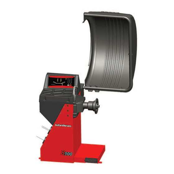
- Page 1 B 100...
- Page 2 fl oor jack being utilized, and has the proper hand and power EST-Tegevdirektor FIN-Operatiivinen johtaja ELL-´M7Z37Q_876[?J ¿73\]\5KÀJ ISL-Starfandi framkvæmdarstjóri LAV-Operatxvais direktors B 100 LIT-Operacij| vadovas }~D-£(•&!•#••" )#&•%••& }ON-Operativni direktor NLD-Operationeel directeur POL-Dyrektor Operatywny RU}-Director Operator SLO-Výkonný riaditeº SLV-Operativni vodja SˆE-Driftledare TUR-‰letme }üdürü HUN-Operatív Igazgató...
- Page 3 CE KONFORMITÄTSERKLÄRUNG DICHIARAZIONE CE DECLARATION CE DECLARACIÓN CE ДЕКЛАРАЦИЯ ЕС DECLARAÇÃO CE Balancer is for indoor use only. Wiring Diagram Schema Elettrico Schaltplan Esquema Eléctrico Schéma électrique Esquema Eléctrico Схема электрических соединений SAVE THESE INSTRUCTIONS John Bean B100 B 100...
- Page 4 DISCLAIMER OF WARRANTIES UPDATING REPORTS AND LIMITATIONS OF LIABILITIES While the authors have taken care in the preparation Wear safety goggles. Release C -_______________- January 2018 of this manual, nothing contained herein: modifi es or alters in any way the standard chapter 5.0 Operations (ALU) - revised.
- Page 5 LIMITES D’APPLICATION DE LA GARANTIE ET VENCIMIENTO DE LA GARANTÍA Y LIMITATIONS DE LA GARANTIE LIMITACIONES DE RESPONSABILIDAD Bien que les auteurs aient accordé la plus grande A pesar de que los autores han prestado la máxima Porter des lunettes de sécurité. Utilice gafas de seguridad.
- Page 6 Safety Safety Important safety precautions relevant to the unit are described in the Safety Booklet, refer to Figure 1 – 1. The Safety Precautions should be fully understood and observed by every operator. We suggest you store (a copy) of the Safety Booklet near the unit, within easy reach of the operator.
- Page 7 Sécurité Seguridad Sécurité Seguridad Les mesures de sécurité importantes relatives à l’unité En el Manual de Seguridad se describen todas las sont décrites dans le Livret de Sécurité et résumées precauciones importantes de seguridad relativas a la Figure 1-1. unidad, consultar la Figura 1 – 1. Chaque opérateur doit totalement comprendre les Las Precauciones de Seguridad deberán ser mesures de sécurité.
- Page 8 Specifi cations 2.0 Specifi cations Power: Power Supply 230V~, 50/60 Hz, 1 ph Power consumption 1,1 A 0,12 KW Motor rating (2x)IEC 127 T 6,3A Mains fuses Measurements: >6 sec. Measuring time >6 sec. Measuring speed <100 rpm <100 rpm Offset 0–250 mm 0–250 mm...
- Page 9 Specifi cations Especifi caciones 2.0 Specifi cations Especifi caciones Données électrices : Potencia eléctrica: Alimentation 230V~, 50/60 Hz, 1 ph Alimentador 230V~, 50/60 Hz, 1 ph Consommation électrique 1,1 A Consumo eléctrico 1,1 A Puissance moteur 0,12 KW 0,12 KW Potencia motor Fusibles (2x)IEC 127 T 6,3A...
- Page 10 Introduction 3.0 Introduction This wheel balancer combines advanced, high- performance technology, robustness and reliability with very simple, user-friendly operation. The low rotation speed of the wheel ensures that this balancer is very safe. It is characterised by a display and input panel which are easy to use and guarantee rapid, intuitive operation.
- Page 11 Introduction Introducción 3.0 Introduction 3.0 Introducción Cette équilibreuse vous offre une technologie avancée Esta equilibradora de ruedas combina una tecnología de haute performance, solidité et fiabilité et son avanzada y de alto rendimiento, robustez y confi anza, opération est très simple et conviviale. con un funcionamiento sencillo y fácil de manejar.
- Page 12 Accessories Accessories Refer to Figure 3.1-1. The standard accessories are: Quick-Release Hub Nut EAA0263G66A Quick-clamping MZV (Ring-Nut) EAA0277G61A Spacer ring EAC0058D08A Universal drum EAC0058D07A Universal drum cushion EAC0058D15A Large cone EAM0005D25A Medium cone EAM0005D24A Small cone EAM0005D23A User Calibration weight EAM0005D40A Weight pliers 00058839000...
- Page 13 Accessoires Accessorios Accessoires Accesorios Se reporter à la Figure 3.1-1. Consultar lao Figura 3.1-1. Les accessoires standard sont: Los accesorios normales son: Manivelle de serrage rapide Tuerca rapida EAA0263G66A EAA0263G66A Ecrou à serrage rapide MZV Flyer MZV EAA0277G61A EAA0277G61A Disque de distance Espaciador EAC0058D08A EAC0058D08A...
- Page 14 Layout 4.0 Layout Refer to Figure 4-1. Functional description of the unit: 1. Display Refer to Chapter 4.1. 2. Input panel Refer to Chapter 4.2. 3. Gauge arm 4. Flange 5. Stub shaft 6. Weight compartments 7. Storage areas for cones and hub nuts 8.
- Page 15 Disposition Disposición 4.0 Disposition Disposición Se reporter à la Figure 4-1. Hágase referencia a la Figura 4-1. Description fonctionnelle de la machine : Descripción funcional de la unidad: 1. Affi chage 1. Pantalla Se reporter au Chapitre 4.1 Consultar Capítulo 4.1. 2.
- Page 16 Layout The display Refer to Figures 4.1-1. 1. Rotation indicators of the correction plane. The indicators show the direction the operator has to rotate the wheel (by hand) after a balancing run. 2. Weight Application Position (WAP) indicator. The indicator will light up when the wheel is in the correct position for weight application.
- Page 17 Disposition Disposición L’affi chage La Pantalla Se reporter à la Figure 4.1-1. Véanse Figuras 4.1-1. 1. Indicateurs de position de masses correctives 1. Indicadores de rotación del plano de corrección. Les indicateurs indiquent la direction vers laquelle Los indicadores muestran la dirección en la que el l’opérateur doit tourner la roue (manuellement) operador deberá...
- Page 18 Layout The input panel Refer to Figure 4.2-1. 1. Diameter key with indicator. Press to select “rim diameter” mode, the current diameter or “dia” value will appear and the unit will beep. The current value will be shown on the display and can be edited.
- Page 19 Disposition Disposición Le Panneau de Données El panel de mandos Se reporter à la Figure 4.2-1. Hágase referencia a la Figura 4.2-1. 1. Touche diamètre avec indicateur 1. Tecla de Diámetro con indicador. Appuyer sur cette touche pour sélectionner le mode Pulse para seleccionar el modo de “diámetro de “diamètre de jante”.
- Page 20 Layout 8. Weight key Press to select the required weight application mode (weight mode), the unit will beep. F+Weight key; activates the Motorcycles wheel balancing Mode. 9. Stop key. Press to stop spinning the wheel. The STOP key also has an emergency stop function.
- Page 21 Disposition Disposición 8. Touche de Masse 8. Tecla de peso y función Moto. Appuyez pour sélectionner le mode de pose des Pulse para seleccionar el modo de aplicación de masses requis (mode de poids), l’unité émet un peso necesario (tipo de rueda). La unidad emitirá bip sonore.
- Page 22 Operation 5.0 Operation This chapter describes how to operate the unit in order to balance a wheel. The standard balancing runs will be described fi rst. In chapter 5.9 and up special modes and functions will be described. Be sure to be familiar with: possible dangers, refer to chapter 1 the unit, refer to chapter 4.
- Page 23 Utilisation Operaciónes 5.0 Utilisation 5.0 Funcionamiento Ce chapitre décrit l’utilisation de la machine pour En este capítulo se describe cómo trabajar con la équilibrer une roue. unidad para equilibrar las ruedas. Les étapes d’équilibrage standard sont décrites en Primero se describe el funcionamiento normal premier.
- Page 24 Operation 5.1 Preparation • The operator should be familiar with the warnings and cautions. • The operator should be qualifi ed to work with the unit. • Always ensure that the wheel guard (when applicable) is lifted and the gauge arm is in its home position (far left position) when the unit has been switched off.
- Page 25 Utilisation Operaciónes Préparation Preparación • L’opérateur doit se familiariser avec les • El operador debe estar familiarizado con las avertissements et les mesures de sécurité. advertencias y precauciones. • L’opérateur doit être formé pour travailler avec la • El operador debe estar califi cado para trabajar con machine.
- Page 26 Operation 5.3 Shutting down Always shut down properly when work is complete: • Remove the wheel from the balancer. • Remove the cones and hub nut from the stub shaft. Check the surfaces (internal and external) of the cones for damage. The condition of the cone is very important for a good balance quality.
- Page 27 Utilisation Operaciónes Arrêt Apagado Apague siempre adecuadamente al fi nal del trabajo: À la fi n du travail compléter toujours les opérations de • Retire la rueda de la equilibradora . façon convenable: • Retire los conos y la virola rápida de la cabeza •...
- Page 28 Operation 5 . 5 W e i g h t a p p l i c a t i o n a n d Measurement methods 5.5.1 Weight application positions Normal Standard positioning of weights, spring weights on rim edges (steel). Symmetrical application of tape weights on Alu 1 rim shoulders (aluminium).
- Page 29 Utilisation Operaciónes 5.5 Modes d’application des masses 5.5 Modos de aplicación de los et relevé des mesures pesos y detección de las medidas 5.5.1 Positions d’application des masses 5.5.1 Posiciones de aplicación de los pesos Normal Posicionamiento normal de los pesos, pesos Normal Positionnement normal des masses, masses de clip en los bordes de la llanta (acero).
- Page 30 Operation 5.5.2 Data required for weight application Normal Offset Distance (rim machine) Nominal rim diameter Nominal rim width Alu 1 Offset Distance (rim machine) Nominal rim diameter Nominal rim width Offset Distance (rim machine) Alu 2 Nominal rim diameter Alu 3 Offset Distance (rim machine) Nominal rim diameter Alu 4...
- Page 31 Utilisation Operaciónes 5 . 5 . 2 D o n n é e s n é c e s s a i r e s p o u r 5.5.2 Datos necesarios para aplicar los l’application des masses pesos Normal Distance de décalage (cercle de la machine) Normal Offset Distancia (máquina llanta) Diamètre nominal de la jante Diámetro nominal de la llanta...
- Page 32 Operation Balancing procedure The unit always has a weight mode automatically selected, refer to the display. Select the appropriate key (1 - Fig.5-6) to scroll through the weight modes continuously. The weight mode currently selected is shown by the illuminated indicator(s). NORMAL Used for steel rims.
- Page 33 Utilisation Operaciónes Procédure d’équilibrage 5.6 Procedimiento de equilibrado La machine a toujours un type de mode d’équilibrage La unidad siempre tiene un tipo de rueda seleccionado sélectionné à l’affi chage. en la pantalla. Seleccione la tecla apropiada (1 Fig.5-6) Sélectionnez la touche appropriée (1 - Fig.5-6) pour para trasladarse por los tipos de rueda continuamente.
- Page 34 Operation 5.6.1 Rim data input Dimension Units diameter: inches (default) or mm. rim width: inches (default) or mm. offset: millimetres. To change the units, refer to Chapter 5.4. 5.6.1.1 Manual Mode Dimensions can be measured by hand and then typed in on the keyboard.
- Page 35 Utilisation Operaciónes 5.6.1 Entrée Paramètres Roue 5.6.1 Introducción de los datos de la rueda Dimension Unités Dimensión: Unidades diamètre: Pouce (défaut) ou mm. diámetro llanta: pulgadas (por defecto) o mm. largeur de jante: Pouce (défaut) ou mm. ancho llanta: pulgadas (por defecto) o mm. déport: millimètres.
- Page 36 Operation 5.6.2 Automatic Mode 5.6.2.1 Distance and Diameter Automatic Entry with measuring arm • Make sure that the measuring arm is in rest position. • Correctly position gauge on rim, so that the arm reference point touches the rim reference point, as shown by the arrow (fi...
- Page 37 Utilisation Operaciónes 5.6.2 Mode Automatique 5.6.2 Modo Automático 5.6.2.1 Introducción Automática de distancia 5.6.2.1 Saisie Automatique de Distance et y diámetro con brazo receptor Diamètre avec bras détecteur Asegurarse de que el brazo de medición esté • • S’assurer que le bras de mesurage est dans la en posición de reposo.
- Page 38 Operation 5.6.2.3 Alu2 and Alu3 (HWM) mode Select this mode for more exact balancing, weight positioning behind spokes or special rims (PAX, TRX, CTS, etc.). When selected, the display shows: HWM1: Two stick-on weights (Fig. 5-12). 5-12 HWM2: Left plane: clip-on weight Right plane: stick-on weight (Fig.
- Page 39 Utilisation Operaciónes 5.6.2.3 Mode des masses Caché 5.6.2.3 Modo Alu2 y Alu3 (HWM) Sélectionner cette fonction pour un équilibrage plus Seleccione este modo para un equilibrio más exacto. correct ; pour la pose des masses derrière les rayons, Los pesos colocados detrás del rayo o llantas ou pour les jantes spéciales (PAX, TRX, CTS, ecc.).
- Page 40 Operation • Establish the following dimensions: Rim diameter of the reference point. Width. If the rim width is ≤ 3”, enter 3”. Offset of the reference point. • After entering the dimensions, spin the wheel (2). • Select the key (3) to activate the STATIC. •...
- Page 41 Utilisation Operaciónes • Indiquez les dimensions suivantes: • Haga constar las dimensiones siguientes: Diamètre de la jante du point de référence. Diámetro de llanta del punto de referencia. Largeur. Si la largeur de la jante est ≤ 3”,entrez 3”. Ancho. Si el ancho de llanta es de ≤ 3”, Offset du point de référence.
- Page 42 Operation Weight application The following weight types and application methods are available: - Clip-on weights. • Always apply by hand at 12 o’clock (Figure 5-17). • The tab should be fi tted on the rim edge. Use the weight pliers to correctly position it. 5-17 - Stick-on weights.
- Page 43 Utilisation Operaciónes Pose des masses Colocación del peso Les types de masses et méthodes de pose Los siguientes tipos de peso y colocación están suivantes sont disponibles : disponibles: - Masses agrafées. - Pesos de sujeción. • Poser toujours manuellement à midi (Figure 5-17). •...
- Page 44 Operation Check spin It is good practice to perform a check spin after applying the weights. • Spin the wheel. If the wheel has been balanced properly, “000” will be displayed for both planes. To check how much imbalance is left: •...
- Page 45 Utilisation Operaciónes Tour de roue de contrôle Giro de control Il est conseillé d’effectuer un lancement de contrôle Se aconseja efectuar una rotación de control después après avoir appliqué les masses. de aplicar los pesos. • Effectuer le lancement de la roue. •...
- Page 46 Operation Special modes Selecting the F (1, figure 5-16) key enables the operator to scroll the following modes in sequence: Split Weight Mode (SWM), Minimisation mode. 5.9.1 Split Weight Mode Selecting is possible only after balancing a HWM wheel that has an imbalance ≥...
- Page 47 Utilisation Operaciónes Modes spéciaux Modos especiales La sélection de la touche F (1, fi gure 5-16) permet à La selección de la tecla “F” (1 Fig. 5-16) permite al l’opérateur de dérouler en séquence: operador pasar en secuencia: Mode Masses Divisées (SWM), Modo Peso Diviso (SWM), Mode Minimisation.
- Page 48 Operation If optimisation is not required, weight minimisation (also known as matching) is possible. For example, when the rim has no shape defects, meaning that wheel imbalance depends exclusively on tyre irregularities. In such cases, the rim imbalance may be positioned relative to the tyre imbalance so that they compensate one another and the machine calculates a minimum correction weight.
- Page 49 Utilisation Operaciónes Si une optimisation n’est pas souhaitée, il est pos- Si no se precisa una optimización, se puede efectuar sible d’obtenir une minimisation des masses (appelée la minimización de los pesos. “matching”). Esto resulta posible cuando la llanta no presenta Ceci est par exemple possible si la jante ne présente defectos de forma, lo cual signifi...
- Page 50 Operation • Press the PRO-MATCH key (2). The OP.1 reading appears. In all fi gures in which the valve symbol appears on the edge of the rim, shift the tyre on the rim then press the PRO-MATCH key (2) to set the valve position (exactly perpendicular to and above the main shaft).
- Page 51 Utilisation Operaciónes Une correction ultérieure n’est plus possible. aconsejamos efectuar la optimización nada más • Démonter le pneu et serrer la jante pour effectuer ejecutar la medición. Pulse la tecla “F” (1) y, a une lancée de compensation. continuación, la tecla PRO-MATCH (2) para activar •...
- Page 52 Operation • Position the valve exactly perpendicular to and above the main shaft. • Press the PRO-MATCH key (2) to acquire the valve position. OP.4 appears. • Press the START key. The measuring run is carried out. After the measuring run two readings are possible: OP.5 - H1 Further optimisation is not recommended, but possible.
- Page 53 Utilisation Operaciónes • Appuyer sur la touche PRO-MATCH (2) pour entrer hínchelo con supresión (unos 3,5 bares) y reduzca la position de la valve. después la presión al valor prescrito. L’affi chage OP.4 apparaît alors. Preste atención al correcto funcionamiento de la línea •...
- Page 54 Operation Silent running cannot be improved. However, it is possible to readjust the tyre relative to the rim to achieve signifi cant weight minimisation (i.e.: smaller balance weights) without having an adverse effect on silent running. Depending on the readings, there are several possibilities for proceeding with the program.
- Page 55 Utilisation Operaciónes atteindre une minimisation considérable des masses d’équilibrage (donc de plus petites masses), sans avoir Ya se ha alcanzado el estado óptimo y por lo tanto no un effet négatif sur la stabilité de marche. puede mejorarse. En fonction des affichages, il existe plusieurs El silencio no puede mejorarse.
- Page 56 Operation indicator and make a double mark on the right side of the tyre exactly perpendicular to and above the main shaft. • Remove the wheel from the machine • Readjust the tyre on the rim until the double mark coincides with the valve.
- Page 57 Utilisation Operaciónes Recommandation de tourner la pneu sur la jante (les En el indicador aparecerá el valor del traits de l’affi chage droit restent allumés). desequilibrio existente en la rueda. Sélection 1 : Tourner le pneu sur la jante (programme Realizar el equilibrado según el indicador.
- Page 58 Operation Weight minimisation program cycle If the rim compensation run was omitted and the F key (1) was pressed to go directly into the minimisation program (reading Un.), proceed as follows. • Clamp the wheel. • Position the valve exactly perpendicular to and above the main shaft.
- Page 59 Utilisation Operaciónes Sélection 2: Interruption d’optimisation En el indicador aparece la sigla === - Un.7 o bien Un.7 - === • Repasser au programme d’équilibrage en appuyant sur la touche STOP (4) et effectuer l’équilibrage Alternativa 2: Interrupción de la optimización suivant les affi...
- Page 60 Operation the tyre be readjusted on the rim. The optimum minimisation condition has been achieved and cannot be improved. Depending on the readings, there are several possibilities for proceeding with the program. These possibilities are described below. Reading === - Un.7 Turn the tyre over on the rim (the left display bars are rotating).
- Page 61 Utilisation Operaciónes Il est recommandé de renverser le pneu sur la jante. === - Un.7 Continuar el trabajo con el programa Un. Se aconseja Un.7 - === voltear el neumático. Poursuivre le programme . Il est recommandé de tourner le pneu sur la jante. Un.7 - === Continuar el trabajo con el programa Un.
- Page 62 Operation (normal program) - Readjust the wheel according to the right direction indicator and make a double mark on the right side of the tyre exactly perpendicular to and above the main shaft. - Remove the wheel from the machine. - Readjust the tyre on the rim until the double mark coincides with the valve.
- Page 63 Utilisation Operaciónes Affi chage Un.7 - === existente en la rueda. Recommandation de tourner la roue sur la jante (les - Ejecute el equilibrado según muestra el indicador. traits de l’affi chage droit restent allumés). Sélection 1: Tourner le pneu sur la jante Con indicación Un.7 - === (programme normal) Invitación a girar el neumático sobre la llanta (las...
- Page 64 Operation 5.9.3 Non-skid function On wheels with a limited weight, skid specifi cations may make it impossible to perform a run at the normal measuring speed. This function may be disabled for a single run: • Hold the START key down while the wheel guard is lowered.
- Page 65 Utilisation Operaciónes 5.9.3 Función Antideslizamiento 5.9.3 Fonction Antidérapage Sur les roues d’un poids contenu, la fonction En las ruedas con peso contenido, la característica de derelèvement du dérapage peut rendre impossible medición del deslizamiento puede imposibilitar el giro le lancement à la vitesse de mesure. a la velocidad de medición.
- Page 66 Operation “MODE” Selecting the operating mode To use the balancer normally you do not need to change the operating mode and the relative states set by the manufacturer. In special cases, however, or if working conditions require it, the operating modes and states can be changed by entering the appropriate codes.
- Page 67 Utilisation “MODE” Operaciónes “MODO” S é l e c t i o n d u m o d e d e 5.10 Selección del modo operativo fonctionnement Durante el ejercicio normal, no es necesario cambiar Pour le fonctionnement normal, il n’est générale- los modos operativos de la equilibradora ni los estados ment pas nécessaire de changer les modes de fonc- programados en fábrica.
- Page 68 Operation “MODE” Code C0 Figure 5-25 setting operating modes preset by the manufacturer No action Set values preset by the manufacturer (state 1 is displayed only briefl y) The operating mode selected can be obtained from the permanent memory. 5-25 Code C1 Figure 5-26 Selecting the defi...
- Page 69 Utilisation “MODE” Operaciónes “MODO” Code C0 Código C0 Fig. 5-25 Etablir les modes de fonctionnement pro- Figura 5-25 Confi guración de los modos operativos grammés par le fabricant programados en fábrica = Aucune action Sin acción = Etablir les valeurs programmées par le fabricant Confi...
- Page 70 Operation “MODE” Code C4 Figure 5-29 Eventual residual clamping device imbal- ance compensation. High precision measuring (This operating mode cannot be stored in the permanent memory). Once compensation has been performed, if the clamp- ing device is changed, this value must be deleted or recalculated using the new device.
- Page 71 Utilisation “MODE” Operaciónes “MODO” Code C4 Código C4 Fig. 5-29 Compensation électrique d’un éventuel Figura 5-29 Compensación del eventual desequilibrio balourd résiduel dans le moyen de serrage. residual de la herramienta de fi jación. Mesure à précision élevée (ce mode ne peut pas être Medición de alta precisión (este modo operativo no se enregistré...
- Page 72 Operation “MODE” Code C8 Figure 5-32 Selecting the threshold value for sup- pressing minor imbalances in grams or oz. The unit of measure depends on the C3 code setting. Ounces: Grammes: Range 0.25 to 2.00 oz Range 5 to 20.0 g Factory-adjusted to 0.25 oz Factory-adjusted to 5 g Read out limit, e.
- Page 73 Utilisation “MODE” Operaciónes “MODO” Code C8 Código C8 Fig. 5-32 Choix de la limite pour la suppression de Figura 5-32 Selección del umbral de supresión de de- faibles balourds, en grammes ou onces. L’unité de sequilibrios mínimos en gramos o en onzas. La unidad mesure (g ou oz) dépend des entrées faites avec C3.
- Page 74 Operation “MODE” Code C14 Figure 5-35 User recalibration (refer to the relevant section). Code C21 Figure 5-36 This displays the program version number and the model number. E.g.: Program version 3.4.18 for Mid. model. 5-35 • to display the program version number release the C key.
- Page 75 Utilisation “MODE” Operaciónes “MODO” Code C14 Código C14 Fig. 5-35 Etalonnage de la machine par l’opérateur Figura 5-35 Calibrado de la máquina efectuado por el (voir la rubrique correspondante). usuario (hágase referencia al capítulo correspondiente). Code C21 Código C21 Fig. 5-36 Lecture du numéro de la version du Figura 5-36 Indicación del número de versión del programme et de la machine.
- Page 76 Maintenance 6.0 Maintenance This unit is designed to operate for a long time. At start-up the operator should check if all indicators and displays light up. If the operator shuts down correctly (Chapter 5.3) at the end of each shift, no further maintenance is required. This unit must not be opened by the operator, apart from following the instructions below.
- Page 77 Entretien Mantenimiento Mantenimiento 6.0 Entretien Esta unidad está diseñada para durar mucho tiempo. Cette machine est conçue pour vous donner un Durante el modo de arranque el operador deberá service de longue durée. Dans le mode de démarrage, comprobar que todos los indicadores y pantallas están l’opérateur doit vérifi...
- Page 78 Maintenance Calibration This chapter describes the calibrations that can be performed by the operator. 6.3.1 User calibration If a number of different measuring runs have to be performed to balance a wheel and the values and positions of the weights have to be changed, it generally means that measuring is not precise.
- Page 79 Entretien Mantenimiento Procédure de calibration Procedimiento de calibrado Ce chapitre contient les procédures de calibration Este capítulo describe las operaciones de calibrado accessibles à l’utilisateur. que puede realizar el operador. 6.3.1 Etalonnage par l’opérateur 6.3.1 Calibración efectuada por el usuario Si plusieurs lancées de mesure sont nécessaires pour équilibrer une roue parce que la grandeur et Cuando la precisión de medición es insufi...
- Page 80 Trouble shooting 7.0 Trouble shooting If a problem arises with the wheel balancer, proceed in the following order to solve the problem: 1. Rethink the last steps taken. Did you work according to the manual? Did the unit work as described and expected? 2.
- Page 81 Dépannage Resolución de problemas 7.0 Dépannage 7.0 Resolución de problemas En cas de problème avec l’équilibreuse, procéder Si ocurre algún problema en la equilibradora, proceda comme suit pour résoudre le problème : en el siguiente orden para resolverlo: 1. Remmemorer les dernières actions effectuées. 1.
- Page 82 Trouble shooting Gauge arm inputs differ from wheel dimensions stated on rim or tyre. 1. Did you position the gauge arm correctly? • Refer to Chapter 5.3.1. 2. Check the offset input of the gauge arm by entering manually. • Refer to the scale on the gauge. •...
- Page 83 Dépannage Resolución de problemas Paramètres de la jauge diffère des dimensions de Las entradas del brazo de medición difi eren de las jante indiquées sur la jante ou le pneu. dimensiones de la llanta indicadas en la misma o en el neumático. 1.
- Page 84 Trouble shooting System messages The wheel balancer can show messages to the operator. These may be error related (E-codes) or warnings (H-codes). The codes will be described in the following chapters. Whenever a code appears: • make a note of it; •...
- Page 85 Dépannage Resolución de problemas Messages de système Mensajes del sistema L’équilibreuse peut afficher des messages pour La equilibradora puede mostrar mensajes al operador. l’opérateur. Ces messages peuvent indiquer des Pueden indicar error (Códigos-E) o advertencias erreurs (Codes E) ou des problèmes de service (Codes (Códigos-H).
- Page 86 Trouble shooting Optimisation / minimisation was not carried out correctly. 1. Wheel was not exactly centred on clamping means for at least one run. 2. Tyre was not centred on rim for at least one run. 3. Valve position was not set and acquired correctly at least once.
- Page 87 Dépannage Resolución de problemas Exécution incorrecte de la lancée d’Optimisation/ La optimización/minimización no se realizó Minimisation. correctamente. 1. La roue n’était pas centrée exactement sur le 1. La rueda no estaba bien centrada en el útil de moyen de serrage au moins une fois pendant les fi...
- Page 88 Trouble shooting A key is jammed. Find and release jammed key. Press STOP or ESC to check the pedal switch. If the error cannot be eliminated, the pedal function is switched off by pressing the STOP key or the ESC key.
- Page 89 Dépannage Resolución de problemas Une touche s’est coincée ou le commutateur de pédale Se ha atascado una tecla. est fermés. Buscar la tecla atascada y desbloquearla. Chercher la touche et la débloquer. O bien: Pulsar STOP o ESC para comprobrar el conmutador Appuyer sur la touche STOP ou ESC pour examiner de pedal.
- Page 90 Trouble shooting H28 - Figure 6-10 The gauge was moved too slowly. Return the gauge the starting position and repeat the operation, bringing the gauge towards the weight application point again. H80 - Figure 6-11 Recalibration was not set up. As a result, it cannot be 6-10 performed by the operator.
- Page 91 Dépannage Resolución de problemas H28 - Figura 6-10 H28 - Figura 6-10 La pige de mesure a été actionée trop lentement. El calibre de medición se movió demasiado lentamente. Remettre la pige en position de repos et l’approcher Volver a colocar el calibre de medición en la posición de nouveau au point de palpage du positionnement inicial y repetir la operación acercando de nuevo el des masses d’equilibrage.
- Page 92 Disposal / Appendices 8. DISPOSING OF THE UNIT To dispose of the equipment at the end of its life, contact the reseller for a quote or for the regulations on disposal which apply to the unit. This symbol indicates that separate collection of waste electrical and electronic equipment is mandatory for scrapping.
- Page 93 Vente / Annexes Eliminación / Anexo 8. VENTE 8. ELIMINACIÓN DE LA UNIDAD Pour la mise à la décharge de l’équipement arrivé Para el desguace del aparato al fi nal de su vida útil, en fi n de vie, contacter le revendeur pour une póngase en contacto con el revendedor para que le offre ou pour connaître les instructions utiles à...
- Page 94 Blank Page...
- Page 95 Appendix: Installation Instructions This appendix describes the installation requirements, installation procedures and checks. Annexe: Instructions d’installation Cette annexe décrit les conditions d’installation, les procédures d’installation et les contrôles. Anexo: Instrucciones para la instalación , los procedimientos y los controles para la instalación. En este anexo se describen los requisitos...
- Page 96 Installation Instructions i. Installation requirements Space requirements The drawing show the minimum safety requirements: The drawing has two sets of dimensions: from the wall to the center of the holes: on the left and top of the drawing from the wall to the outline of the cabinet: on the right and bottom of the drawing Floor requirements The fl...
- Page 97 Instructions d’installation Instrucciones Instalación i. Conditions d’installation i. Requisitos de Instalación Conditions d’espace Le dessin montre les conditions minimum Requisitos de espacio nécessaires à la sécurité: El dibujo muestra los requisitos mínimos necesarios desde el punto de vista de la seguridad: Les croquis a deux séries de dimensions: du mur au centre des trous: à...
- Page 98 Installation Instructions ii Transportation, unpacking and contents Transportation The wheel balancer is supplied on a pallet. • Use a pallet truck (Figure ii-1) to bring the wheel balancer to its working area. Unpacking PREVENT THE STRAPS FROM SPRINGING LOOSE AFTER BEING CUT.
- Page 99 Instructions d’installation Instrucciones Instalación ii Manipulation, déballage et contenu ii Transporte, embalaje y contenidos Manipulation Transporte L’unité est fournie sur une palette. La unidad se suministra en palet. • Utilisez un transpalette (Figure ii-1) pour l’apporter • Utilice una carretilla de palets (Figura ii-1) para à...
- Page 100 Installation Instructions iii Installation procedures Wheel balancer: Refer to the drawing in i for correct wheel balancer positioning. If the wheel balancer needs securing, we recommend fi xing elements with a diameter of 8 mm, quality 8.8 or higher. Supports for Accessories: •...
- Page 101 Instructions d’installation Instrucciones Instalación iii Procédures d’installation Procedimiento de Instalación Unité: Unidad: Voir le graphique correct, section i, pour positionner Consultar el gráfi co, sección i, para colocar la correctement l’équilibreur. Si l’équilibreur doit être equilibradora correctamente. Si hay que sujetar la fi...
- Page 102 Installation Instructions iv Test procedures • Balance a wheel to less than 0.25 oz. (5 grams) per plane. • Perform a User Calibration. See Chapter 6.3.1. v Instructing the operator (Following applies only if a unit is installed by a service Technician) •...
- Page 103 Instructions d’installation Instrucciones Instalación iv Procédures de vérifi cation iv Procedimiento de comprobación • Equilibrer une roue à moins de 0.25 oz. (5 grams) • Equilibrer une roue à moins de 5 grammes (0.25 • Equilibre la rueda con menos de 5 gramos (0.25 •...
- Page 104 Notice: The information contained in this document is subject to change without notice. Snap-on Equipment makes no warranty with regard to present documentation. Snap-on Equipment shall not be liable for errors contained John Bean is a registered trademark. herein or for incidental consequential damages in connection with furnishings, performance, or use of this material.
Need help?
Do you have a question about the B 100 and is the answer not in the manual?
Questions and answers