
Related Manuals for John Bean VPI System


Summary of Contents for John Bean VPI System
- Page 1 FOR: PASSENGER CAR & LIGHT TRUCK WHEELS OPERATION INSTRUCTIONS Form 5787-1 Rev 04/19/2001...
-
Page 3: General Safety Instructions Pages 1
It is assumed that, prior to using the Model VPI System I Wheel Balancer, the operator has a thorough understanding of the wheels and tires being serviced. In addition, it is... - Page 4 IMPORTANT SAFETY INSTRUCTIONS When using this equipment, basic safety precautions should always be followed, including the following: Read all instructions. Do not operate equipment with a damaged power cord or if the equipment has been damaged - until it has been examined by a qualified authorized service technician. If an extension cord is used, a cord with a current rating equal to or more than that of the machine should be used.
-
Page 5: Table Of Contents
John Bean VPI System I Operators Manual TABLE OF CONTENTS General Safety Instructions Pages 1 & 2 Introduction Page 4 Safety Notice Page 4 Balancer Application Page 4 Specifications Page 5 Balancer Features Page 5 Standard Accessories Page 6 Optional Accessories... -
Page 6: Introduction
Read carefully all warnings and instructions of this manual since they provide important information concerning safety and maintenance. 1.2 BALANCER APPLICATION The John Bean wheel balancer model VPI System I is intended to be used as a device to balance car, and light truck wheels within the following range: Maximum wheel diameter : 44”... -
Page 7: Specifications
John Bean VPI System I Operators Manual 1.3 VPI System I SPECIFICATIONS 1.4 FEATURES ACCURACY Computerized digital wheel balancer for car, light truck • Weight placement accuracy to as low as ± .7° wheels. • Weight imbalance accuracy to 2 grams. -
Page 8: Standard Accessories
1.5 STANDARD ACCESSORIES Standard accessories included with the VPI System I are: EAM0003J08A Cone, 85-132 mm / 3.3”-5.2” EAM0003J07A Cone, 71-99 mm / 2.8”-3.9” EAM0003J06A Cone, 56-84 mm / 2.2”-3.3” EAM0003J05A Cone, 43-63 mm / 1.7” - 2.5” 8 - 02040A2... -
Page 9: Dimensions Of The Machine
John Bean VPI System I Operators Manual PRE-INSTALLATION CONSIDERATIONS 1.7 DIMENSIONS OF THE MACHINE Figure 5 - Recommended Work Area 1.9 INSTALLATION INSTRUCTIONS CAUTION! CAREFULLY REMOVE THE BALANCER FROM THE PALLET. Remove the hardware that secures the machine to the pallet and slide the balancer onto the floor where it is to be installed. -
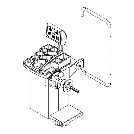
Page 10: Wheel Guard Installation
B. Install the accessory pins (Figure 7). Tighten firmly. Figure 8 2.2 ELECTRIC INSTALLATION ANY ELECTRICAL WIRING MUST BE PER- FORMED BY LICENSED PERSONNEL. ALL SERVICE MUST BE PERFORMED BY AN AUTHORIZED SERVICE TECHNICIAN. Check on the plate of the machine that the electrical Figure 7 specifications of the power source are the same as the machine. -
Page 11: Terminology
John Bean VPI System I Operators Manual 3.0 TERMINOLOGY Figure 9 Before using the wheel balancer it is suggested that 11. Rim Diameter - Enter the rim diameter after press- you become familiar with the terminology and features ing this key. Read the size stated on the tire sidewall. -
Page 12: Balancer Operation
1 and 2 of this manual. There are many types of wheels and John Bean sup- plies adaptors of good quality and durability for the large majority. However if you meet special wheels which may... -
Page 13: Mounting Of Light Truck Wheels
John Bean VPI System I Operators Manual 4.3 MODE SELECTION The majority of balancing takes place in the default 2- plane dynamic mode which is displayed as "2 PL" (location 1). Hammer-on clip weights will be placed on both inside and outside of the rim edge. If required,... -
Page 14: Selecting Operator Preferences
C. ALUMINUM MODES. Balancing using a combina- 4.4 SELECTING OPERATOR PREFERENCES tion of hammer-on and adhesive weights as shown in Figures 17 thru 21. 4.4.1 FINE BALANCING MODE This balancer measures with the maximum precision available all the time, 1g / 0.05 oz, however values be- low 5g / 0.25 oz are shown as zero while in the normal operating mode. -
Page 15: Entering Rim Parameters
John Bean VPI System I Operators Manual 4.5 ENTER RIM PARAMETERS 4.5.3 Measure Rim Width using rim width calipers. Measure wheel where corrective clip-on weight would be applied, Figure 24. Enter the 4.5.1 Rim Distance (offset) - Move the rim off-... -
Page 16: Correcting The Imbalance
4.6 CORRECTION OF THE IMBALANCE NOTE: If this situation is repeated, your machine may be out of calibration and a calibration operation might be required as instructed on page 21. NOTE: Before spinning the wheel make sure proper eye protection is worn by all personnel in the vicinity of D. -
Page 17: Matching Program
The balancer calls for weights in excess of 2 oz. on either plane in the Dynamic mode. The VPI System I computer wheel balancer features a matching program capable of two levels of resolution: Figure 26 - Step 1, valve top, press "F"... - Page 18 NOTE: The "F" button can be pressed as often as nec- essary, with every press the machine updates the memory of the valve position. 5. The machine displays "SPN 2 ". Lower the wheel guard to spin the wheel, when the shaft reaches the balancing speed, machine displays "ACH 2"...
-
Page 19: Optimization Program
John Bean VPI System I Operators Manual 3. Display will read "ACH CHC" for one second. Bal- 7. Lower the wheel guard to spin the shaft. Machine ancing results are checked whether or not the match- displays "ACH 3 " while collecting data. Do not disturb ing balancing has been achieved. -
Page 20: Alu-S Program
7.0 ALU-S MODE This is a mode similar to ALU mode 2 and 3. The differ- ence is that the distance and width parameters are ac- curately defined for a more exacting weight placement, therefore improving the likelihood of a single spin bal- ance. -
Page 21: Spoke Mode
John Bean VPI System I Operators Manual 8.0 Spoke Balancing Mode A standard dynamic balance places compenstation weight in two planes, inner and outer, at the top dead center 180 degrees of each plane of calculated imbalance. Sometimes the outide weight placement may be unsightly on a custom wheel. -
Page 22: Split Weight Mode
9.0 Split Weights - P92 The “Split Weight” function is used to split one large weight to two smaller weights with 60% of original weight and 33.6° away each direction from the original posi- tion. For instance, if the original unbalance weight is 3 oz, the weight is split into two 1.75 oz weights and placed 56.4°... -
Page 23: User Shaft Calibration
John Bean VPI System I Operators Manual 10.0 USER CALIBRATION The VPI System I Balancer features a user calibration program which requires only a few minutes to complete. Perform this procedure when the balancer has been moved, disturbed, or whenever accuracy is questioned. -
Page 24: Distance Gauge Calibration
11.0 Distance Gauge Calibration F80 1. Make sure the SAPE arm is in the home position as shown in (Figure 40). NOTE: Weight tray must be installed. 2. Press the “F” button followed by press- ing the “Up” or “Down” button until the display reads “F”... -
Page 25: Explanation Of "F" Codes
John Bean VPI System I Operators Manual 12.0 EXPLANATION OF PROGRAM CODES 13.0 MAINTENANCE Various functions and features can be programmed to enhance operation. These programs are referred to as “F Codes”. Activate the “F Code” programs by press- BEFORE ANY MAINTENANCE OR RE-... - Page 26 NOTES:...
- Page 27 Notice: The information contained in this document is subject to change without notice. John Bean makes no warranty with regard to this material. John Bean shall not be liable for errors contained herein or for incidental consequential damages in connection with furnishings, performance, or use of this material.
Need help?
Do you have a question about the VPI System and is the answer not in the manual?
Questions and answers