Table of Contents
Advertisement
Advertisement
Table of Contents

Related Manuals for John Bean B 200


Summary of Contents for John Bean B 200
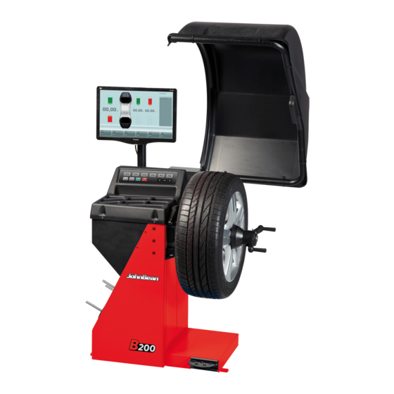
- Page 1 B 200...
- Page 2 fl oor jack being utilized, and has the proper hand and power DEU-Betriebsleiter ALB-Drejtori Operativ BUL-£(•&!•#••" )#&•%••& CES-Výkonný «editel HRV-Operativni direktor DAN-Driftsleder B 200 EST-Tegevdirektor FIN-Operatiivinen johtaja ELL-´ M7 Z37 Q _87 6[ ?J ¿7 3\ ] \ 5K ÀJ ISL-Starfandi framkvæmdarstjóri LAV-Operatx vais direktors LIT-Operacij| vadovas }~D-£(•&!•#••"...
- Page 3 NOTE SULLA DOCUMENTAZIONE - NOTES REGARDING DOCUMENTATION - ITA IMPORTANT SAFETY INSTRUCTIONS - ANMERKUNGEN ZUR DOKUMENTATION NOTAS SOBRE LA DOCUMENTACIÓN - SPA - NOTES SUR LA DOCUMENTATION NOTAS SOBRE A DOCUMENTAÇÃO - POR - ПРИМЕЧАНИЯ ПО ДОКУМЕНТАЦИИ When using this equipment, basic safety precautions should always be followed, in- cluding the following: Product aid publication: Pubblicazione di supporto al prodotto:...
-
Page 4: Table Of Contents
DISCLAIMER OF WARRANTIES UPDATING REPORTS AND LIMITATIONS OF LIABILITIES While the authors have taken care in the preparation Release A -______________- December 2014 of this manual, nothing contained herein: First Release modifi es or alters in any way the standard for new model machine - PCN: 14G0246 terms and conditions of the purchase, lease or... - Page 5 LIMITES D’APPLICATION DE LA GARANTIE ET VENCIMIENTO DE LA GARANTÍA Y LIMITATIONS DE LA GARANTIE LIMITACIONES DE RESPONSABILIDAD Bien que les auteurs aient accordé la plus grande A pesar de que los autores han prestado la máxima attention à la rédaction du présent manuel, aucun atención al redactar este manual, se señala que el élément fi...
-
Page 6: Safety
Safety Safety Important safety precautions relevant to the unit are described in the Safety Booklet, refer to Figure 1 – 1. The Safety Precautions should be fully understood and observed by every operator. We suggest you store (a copy) of the Safety Booklet near the unit, within easy reach of the operator. -
Page 7: Seguridad
Sécurité Seguridad Sécurité Seguridad Les mesures de sécurité importantes relatives à l’unité En el Manual de Seguridad se describen todas las sont décrites dans le Livret de Sécurité et résumées precauciones importantes de seguridad relativas a la Figure 1-1. unidad, consultar la Figura 1 – 1. Chaque opérateur doit totalement comprendre les Las Precauciones de Seguridad deberán ser mesures de sécurité. -
Page 8: 2.0 Specifi Cations
Specifi cations 2.0 Specifi cations Power: Power Supply 230V~, 50/60 Hz, 1 ph 1,1 A Power consumption 0,12 KW Motor rating Mains fuses (2x)IEC 127 T 6,3A Measurements: Measuring time ≥6 sec. ≥6 sec. Measuring speed <200 rpm 200 rpm 0–250 mm Offset 0–250 mm... -
Page 9: Specifi Cations
Specifi cations Especifi caciones 2.0 Specifi cations Especifi caciones Données électrices : Potencia eléctrica: Alimentation 230V~, 50/60 Hz, 1 ph Alimentador 230V~, 50/60 Hz, 1 ph Consommation électrique 1,1 A 1,1 A Consumo eléctrico Puissance moteur 0,12 KW 0,12 KW Potencia motor Fusibles (2x)IEC 127 T 6,3A... -
Page 10: Introduction
Introduction 3.0 Introduction This wheel balancer combines advanced, high- performance technology, robustness and reliability with very simple, user-friendly operation. The wheel guard lowering ensures that this balancer is very safe. The monitor and easy to use controls guarantee rapid and intuitive operativity. The drop down menus, with the lists of all the functions, are on the bottom. -
Page 11: Introducción
Introduction Introducción 3.0 Introduction 3.0 Introducción Cette équilibreuse vous offre une technologie avancée Esta equilibradora de ruedas combina una tecnología de haute performance, solidité et fiabilité et son avanzada y de alto rendimiento, robustez y confi anza, opération est très simple et conviviale. con un funcionamiento sencillo y fácil de manejar. - Page 12 Accessories Accessories Refer to Figure 3.1-1. The standard accessories are: Quick-Release Hub Nut EAA0263G66A Quick-clamping MZV (Ring-Nut) EAA0277D61A Spacer ring EAC0058D08A Universal drum EAC0058D07A Universal drum cushion EAC0058D15A Cone, 87-137 mm / 3.4”-5.4” EAN0003J69A Large cone EAM0005D25A Cone, 96-114 mm / 3.8”-4.5” EAN0005J25A Medium cone EAM0005D24A...
- Page 13 Accessoires Accessorios Accessoires Accesorios Se reporter à la Figure 3.1-1. Consultar lao Figura 3.1-1. Les accessoires standard sont: Los accesorios normales son: Manivelle de serrage rapide Tuerca rapida EAA0263G66A EAA0263G66A Ecrou à serrage rapide MZV Flyer MZV EAA0277D61A EAA0277D61A Disque de distance Espaciador EAC0058D08A EAC0058D08A...
-
Page 14: Layout
Layout 4.0 Layout Refer to Figure 4-1. Functional description of the unit: 1. monitor Refer to Chapter 4.1. 2. Input panel Refer to Chapter 4.2. 3a Internal gauge arm 3b External Detector - Sonar (where provided) 4. Flange 5. Stub shaft 6. -
Page 15: Disposition
Disposition Disposición 4.0 Disposition Disposición Se reporter à la Figure 4-1. Hágase referencia a la Figura 4-1. Description fonctionnelle de la machine : Descripción funcional de la unidad: 1. moniteur monitor Se reporter au Chapitre 4.1 Consultar Capítulo 4.1. 2. Clavier 2. - Page 16 Layout 4.1 The screen Fig. 4-3 Screen with display fi elds Display fi eld of screen Information fi eld Menu fi elds and description of Functions The screen reads out inputs, helpful information, all measured data and possible error codes. Description of display fi...
- Page 17 Disposition Disposición 4.1 Écran Pantalla Fig. 4-3 Écran avec zones d’affi chage Fig. 4-3 Zonas de visualización de la pantalla Zone d’affi chage de l’image Campo de visualización de la pantalla. Zone d’information Campo de informaciónes. Zones de Menu et description des fonctions Campos de Menú...
- Page 18 Layout Fig. 4-5 RIM DATA ENTRY Rim data input Screen. Fig. 4-6 BALANCING Balancing Screen. Fig. 4-7 SETTING Settings Screen. Fig. 4-8 COUNTERS Counters Screen.
- Page 19 Disposition Disposición Fig. 4-5 RIM DATA ENTRY Fig. 4-5 RIM DATA ENTRY Page-écran du Saisie des données de la jante. Pantalla Introducción datos llanta. Fig. 4-6 BALANCING Fig. 4-6 BALANCING Page-écran Equilibrage. Pantalla Equilibrado. Fig. 4-7 SETTING Fig. 4-7 SETTING Page-écran Réglages.
- Page 20 Layout 4.1.2 I Menu Fig. 4-9 Types of menu fi elds The assignment of the menu keys F1 to F6 is shown in the menu fi elds above the relative keys on the screen. The menu keys have different functions and initiate different actions, depending on the program step.
- Page 21 Disposition Disposición 4.1.2 I Menu 4.1.2 I Menu Fig. 4-9 Types de zone de menu Fig. 4-9 Tipos de campos de menú Pour l’affectation des touches de menu F1 à F6, cf. les La asignación de la función del menú correspondiente zones de menu situées au-dessus desdites touches a las teclas de 1 a 6 aparece en el campo de los menús, sur l’écran.
- Page 22 Layout BALANCING “Balancing Screen” Fig. 4-12 For SPOKES selection F2 (a) Select ALU 0 F2 (b) Select ALU 1 F2 (b) F2 (a) F2 (c) Select ALU 2 F2 (d) Select ALU 3 F2 (e) Select ALU 4 F2 (f) Select ALU 5 F2 (c) F2 (d) F2 (e)
- Page 23 Disposition Disposición “Page-écran Equilibrage” “Pantalla Equilibrado” BALANCING BALANCING Fig. 4-12 Fig. 4-12 Pour sélectionner le nombre de RAYONS Seleccione N° RADIOS F2 (a) Sélectionnez ALU 0 F2 (a) Seleccione ALU 0 F2 (b) Sélectionnez ALU 1 F2 (b) Seleccione ALU 1 F2 (c) Sélectionnez ALU 2 F2 (c) Seleccione ALU 2 F2 (d) Sélectionnez ALU 3...
- Page 24 Layout Pictographs – Symbols Piktogramme • Pictographs • Pictogrammes Pictographs are viewed on the screen in all fi elds: In Information fi elds, menu fi elds, and in the display fi eld. P1 Wheel type 1 – standard - nominal size in inches or millimetres P2 Wheel type 2 - motorcycle wheel P3 Alu 0 - normal - Standard balancing mode...
- Page 25 Disposition Disposición Symboles - Pictogrammes Símbolos y Pictogramas Sur l’écran, des pictogrammes sont affi chés dans toutes En la pantalla se visualizan símbolos y pictogramas en les zones d’affi chage: Dans les zones d’information, les todas las zonas: en los campos de información y de zones de menu et dans la zone d’affi...
- Page 26 Layout Piktogramme • Pictographs • Pictogrammes P14 Compensation run carried out P15 Start measuring run by pressing the START key or closing the wheel guard. P16 Calibration weight P17 Provide mark on left tyre side P18 Provide mark on right tyre side. P19 Fit tyre on rim and infl...
- Page 27 Disposition Disposición P14 Lancée de compensation effectuée P14 Lanzamiento de compensación realizado P15 Initialiser une lancer de mesure en appuyant sur P15 Iniciar lanzamiento de medición pulsando la tecla la touche START ou par la fermeture du carter de START o cerrando la protección de la rueda roue.
- Page 28 Layout Key pad Fig. 4-15 Key pad 1 Menu keys (associated with a menu fi eld) 2 ESC key 3 HELP key 4 START key 5 STOP key 6 Key to decrease 7 OK key (to confi rm) 8 Key to increase 4-15 Description of keys 1 Menu keys...
- Page 29 Disposition Disposición Clavier Teclado Fig. 4-15 Clavier Fig. 4-15 Teclado 1 Teclas de menú (cada una atribuida a un campo 1 Touches de menu (attribuées resp. à une zone de de menú) menu) 2 Tecla ESC 2 Touche ESC 3 Tecla HELP 3 Touche HELP 4 Tecla START 4 Touche START...
- Page 30 Layout Main shaft lock Fig. 4-16 Pedal of main shaft lock The main shaft is locked when the pedal is depressed. This facilitates tightening or untightening of the clamping nut and retains the wheel in the correction position for correct fi tting of the balance weights. Note: This lock is designed only to facilitate orientation of the wheel and must not be used for braking the...
- Page 31 Disposition Disposición Blocage de l’arbre principal Freno de paro Fig. 4-16 Pédale de blocage Fig. 4-16 Pedal del freno de parada rueda L’arbre principal est bloqué quand la pédale est Pisando el pedal se bloquea el mandril. Esto facilita actionnée. Cela permet de serrer ou de desserrer apretar o afl...
- Page 32 Layout Help information Help information explains the current action and, in the case of an error code, provides hints for remedy. Display help information Press the HELP key (3, Fig. 4-15). — The fi rst screen with help information appears, e. g. to the screen RIM DATA INPUT (Fig.
- Page 33 Disposition Disposición Textes d’aide Teclas de ayuda Les textes d’aide expliquent l’opération en cours et Los textos de ayuda explican la situación operativa y, donnent des consignes en cas de messages d’erreur aparecen mensajes de error, facilita indicaciones para pour pouvoir trouver un remède. la correspondiente eliminación.
-
Page 34: Operation
Operation Operation This chapter describes how to operate the unit in order to balance a wheel. The standard balancing runs will be described fi rst. From chapter 5.10 on, special functions will be described. Be familiar with: possible hazards, ( unit, ( Clamping a wheel Figure 5-1 illustrates clamping a conventional car... -
Page 35: Utilisation
Utilisation Operaciónes Utilisation Funcionamiento Ce chapitre décrit l’utilisation de la machine pour En este capítulo se describe cómo efectuar el équilibrer une roue. equilibrado de una rueda. Les opérations d’équilibrage standard sont décrites Primero se describe el funcionamiento normal de en premier. - Page 36 Operation Preparation • The operator should be familiar with the warnings and cautions. • The operator should be qualifi ed to work with the machine. • Alwaysensure that the wheel guard is lifted and the gauge arm is in its home position (fully retracted). 5.2.1 Power up •...
- Page 37 Utilisation Operaciónes Préparation Preparación • L’opérateur doit se familiariser avec les • El operador debe estar familiarizado con las avertissements et les mesures de sécurité. advertencias y precauciones. • L’opérateur doit être formé pour travailler avec la • El operador debe estar califi cado para trabajar con machine.
- Page 38 Operation Direct Settings Upon switching on, the unit shows the default unit of measurement in inches. 5.3.1 Changing the Weight Unit Default weight unit setting: ounces. Proceed as follows to change the weight unit, whether you have already spun the wheel or not. •...
- Page 39 Utilisation Operaciónes Réglages directs Confi guraciones Au démarrage, les pouces sont l’unité de mesure de Al encenderse, la unidad muestra las pulgadas como défaut. unidad de medida por defecto. 5.3.1 Commutation Unité de Poids 5.3.1 Cómo cambiar la unidad de peso Unidad de peso por defecto: gramos.
- Page 40 Operation Shutting down Always shut down properly when work is complete: • Remove the wheel from the balancer. • Remove the cones from the stub shaft. Check the surfaces (internal and external) of the cones for damage. The conditions of the cone are very important for a good balance quality.
- Page 41 Utilisation Operaciónes Arrêt Apagado À la fi n du travail compléter toujours les opérations de façon convenable : Apagar siempre adecuadamente la unidad al fi nal del turno de trabajo: • Retirer la roue de l’équilibreuse. • Retirer les cônes de l’embout d’arbre. Vérifi er que •...
- Page 42 Operation 5 . 5 W e i g h t a p p l i c a t i o n a n d Measurement methods 5.5.1 Weight application positions Normal Standard positioning of weights, spring weights on the rim edges (steel). Alu 1 Symmetrical application of stick-on weights on rim shoulders (aluminium).
- Page 43 Utilisation Operaciónes 5.5 Modes d’application des masses 5.5 Modos de aplicación de los et relevé des mesures pesos y detección de las medidas 5.5.1 Positions d’application des masses 5.5.1 Posiciones de aplicación de los pesos Normal Posicionamiento normal de los pesos, Normal Positionnement normal des masses, masses pesos de grapa en los bordes de la llanta à...
- Page 44 Operation 5.5.2 Data required for weight application Normal Offset Distance (rim machine) Rim nominal diameter Rim nominal width Alu 1 Offset Distance (rim machine) Rim nominal diameter Rim nominal width Alu 2 Offset Distance (machine rim) Rim nominal diameter Alu 3 Offset Distance (rim machine) Rim nominal diameter Alu 4...
- Page 45 Utilisation Operaciónes 5 . 5 . 2 D o n n é e s n é c e s s a i r e s p o u r 5.5.2 Datos necesarios para aplicar los l’application des masses pesos Normal Distance écart (machine jante) Normal Distancia Offset (máquina llanta) Diamètre nominal de la jante Diámetro nominal llanta...
- Page 46 Operation 5.6 Data detection mode 5.6.1 Selecting the Type of Vehicle Select the Type of Vehicle before the measuring run. — On the RIM DATA ENTRY screen Fig. 5-11 press the menu key F2 to select the Type of Vehicle. —...
- Page 47 Utilisation Operaciónes 5.6 Mode de saisie des données 5.6 Modo de detección de los datos 5.6.1 Sélection du type de véhicule 5.6.1 Selección del Tipo de Vehículo Il est nécessaire de sélectionner le type de véhicule Es necesario seleccionar el Tipo de vehículo antes del avant la lancée de mesure.
- Page 48 Operation 5.6.2 Manual Mode 5.6.2.1 Width Manual Entry Rim width is entered via the menu keys, the rim diameter can be determined manually . If rim width is not given on the rim, it can be measured on standard rims using the optional rim width callipers (Fig.
- Page 49 Utilisation Operaciónes 5.6.2 Mode Manuel 5.6.2 Modo Manual Introducción manual de Anchura 5.6.2.1 Entrée manuelle de la largeur de jante 5.6.2.1 de la llanta La largeur de la jante est toujours inséré par le clavier, la largeur peut être déterminée manuellement. La anchura de la llanta se entra mediante el teclado, la medida puede determinarse e introducirse manualmente.
- Page 50 Operation 5.6.3 Automatic Mode 5.6.3.1 Distance and Diameter Automatic Entry with measuring arm • Make sure that the measuring arm is in rest position. • Correctly position the measuring arm on rim, so that its reference point touches the rim reference point, as shown by the arrow (Fig.
- Page 51 Utilisation Operaciónes 5.6.3 Mode Automatique 5.6.3 Modo Automático 5.6.3.1 Saisie Automatique de Distance et 5.6.3.1 Introducción Automática de distancia Diamètre avec jauge de mesure y diámetro con brazo receptor • S’assurer que la jauge de mesure est dans la position •...
- Page 52 Operation 5.7 Easy ALU Functions ALU 2P & ALU 3P The Easy Alu function allows to automatically obtain the rim dimensional data: By touching two separate points you can have both ALU 2P e ALU 3Pmodes. In both cases the Easy Alu Toggle (fi g. 5-18) key 5-18 allows to change the displayed selection after touching the rim.
- Page 53 Utilisation Operaciónes 5.7 Fonctionnalité Easy ALU 5.7 Función Easy ALU ALU 2P et ALU 3P ALU 2P y ALU 3P La función Easy Alu permite obtener automáticamente La fonctionnalité Easy Alu permet d’obtenir los datos dimensionales de la llanta: automatiquement les données dimensionnelles de Tocando en dos puntos es posible seleccionar los dos la jante : modos ALU 2P y ALU 3P.
- Page 54 Operation Preliminary verifi cations Preliminary operations: – If necessary perform a compensation run (C4 7.1.1). – Check the wheel is clamped correctly ( 5.1). – Select the Type of Vehicle ( 5.6.1). – Read the rim dimension parameters ( 5.6). 5.8.1 Measuring Imbalance Having completed the preliminary operations, a Measuring run can be launched:...
- Page 55 Utilisation Operaciónes Vérifi cations préliminaires Controles previos Préparatifs : Operaciones previas: – Effectuer une lancée de compensation, si nécessaire – Si es necesario, realizar un lanzamiento de 7.1.1). compensación (C4 7.1.1). – Vérifi er le serrage correct de la roue ( 5.1).
- Page 56 Operation Weight application The following weight types and application methods are available: - Clip-on weights. • Always apply by hand at 12 o’clock (Figure 5-17). • The tab should be fi tted on the rim edge. Use the 5-17 weight pliers to correctly position it. - Stick-on weights.
- Page 57 Utilisation Operaciónes Pose des masses Colocación del peso Les types de masses et méthodes de pose Los siguientes tipos de peso y colocación están suivantes sont disponibles : disponibles: - Masses agrafées. - Pesos de sujeción. • Poser toujours manuellement à midi (Figure 5-17). •...
- Page 58 Operation 5.9.1 Application with gauge arm Weight will be positioned to the left compared to the contact point (A) of Gauge on rim (Figure 5-21). Refer to (Figure 5-22). The gauge arm must be used to apply the stick-on weights. •...
- Page 59 Utilisation Operaciónes 5.9.1 Utiliser la jauge de déport 5.9.1 Uso del brazo medidor La masse sera placée à gauche par rapport El peso se colocará a la izquierda del punto de au point de contact (A) de la jauge sur la jante contacto (A) del Palpador en la llanta (Figura 5-21).
- Page 60 Operation 5.9.2 Check spin It is good practice to perform a check spin after applying the weights. • Spin the wheel. Having fi nished the Test Run, if the wheel is balanced correctly, both the numerical indicators should indicate 0 and an OK should be displayed (Fig. 5-25). Note Note If there is no OK reading, dynamic unbalances below...
- Page 61 Utilisation Operaciónes 5.9.2 Tour de roue de contrôle 5.9.2 Giro de control Il est conseillé d’effectuer un lancement de contrôle Se aconseja efectuar una rotación de control después après avoir appliqué les masses. de aplicar los pesos. • Effectuer le lancement de la roue. •...
- Page 62 Operation 5.10 Behind–the–spokes placement ( Hidden Weight Mode When spoked wheels are balanced, the behind–the– spokes placement mode (also called split weight mode) allows balance weights which would have to be fi tted between two spokes according to the measured unbalance (hence would be visible from outside) to be placed in hidden position behind two spokes adjacent to the unbalance location (see example, Fig.
- Page 63 Utilisation Operaciónes 5.10 Positionnement derrière les 5.10 Posicionamiento pesos rayons ( detrás de los radios ( Hidden Weight Mode Hidden Weight Mode Le programme de mesure positionnement derrière les rayons permet, pour les roues à rayons, de Para las ruedas con radios, el programa de medición positionner les masses d’équilibrage qui, sinon, “Posicionamiento detrás de los radios”...
- Page 64 Operation Note: We suggest you keep the wheel in position with the brake pedal until the selection has been made. — Use the F5 menu key to select the Hidden Weight behind spokes item. The function is now selected and on the right of the screen two balancing gauges are shown instead of one (Fig.
- Page 65 Utilisation Operaciónes Nota Bene: Nota: Il est conseillé de bloquer la roue en position avec Se aconseja mantener la rueda en posición con el le frein de blocage jusqu’à la fi n de la sélection. freno de pedal, hasta que se complete la selección. —...
- Page 66 Operation 5.10.2 Hidden weights placement How to fi t adhesive weights on the left side of the rim disc Clean the fi tting position before attaching the — adhesive weights. Fit adhesive weights on the left side of the rim —...
- Page 67 Utilisation Operaciónes 5.10.2 Fixation d’une masse cachée 5.10.2 Aplicación de pesos ocultos Aplicación del peso adhesivo en el lado izquierdo del canal de la llanta Placer la masse adhésive sur le côté gauche du disque de jante — Antes de fi jar las masas adhesivas, limpiar el punto de aplicación.
- Page 68 Operation 5.11 Optimisation / Weight Minimisation 5.11.1 General Optimisation is a fi ner form of matching. During the opto–ride procedures the rim and tyre are adjusted relative to each other on the basis of different unbalance measurements. This generally means that, where present, lateral and radial run–out and radial and lateral force variations are reduced and thus wheel running conditions optimised.
- Page 69 Utilisation Operaciónes 5.11 Optimisation / Minimisation 5.11 Optimización/ Minimización de des masses los pesos 5.11.1 Généralités 5.11.1 Información general La optimización del desequilibri sirve para maximizar L’optimisation de la stabilité de marche est une forme plus la silenciosidad de la marcha. élaborée du procédé...
- Page 70 Operation 5.11.3 Start optimisation/weight minimisation. Procedure: — Make sure the tyre is correctly mounted on rim and infl ated to specifi ed infl ation pressure (mounting guide rib of the tyre must be correctly seated). — Clamp the wheel. 5-33 —...
- Page 71 Utilisation Operaciónes 5.11.3 Démarrer optimisation de stabilité 5.11.3 Inicio de la optimización o de marche ou minimisation des masses. minimización de los pesos Façon de procéder: Procedimiento: — Vérifi er si le pneu est correctement monté sur la — Comprobar que el neumático esté montado jante (fi...
- Page 72 Operation Fig. 5-36 MINIMISATION “Un.4” (First measuring run of tyre/rim assembly) Readjust the wheel such that the valve is exactly — perpendicular to and above the main shaft. Enter the valve position by pressing menu key — The MINIMISATION “Un.5” screen (Fig. 5-37) is displayed.
- Page 73 Utilisation Operaciónes Fig. 5-36 MINIMISATION “Un.4” Fig. 5-36 MINIMIZACIÓN «Un.4» (1° lanzamiento de medición con neumático) (1ère lancée de mesure de l’ensemble pneu/jante) — Colocar la válvula hasta que quede exactamente Tourner la valve exactement perpendiculairement — perpendicular por encima del mandril. au–dessus de l’arbre principal.
- Page 74 Operation 5.11.4 Start Optimisation Clamp the rim only on the balancer. — Enter correct rim dimensions, or check existing — inputs for correctness. Starting from the main menu, press the menu — key F6 for the Optimisation menu (Fig. 5-33). The OPTIMISATION MENU “OP.1”...
- Page 75 Utilisation Operaciónes 5.11.4 Lancer l’Optimisation de stabilité 5.11.4 Inicio de la optimización de marche — Fijar sólo la llanta. Serrer seulement la jante. — — Entrar las dimensiones correctas de la llanta o Entrer les dimensions de jante correctes ou comprobar si los valores introducidos son los —...
- Page 76 Operation Fig. 5-39 OPTIMISATION “OP.4” (fi rst measuring run of tyre/rim assembly) Clamp the wheel on the balancer. — Readjust the wheel such that the valve is exactly — perpendicular to and above the main shaft. Enter the valve position by pressing menu key F1. —...
- Page 77 Utilisation Operaciónes Fig. 5-39 OPTIMISATION “OP.4” Fig. 5-39 OPTIMIZACIÓN “OP.4” (1ère lancée de mesure de l’ensemble pneu/jante) (1° lanzamiento de medición con neumático) Serrer la roue. — Fijar la rueda. — Tourner la valve exactement perpendiculairement au- — Girar la rueda hasta que la válvula quede exactamente —...
- Page 78 Operation Fig. 5-43 OPTIMISATION “OP.7” Readjust the tyre on the rim such that the single mark — coincides with the valve (use tyre changer). Confi rm by pressing menu key F1. — The OPTIMISATION “OP.8” screen (Fig. 5-44) is displayed. 5-43 Fig.
- Page 79 Utilisation Operaciónes Fig. 5-43 OPTIMISATION “OP.7” Fig. 5-43 OPTIMIZACIÓN “OP.7” Tourner ce repère exactement vers la valve (Orienter Desplazar el neumático sobre la llanta hasta que la marca — — le pneu sur la jante - machine de montage de pneus). aplicada quede exactamente perpendicular por encima Appuyer sur la touche de menu F1 pour confi...
- Page 80 Operation Fig. 5-46a OPTIMISATION “OP.10”, outside Rotate the wheel into marking position following the — arrows. In this position provide a double mark on the tyre outer — side exactly perpendicular to and above the main shaft. Confi rm by pressing menu key F1. —...
- Page 81 Utilisation Operaciónes Fig. 5-46a OPTIMIZACIÓN “OP.10”, exterior Fig. 5-46a OPTIMISATION “OP.10”, extérieur Tourner la roue en position de marquage (fl èches de — — Girar la rueda hasta que esté en la posición de direction). marcado (fl echas de dirección) Placer un repère double dans cette position exactement —...
- Page 82 Operation Reading of error code E9 If E9 is read out, at least one error was made with respect to the sequence of operations when performing optimisation 7.1 System messages). Abort the optimisation program by pressing the STOP — key and, if desired, start optimisation once again. Fig.
- Page 83 Utilisation Operaciónes Affi chage du code d’erreur E9 Al visualizarse el mensaje E9 Si E9 est affi ché, c’est qu’il y a eu au moins une erreur Al visualizarse el mensaje E9, ha habido por lo menos un relative à la séquence de programme lors de la procédure error en el transcurso del programa durante la realización d’optimisation ( 7.1 Messages de système).
-
Page 84: Maintenance
Maintenance 6.0 Maintenance This unit is designed to operate for a long time. If the operator shuts down correctly ( 5.2.4) at the end of each shift, no further maintenance is required. This unit must not be opened by the operator, except in accordance with explicit instructions. -
Page 85: Entretien
Entretien Mantenimiento 6.0 Entretien Mantenimiento Cette machine est conçue pour vous donner un service Esta unidad está diseñada para durar mucho tiempo. de longue durée. Si el operador termina el trabajo correctamente ( Si l’opérateur éteint correctement la machine ( 5.2.4) al fi... - Page 86 Maintenance 6.2 Readjustment by the operator If several measuring runs are necessary to balance a wheel because balance weight size and position have to be adjusted repeatedly, this is often due to insuffi cient measurement accuracy. If this is the case the operator can electronically calibrate the rotating masses on the machine;...
- Page 87 Entretien Mantenimiento 6.2 Etalonnage par l’opérateur 6.2 Calibrado Usuario Si se precisan varios lanzamientos de medición para TS’il faut effectuer plusieurs lancées de mesures afi n equilibrar una rueda porque hace falta corregir varias d’équilibrer une roue, en particulier pour corriger la veces la magnitud y la posición de los contrapesos, la grandeur et la position de la masse d’équilibrage, ce causa suele ser en la mayoría de los casos una falta...
- Page 88 Maintenance Storage When the unit will be stored for a several weeks or longer, prepare the unit correctly: • Shut down the unit properly, refer to Section 5.2.4. • Remove the threaded shaft from the balancer. • Apply a thin layer of non-corrosive oil on all threads and cones.
- Page 89 Entretien Mantenimiento 6.3 Stockage Almacenamiento Lorsque la machine est entreposée pendant plusieurs semaines ou plus, préparer correctement la machine: Cuando se vaya a guardar la unidad durante varias • Eteindre correctement la machine,se reporter au semanas, prepárela adecuadamente: Paragraphe 5.2.4. •...
-
Page 90: Trouble Shotting
Trouble shooting 7.0 Trouble shooting If a problem arises with the wheel balancer, proceed in the following order to solve the problem: 1. Rethink the last steps taken. Did you work according to the manual? Did the unit work as described and expected? 2. -
Page 91: Dépannage
Dépannage Resolución de problemas 7.0 Dépannage 7.0 Resolución de problemas En cas de problème avec l’équilibreuse, procéder Si ocurre algún problema en la equilibradora, proceda comme suit pour résoudre le problème : en el siguiente orden para resolverlo: 1. Remmemorer les dernières actions effectuées. 1. - Page 92 Trouble shooting Gauge arm inputs differ from wheel dimensions stated on rim or tyre. 1. Did you position the gauge arm correctly? • Refer to Chapter 5.3.1. 2. Check the offset input of the gauge arm by entering manually. • Refer to the scale on the gauge. •...
- Page 93 Dépannage Resolución de problemas Paramètres de la jauge diffère des dimensions de Las entradas del brazo de medición difi eren de la jante indiquées sur la jante ou le pneu. dimensión de la llanta refl ejada en la llanta o en 1.
- Page 94 Trouble shooting System messages The wheel balancer can show messages to the operator. These may be error related (E-codes) (e.g.- Figure 7-1) or warnings (H-codes). The codes will be described in the following chapters. Whenever a code appears: • make a note of it; •...
- Page 95 Dépannage Resolución de problemas Messages de système Mensajes del sistema L’équilibreuse peut afficher des messages pour La equilibradora puede mostrar mensajes al operador. l’opérateur. Ces messages peuvent indiquer des Pueden indicar error (Códigos-E) (ej.- Figura 7-1) erreurs (Codes E) (par exemple.- Figura 7-1) ou des o advertencias (Códigos-H).
- Page 96 Trouble shooting Recalibration correction is out of range. During recalibration values above or below the calibration value envisaged were found. This message is only a warning. Use the clamping means supplied with the machine or perform basic calibration (Service). During the fi rst recalibration run the calibration weight was attached by mistake.
- Page 97 Dépannage Resolución de problemas Le terme correctif d’étalonnage est hors de la gamme Factor de corrección del calibrado por el usuario fuera prévue. del ámbito. Pendant l’étalonnage, des valeurs étaient déterminées Durante el calibrado por parte del usuario se tomaron qui dépassent, ou restent inférieures à...
- Page 98 Trouble shooting Wheel silent running cannot be improved with balancing optimisation. Further optimisation is not recommended but is possible. Weight minimisation is recommended, further optimisation does not bring improvements. The SONAR doesn’t work. (S-Version Maschine) The gauge was moved too quickly. Return the gauge at the starting position and repeat the operation, making the gauge approach the weight application point moreslowly.
- Page 99 Dépannage Resolución de problemas Impossible d’améliorer la silence de marche de la roue Resulta imposible mejorar la suavidad de marcha de au moyen d’une Optimisation. la rueda mediante optimización. Déconseillé de continuer l’optimisation qui reste No se recomienda realizar más optimizaciones, pero pourtant possible.
- Page 100 Trouble shooting Wheel acceleration was too slow, or braking was too weak after a measuring run. If the main shaft does not reach the required speed, check that the brake is not activated or the weight of the wheel is too great. In this case: Release the brake.
- Page 101 Dépannage Resolución de problemas La rueda se acelera demasiado poco o, después del L’accélération de la roue a été trop lente, ou bien la lanzamiento, se frena demasiado poco. roue a été freinée trop lentement après une lancée Si el mandril no alcanza el régimen de rotación de mesure.
- Page 102 Trouble shooting 7.3 Changing modes Normal operation usually does not require any modifi cation of the factory-adjusted modes of operation or their factory-adjusted state. In special cases, or if the need arises, different modes of operation or states may be changed by entry of a code. Inputs and readings when a mode of operation is changed (Fig.
- Page 103 Dépannage Resolución de problemas Modes de fonctionnement Modificación de modalidad modifi és operativa Pour le fonctionnement normal, il n’est généralement pas Para el funcionamiento normal no suele ser necesario cambiar las modalidades operativas y sus estados nécessaire de changer les modes de fonctionnement recomendadas por el fabricante.
- Page 104 Trouble shooting Code C0 Setting the factory-adjusted modes of operation 0* = No action Set default values (state 1 is only shown briefl y) The selected mode of operation can be transferred to the permanent memory. Code C1 Selecting the defi nition of the imbalance value in steps Selecting the resolution of unbalance readings in from 0.05 or 0.25 oz.
- Page 105 Dépannage Resolución de problemas Code C0 Código C0 Rétablir les modes de fonctionnement programmés C o n f i g u r a c i ó n d e l o s m o d o s o p e r a t i v o s par le fabricant ( predefi...
- Page 106 Trouble shooting Code C3 Selecting unbalance readings in grammes or ounces, active when the machine is switched on 1* = Readings in ounces 0* = Readings in grammes Readings in grammes Readings in ounces The selected mode of operation can be transferred to the permanent memory.
- Page 107 Dépannage Resolución de problemas Código C3 Code C3 Sélection de l’affi chage du balourd (grammes ou Selección de al indicación de los desequilibrios, onces) qui est active quand on branche la machine en gramos o en onzas, activa la puesta en marcha de la máquina 1* = Affi...
- Page 108 Trouble shooting Code C6 Number of revolutions per measuring run 5 to 25 revolutions possible, factory–set to 10* Note Reducing the number of measurement revolutions will reduce the accuracy of measurement. The selected mode of operation can be transferred to the permanent memory.
- Page 109 Dépannage Resolución de problemas Code C6 Código C6 Nombre de tours par lancée de mesure 5 à 25 tours Número de las vueltas para el lanzamiento possibles reglée dans nos usines à 10* de medición - posibles de 5 a 25 vueltas, preconfi...
- Page 110 Trouble shooting Code C12 Readings of numbers of measuring runs Example: 222,123 measuring runs so far performed (Fig. 7-3). The following counters can be displayed: 1 = Total number of measuring runs 2 = Number of measuring runs where balance quality was considered OK 3 = Number of optimisations or minimisations 4 = Number of measuring runs in service mode...
- Page 111 Dépannage Resolución de problemas Code C12 Código C12 Affi chage des nombres de lancées de mesure aux Contador de los lanzamientos de medición compteurs Ejemplo: 222.123 lanzamientos de medición realizados Exemple: 222.123 lancées de mesure déjà effectuées (Fig. 7-3). (Fig. 7-3). Pueden verse los siguientes contadores: Les compteurs suivants peuvent être affi...
- Page 112 Trouble shooting Code C22 Unclamping of power clamping device locked. Releasing the power clamping device is disabled Applies where another clamping device is fi tted, which is held on the main shaft through the tie rod (e. g. USV, SCA or motor-cycle wheel adaptor “p“). Unclamping enabled Unclamping disabled The mode C22, when changed, is transferred...
- Page 113 Dépannage Resolución de problemas Code C22 Codice C22: Desserrage du moyen de serrage power clamp Bloquear abertura del útil de fi jación Power clamp bloqué. Power clamp. S’applique où un autre moyen de serrage est fi xé, Se puede utilizar si están montados otros dispositivos moyen qui est retenu sur l’arbre principal moyennant de fi...
-
Page 114: Disposing Of The Unit
Disposal / Appendices 8. DISPOSING OF THE UNIT To dispose of the equipment at the end of its life, contact the reseller for a quote or for the regulations on disposal which apply to the unit. This symbol indicates that separate collection of waste electrical and electronic equipment is mandatory for scrapping. -
Page 115: Vente
Vente / Annexes Eliminación / Anexo 8. VENTE 8. ELIMINACIÓN DE LA UNIDAD Pour la mise à la décharge de l’équipement arrivé Para el desguace del aparato al fi nal de su vida útil, en fi n de vie, contacter le revendeur pour une póngase en contacto con el revendedor para que le offre ou pour connaître les instructions utiles à... - Page 116 Blank Page...
-
Page 117: Appendix: Installation Instructions
Appendix: Installation Instructions This appendix describes the installation requirements, installation procedures and checks. Annexe: Instructions d’installation Cette annexe décrit les conditions d’installation, les procédures d’installation et les contrôles. Anexo: Instrucciones para la instalación , los procedimientos y los controles para la instalación. En este anexo se describen los requisitos... - Page 118 Installation Instructions i. Installation requirements Space requirements The drawing show the minimum safety requirements: The drawing has two sets of dimensions: from the wall to the center of the holes: on the left and top of the drawing from the wall to the outline of the cabinet: on the right and bottom of the drawing Floor requirements The fl...
- Page 119 Instructions d’installation Instrucciones Instalación i. Conditions d’installation i. Requisitos de Instalación Conditions d’espace Requisitos de espacio Le dessin montre les conditions minimum nécessaires à la sécurité: El dibujo muestra los requisitos mínimos necesarios desde el punto de vista de la seguridad: Les croquis a deux séries de dimensions: du mur au centre des trous: à...
- Page 120 Installation Instructions ii Transportation, unpacking and contents Transportation The wheel balancer is supplied on a pallet. • Use a pallet truck (Figure ii-1) to bring the wheel balancer to its working area. Unpacking WARNING: PREVENT THE STRAPS FROM SPRINGING LOOSE AFTER BEING CUT. Cut the straps.
- Page 121 Instructions d’installation Instrucciones Instalación ii Manipulation, déballage et contenu ii Transporte, embalaje y contenidos Manipulation Transporte L’unité est fournie sur une palette. La unidad se suministra en palet. • Utilisez un transpalette (Figure ii-1) pour l’apporter • Utilice una carretilla de palets (Figura ii-1) para à...
- Page 122 Installation Instructions iii Installation procedures Wheel balancer: Refer to the drawing in i for correct wheel balancer positioning. If the wheel balancer needs securing, we recommend fi xing elements with a diameter of 8 mm, quality 8.8 or higher. Supports for Accessories: •...
- Page 123 Instructions d’installation Instrucciones Instalación iii Procédures d’installation Procedimiento de Instalación Unité: Unidad: Voir le graphique correct, section i, pour positionner Consultar el gráfi co, sección i, para colocar la correctement l’équilibreur. Si l’équilibreur doit être equilibradora correctamente. Si hay que sujetar la fi...
- Page 124 Installation Instructions Fitting and connecting the monitor Fig. iii-4 Fitting the monitor The 4 screws needed (M4x10) to fi x the VESA support to the monitor are part of the kit supplied. M4x10 (4x) iii-4 Fig. iii-5 Connection of monitor and PC Caution Before connecting the electronic cables turn off the mains switch.
- Page 125 Instructions d’installation Instrucciones Instalación Monter et connecter le moniteur Fijación y Conexión Monitor Fig. iii-4 Montage du moniteur iii-4 Montar el monitor Les 4 vis nécessaires (M4x10) pour fi xer le support Los 4 tornillos necesarios (M4x10) para fijar el VESA sur l’écran font partie du kit.
- Page 126 Blank Page...
- Page 127 Blank Page...
- Page 128 Notice: The information contained in this document is subject to change without notice. John Bean makes no warranty with regard to this material. John Bean shall not be liable for errors contained herein or for incidental consequential damages in connection with furnishings, performance, or use of this material.
Need help?
Do you have a question about the B 200 and is the answer not in the manual?
Questions and answers