
Related Manuals for Huazheng HZ-20AS


Summary of Contents for Huazheng HZ-20AS
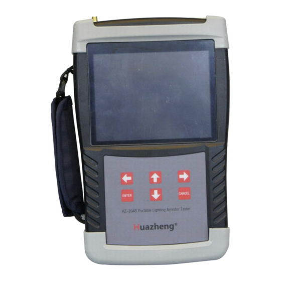
- Page 1 HZ-20AS Portable Lighting Arrester Tester Huazheng Electric Manufacturing (Baoding) Co., Ltd...
- Page 2 (0312) 6775656 to tell you to serve you at all times- Baoding Huazheng Elect ric Manufact ur ing Co. , Lt d. , our company will def initely make you satisf ied !
-
Page 3: Table Of Contents
Contents I.Important............................1 II.Overview.............................2 III.Functions And Fearutres......................2 IV.Technical Index.........................4 V.Measurement And Compensation Principle................. 5 VI.Functions Of Panel Aand Components................7 VII.Operating Instructions......................10 VIII. Test Wiring...........................22 IX.After-sales Service........................25 X.Packing List..........................25... -
Page 4: I.important
I.Important 1. If the instrument is not in use, please turn off the power in time! 2. The rechargeable battery, as consumable part, ought to be well maintained. The effective capacity of rechargeable battery will fall gradually with time passing when the instrument is in use, which shortens the effective time of use. -
Page 5: Ii.overview
distance of wireless communication. 7. When using the wireless test mode, the distance between the host and the voltage collector should be more than 1 meter. Otherwise, the wireless signal of the instrument host can be saturated due to the over-strength of the wireless signal, thus the instrument host will be unable to receive the radio signal sent by the voltage collector. - Page 6 important operation and parameter settings, it displays the tips and help instructions; the top of the screen status bar can display each peripheral working status and test status information. 3.6 The electrical parameters of the three phase zinc oxide arrester can be measured at the same time, and the interphase interference can be compensated automatically.
-
Page 7: Iv.technical Index
the test date and time. 3.15 The test data storage is divided into native storage and U Disk storage. The native storage can store 100 test data, and those date can be transferred into the U disk. U disk storage can save the test data and waveform pictures, with the test data in TXT format and the waveform picture in BMP format,which can be edited and printed directly on the computer. -
Page 8: V.measurement And Compensation Principle
4.4.1 power supply:built-in lithium battery or external charger, charger input 100-240VAC 50Hz/60Hz,output DC8.4V 2A 4.4.2 Charging time: 4 hours 4.4.3 Battery life: host:8h, Voltage Collector: 8h 4.4.4 size of the host: 246mm (length) × 156mm (width) ×62mm (height) 4.4.5 weight of the host:1.0kg (excluding cables) 4.4.6 size of the voltage collector : 115mm (length) ×... - Page 9 non-linearity of the zinc oxide arrester and by the bus voltage harmonic.Compared with Irp, Ir1p is more stable and real, so Ir1p is suggested to be the resistance current index. Both Φ and Ir1p can directly measure the performance of zinc oxide arrester. 5.2 Interphase Interference And Automatic Compensation Principles Fig.2 Interphase Interference...
-
Page 10: Vi.functions Of Panel Aand Components
without automatic compensation, (namely the compensation angle is 0°), and assess the trend of change. VI.Functions Of Panel Aand Components 6.1 Host Panel Diagram And Interface Board Diagram Host panel diagram and interface board diagram are shown in figure 3. 6.1.1 Current input: Phase A, B and C are three input channels, when measured in single phase, currents of phase A, B, and C are channeled from A. - Page 11 Fig.3 Host panel diagram and interface board diagram 1:Current input;1: RS485A; 2:Earth; 2:RS485B; 3:NC. 3:Inductive voltage input; 4: Earth. 5.1.3 LCD screen: Industrial grade 640 * 480 dot matrix high brightness color LCD screen, displaying operation menu, test data, waveform and so on. 5.1.4 Keys: Used for operating the instrument.
- Page 12 not in use in order to save battery power. 6.2 Front And Rear Panels Of The Voltage Collector The front and rear panels of the voltage collector are shown in Figures 4 and 5. 6.2.1 Communication interface: For wired test mode, compatible communication cable is used to connect instrument host reference signal input.
-
Page 13: Vii.operating Instructions
Instrument charger interface, please use compatible charger for the instrument. 6.2.7 Switch: Power switch of voltage collector, please switch off the power supply when it is not in use in order to save battery power. 6.2.8 Voltage input: Reference voltage input is divided into phase A (yellow line),phase B (green line),phase C (red line) and neutral point or ground line (black line). - Page 14 connect wires according to different test ways.Please refer to the "7 test wiring" for wiring instructions under various test modes. When using the wireless test mode, the voltage collector should be placed in a higher position (e.g. on the PT terminal box), which can prolong the wireless communication distance.
- Page 15 paper cover, after the print head axle pressed paper straight, push the print head axle hard back as while as reset the rotary wrench, and push the rotary wrench into the reset. 7.3 Host Operating Instructions Turn on the power switch of the instrument host and enter the boot screen after the instrument is initialized (see figure 6), on which it will display the device model, software version number and hardware version number;...
- Page 16 the received wireless signal strength. When the power is low, the battery symbol flickers. When the wireless signal is not received, the wireless signal strength shows "?", and the alarm will be issued the sound like “di.. di ..di ..” during the test. ●...
- Page 17 ● Test ID : Set the current test number. ● Device ID: The number of the device being tested, which cannot be set. ● Test Mode: The test mode can be wired, wireless and induction. When choosing wireless test mode, the number at the right of the word "wireless" indicates the channel value used by the current wireless module.
- Page 18 Tested Tested Tested Phase A Phase B Phase C Reference Phase ABC 0° 0° 0° Reference Phase A 0° 120° 240° Reference Phase B 240° 0° 120° Reference Phase C 120° 240° 0° Reference Phase A-B 30° 150° 270° Reference Phase C-B 90°...
- Page 19 mode automatically calculates the PT turn ratio by selecting the PT first rated voltage and the PT secondary rated voltage. ● Start Test: After the parameter is set and the cursor is moved to this point;press the "ENTER” key to start the test process and enter the test data display screen.
- Page 20 Fig. 11 Harmonic test data screen Fig. 12 Waveform test data screen ● This symbol is displayed during the test and blinks. ● This symbol is displayed when the test is paused and blinks. Click the "Test" key to enter the test state; click "Pause" key to enter the pause state; Under the test state, the instrument can only switch the display screen, but cannot save data, print,upload and perform other functions.
- Page 21 When using an induction test mode, the Ex is shown to indicate the electric field induced intensity, and the unit is KV/m. ● U1: fundamental voltage effective value; When using induction testing mode, E1 is shown to indicate the fundamental electric field induced intensity. ●...
- Page 22 U1 is the effective value of the fundamental wave voltage When using induction test mode, U1 = 1000V is assumed in the instrument, and the unit of electric capacity is shown as uF·kV and nF·kV. This value is divided by the actual voltage value of the system (kV), and the actual electric capacitance of the zinc oxide arrester under running voltage can be obtained.
- Page 23 the instrument can hold up to 100 test records. Press“←→”key to switch the test record to view. 7.3.6 Real-time clock setting The real-time clock setting screen is shown in figure 15. It is used to set the clock that comes with the instrument. Press "↑ ↓" to adjust the value, press "← →" to move the cursor, press "ENTER"...
- Page 24 Press the "↑ ↓" key to switch the display content. Voltage collector has the function of alarming phase sequence error, when the reference voltage is three-phase (collecting three-phase voltage at the same time), if the three-phase phase sequence is not positive, the alarm information will be displayed and an alarm tone will be sent out.
-
Page 25: Viii. Test Wiring
VIII. Test Wiring 8.1 Notes 8.1.1 Before testing, the instrument host and voltage collector should be reliable grounded (the host is grounded by the black clamp of the current test wire). 8.1.2 Current sampling:For single phase test, the current sampling should be input from phase A channel of the instrument host;and for the three-phase test, the current should be input from phase A, B and C respectively. - Page 26 horizontal symmetry of phase A and C. 8.1.5 Wireless test mode: the voltage collector should be placed in a relatively higher position (for example: on the PT terminal box), which can prolong the distance of wireless transmission and reception. When the wireless signal is weak, the antenna direction can be adjusted appropriately to enhance the wireless signal.
- Page 27 figure 19. Fig. 19 wiring diagram of wireless test mode (simultaneous measurement of three-phase) 8.4 Wiring Instructions Of Induction Test Mode The voltage collector is unnecessary to the induction test mode, the current sampling and the induction electric field sampling can be completed by the host. The induction plate should be placed on the base of phase B arrester, and the position should be symmetric with the arrester of phase A and C, and the sensor plate is perpendicular to the arrester of phase B.
-
Page 28: Ix.after-Sales Service
IX.After-sales Service 9.1 Product warranty forms are provided for the products of our company. Please check and fill out the warranty form on the spot when ordering goods for delivery. 9.2 From the date of purchase, the maintenance fee will not be charged during the warranty period. - Page 29 Current test extension cable Induction test line Wired communication cable Ground wire charger...
Need help?
Do you have a question about the HZ-20AS and is the answer not in the manual?
Questions and answers