
Related Manuals for Huazheng HZ2363


Summary of Contents for Huazheng HZ2363
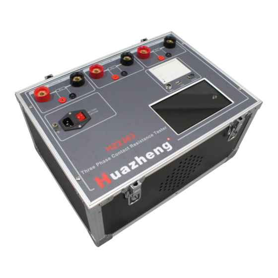
- Page 1 HZ2363 Three Phase Contact Resistance Tester Huazheng Electric Manufacturing (Baoding) Co., Ltd...
- Page 2 (0312) 6775656 to tell you to ser ve you at all times- Baoding Huazheng Elect ric Manufact uring Co. , Lt d. , our company will def initely make you satisf ied!
-
Page 3: Table Of Contents
Contents I.Description.............................1 II.Product Features........................1 III.Technical Parameters....................... 2 IV.Operating Principle........................2 V.Panel Description and Wire Connection................4 VI.Operating Procedure........................5 VII.DC Constant Current Source Function................12 VIII.Mobile Phone Control and Data Transfer (BT communication)......12 IX.Failure Analysis and Trouble Shooting................14 X.Attentions........................... 14 XI.Transportation and Storage.................... -
Page 4: I.description
I.Description HZ2363 Three Phase Contact Resistance Tester is made and contained of advanced high-power switching power supply technology and advanced electronic circuit. It is the dedicated tester for the resistance of high and low switch, cable wire and welding joint. Its current uses national standard GB736 recommended standard DC, can measure the resistance value of being tested object under standard current status. -
Page 5: Iii.technical Parameters
guidance. 18.Chinese input test information:Key in test spot, equipment, person, remark etc, convenient to remark and store test data and printing. 19. Big current cable quick connection: Use latest big current cable port, insert and turn lock III.Technical Parameters Selection 100A 200A 300A... - Page 6 Picture 1, Test Principle Current source have two-end“I+ 、 I- (called ‘I’ shape), supply current for being tested resistance Rx, current value can be read by amperemeter I,voltage of Rx“V+、V-” (called ‘V’ shape) read by voltmeter V. So to calculate resistance value by the measurement of I and V.
-
Page 7: V.panel Description And Wire Connection
V.Panel Description and Wire Connection Picture 2 Picture 2 shows the reference of single-phase tester, please refer to real object. Three-phase tester is totally different. GND:Connecting with land grounding. Power socket:Input AC220V power, switch, fuse inside, light indicator inside switch. Cable connecting point:There have four posts, outer side are two bigger posts connecting with current cable, inner side are two smaller posts connecting with voltage (cable wire), please connect cable matching with red / black / big / small indication, red is positive, black is... -
Page 8: Vi.operating Procedure
computer, also export test data. GPI:GPI port connects with temperature sensor, also used for external cable and alarm light. Attentions: There have some tips and cable connection diagram. Bluetooth:Bluetooth connects with computer for communication. Contact with us for BT APP requirement, not provided with product shipment. - Page 9 (2) Power on After power on, refer to the diagram showing as picture 4. Picture 4, main interface Right up zone: 1 row shows test status (pass / over limit / invalid). Middle side large letter shows resistance, voltage and current. 3 row shows actual test resistivity and actual temperature.
- Page 10 Picture 5, menu item (3)Set test parameters In main interface, press“Setting”button enter parameters interface. See picture 6: Picture 6, Parameters setting interface Do parameters’ settings through drop-down menu by digital key board, Press“OK”button to save parameters in system, not impact by power off and re-open. Current test times and output current :...
- Page 11 Resistance up-limit : can set limit from 0-999999μΩ. When being tested resistance is not over up-limit, test status is“OK”; When being tested resistance is over up-limit, test status shows“over-limit”;If current and voltage cable connect wrong, then shows invalid. Length and section area:set the length and section area to calculate resistivity. Temperature settings :...
- Page 12 Before test, make sure test cable and GND cable is connecting tight. In main interface, press“test”button to do test. Automatically stop test when it is finished. Also press“stop”button to interrupt test. Once finish the test, click to switch and look up test data.
- Page 13 Picture 10 Press“delete”to remove selected file, press“clear”to clear out all files. Insert U disk, then show ‘U disk inserted’ reminding, press“export”to convert file to WORD inside U disk. Already exported file shows“*UP” means not be re-exported, see picture 11, Picture 11 File named by test real time and store as picture 12,...
- Page 14 Picture 12 Convenient for data storage, generation and sharing. (8) Help menu function Background brightness:modify background brightness, idle time and brightness of idle. Cable connection diagram:guide and train onsite operating of cable connection. Time settings:calibrate system time of tester. Maintenance : Factory enter the page to key in password to do maintenance. Unser is not allowed enter it.
-
Page 15: Vii.dc Constant Current Source Function
VII.DC Constant Current Source Function Can output current from 0 to infinite, internal step-up current test, equal to powerful DC constant-current source. Open “DC power”of “function”menu, see picture 19, Picture 19 Please set“periodical time”, “initial current”, “step current”,“max current”. Press“start”to realize periodical step-up current process. - Page 16 Picture 20 Picture 21 Picture 22 Firstly click“connect”to search blue-tooth device, find“BTHL” then click it, key in password“1234”to connect it. Connect blue-tooth successfully, then use APP to control tester. Like click“test”,“stop”,“upload”,“store” etc. after“upload”and“store”, picture 23~25 shows, Picture 23 Picture 24 File is stored in“data”catalog, and named by real test time for convenient storage, report generation and data sharing.
-
Page 17: Ix.failure Analysis And Trouble Shooting
IX.Failure Analysis and Trouble Shooting Symptom Trouble shooting Remark 1Power not connected or Check fuse or switch Must use same open broken No display after type fuse, do not power on Change new fuse or other type instead 2) Fuse not fit well or open re-insert fuse Output current 1) Test path too long caused... -
Page 18: Xii.packing List
XII.Packing list Name Quantity Black Test Line Power Line Print Paper Black Test Line Ground Lead Fuse...
Need help?
Do you have a question about the HZ2363 and is the answer not in the manual?
Questions and answers