Table of Contents
Advertisement
Quick Links
Standalone L-Band Fiber Optic Transmitter
© Copyright 2007
EVERTZ MICROSYSTEMS LTD.
5288 John Lucas Drive,
Burlington, Ontario,
Canada L7L 5Z9
Phone:
905-335-3700
Sales:
sales@evertz.com
Tech Support: service@evertz.com
Web Page:
http://www.evertz.com
Version 1.1 May 2007
The material contained in this manual consists of information that is the property of Evertz Microsystems and is
intended solely for the use of purchasers of the 2405/2407LTA. Evertz Microsystems expressly prohibits the use of
this manual for any purpose other than the operation of the 2405/2407LTA.
All rights reserved. No part of this publication may be reproduced without the express written permission of Evertz
Microsystems Ltd. Copies of this manual can be ordered from your Evertz dealer or from Evertz Microsystems.
2405/2407LTA
Instruction Manual
Fax: 905-335-3573
Fax: 905-335-0909
Advertisement
Table of Contents

Subscribe to Our Youtube Channel
Related Manuals for evertz 2405LTA


Summary of Contents for evertz 2405LTA
- Page 1 Version 1.1 May 2007 The material contained in this manual consists of information that is the property of Evertz Microsystems and is intended solely for the use of purchasers of the 2405/2407LTA. Evertz Microsystems expressly prohibits the use of this manual for any purpose other than the operation of the 2405/2407LTA.
- Page 3 IMPORTANT SAFETY INSTRUCTIONS The lightning flash with arrowhead symbol within an equilateral triangle is intended to alert the user to the presence of uninsulated “Dangerous voltage” within the product’s enclosure that may be of sufficient magnitude to constitute a risk of electric shock to persons. The exclamation point within an equilateral triangle is intended to alert the user to the presence of important operating and maintenance (Servicing) instructions in the literature ac-companying the product.
- Page 4 WARNING Changes or Modifications not expressly approved by Evertz Microsystems Ltd. could void the user’s authority to operate the equipment. Use of unshielded plugs or cables may cause radiation interference. Properly shielded interface cables...
-
Page 5: Table Of Contents
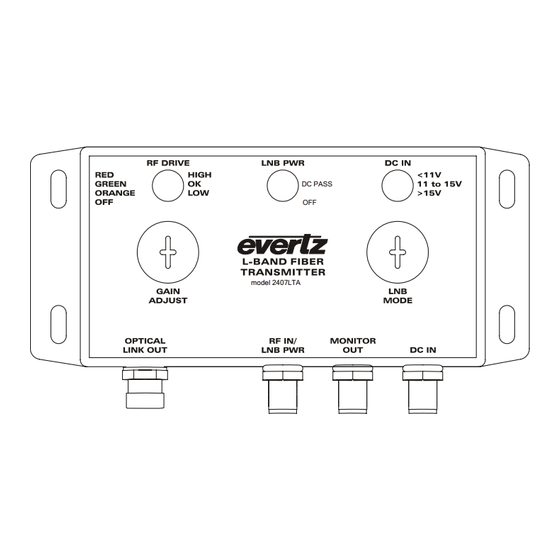
2405/2407LTA Standalone L-Band Fiber Optic Transmitter TABLE OF CONTENTS OVERVIEW............................1 INSTALLATION..........................2 2.1. 2405/2407LTA CONNECTIONS....................3 2.2. CARE AND HANDLING OF OPTICAL FIBER................3 2.2.1. Safety ..........................3 2.2.2. Assembly........................3 2.2.3. Labelling......................... 4 2.2.4. Handling And Connecting Fibers ................... 4 2405/2407LTA SPECIFICATIONS..................... - Page 6 2405/2407LTA Standalone L-Band Fiber Optic Transmitter Figures Figure 1-1: 2405/2407LTA Block Diagram......................1 Figure 2-1: 2407LTA Module ..........................2 Figure 2-2: 2405/2407LTA Mounting Hole Centers and Dimensions – mm [in] ..........2 Tables Table 4-1: LED trip points for RF DRIVE LED for each gain setting..............7 Table 5-1: Gain Adjustment Switch........................
- Page 7 May 07 Information contained in this manual is believed to be accurate and reliable. However, Evertz assumes no responsibility for the use thereof nor for the rights of third parties, which may be effected in any way by the use thereof. Any representations in this document concerning performance of Evertz products are for informational use only and are not warranties of future performance, either express or implied.
- Page 8 2405/2407LTA Standalone L-Band Fiber Optic Transmitter CAUTION If the LNB POWER LED is on or flashing, there will be DC voltage for LNB power at the RF IN connector. This can damage some test equipment. You can turn off the LNB power by switching LNB MODE switch to the OFF position.
-
Page 9: Overview
7708LR receiver and remotely via SNMP/VistaLINK . See 7708LR manual for details ® on the parameters monitored. The 2405LTA does not send this monitoring information down the fiber. Features: • Extended L-Band frequency range - 950 to 2150MHz •... -
Page 10: Installation
2405/2407LTA Standalone L-Band Fiber Optic Transmitter INSTALLATION The 2405/2407LTA comes in a die-cast enclosure with integral mounting flanges. It is recommended that the enclosure be mounted on a flat surface with the connectors facing down. For units with the -WP option that are exposed to the elements, while not required to prevent water ingress into the unit, good outdoor installation practice suggests protecting connectors with a wrap of Scotch 130C rubber tape followed by Scotch Super 88 vinyl tape, or equivalent. -
Page 11: 2405/2407Lta Connections
CARE AND HANDLING OF OPTICAL FIBER 2.2.1. Safety CLASS 1 LASER PRODUCT Background colour: yellow Triangular band: black Symbol: black 2.2.2. Assembly Assembly or repair of the laser sub-module is done only at Evertz facility and performed only by Evertz technical personnel. 2405/2407LTA Revision 1.1... -
Page 12: Labelling
The transmission characteristics of the fiber are dependent on the shape of the optical core and therefore care must be taken to prevent fiber damage due to heavy objects or abrupt fiber bending. Evertz recommends that you maintain a minimum bending radius of 5 cm to avoid fiber-bending loss that will decrease the maximum attainable distance of the fiber cable. -
Page 13: 05/2407Lta Specifications
2405/2407LTA Standalone L-Band Fiber Optic Transmitter 2405/2407LTA SPECIFICATIONS 3.1. RF INPUT Connector: F-type 75 Ω I/O Impedance: Return Loss: >15dB Input Frequency Range: 950MHz – 2150MHz Input Power Range: -20 to –60dBm AGC Hold Range: -20 to –45dBm LNB Voltage: Pass-through from DC input, -0.3VDC Maximum LNB Current: 400mA, current limited... -
Page 14: Environmental
2405/2407LTA Standalone L-Band Fiber Optic Transmitter 3.6. ENVIRONMENTAL Dust and Water Protection: IP65 (-WP version only) Temperature: -40 to +60 deg. C. 3.7. SYSTEM PERFORMANCE (WHEN COMBINED WITH A 7708LR) Frequency Range: 950MHz - 2150MHz Flatness: ±1.5dB @ 950MHz - 2250MHz ±0.25dB @ any 36MHz BW Output Signal Level: (Input signal) + (TX gain) + (RX gain) - (2xOptical Loss) -
Page 15: Status Indicators
2405/2407LTA Standalone L-Band Fiber Optic Transmitter STATUS INDICATORS The 2405/2407LTA module has three LED status indicators on the front of the box to show operational status of the module at a glance. 4.1. RF DRIVE INDICATOR HIGH: The RF DRIVE LED will be RED when the incoming RF signal plus the module gain is overdriving the laser. -
Page 16: Lnb Power Indicator
2405/2407LTA Standalone L-Band Fiber Optic Transmitter 4.2. LNB POWER INDICATOR DC PASS: The LNB PWR LED will be GREEN when the LNB power mode is set to DC PASS. In this mode, DC input from the connected power supply is fed to the LNB. -
Page 17: User Controls
2405/2407LTA Standalone L-Band Fiber Optic Transmitter USER CONTROLS User controls are located behind the two removable hole plugs on the front of the unit. These plugs are threaded and may be removed and installed with a Philips head screwdriver. When installing, ensure that the plugs are snug so as to prevent water ingress, but do not over tighten and distort the rubber washer. -
Page 18: Ps Option
2405/2407LTA Standalone L-Band Fiber Optic Transmitter +PS OPTION When equipped with the +PS option, the 2405/2407LTA will come with an 18VDC, 44W power supply and F-Type cable adapter. This allows the power supply to be connected to the 2405/2407LTA using an appropriate length of coaxial cable with F-Type connectors on either end.
Need help?
Do you have a question about the 2405LTA and is the answer not in the manual?
Questions and answers