Table of Contents
Advertisement
Quick Links
© Copyright 2007 - 2009
EVERTZ MICROSYSTEMS LTD.
5288 John Lucas Drive,
Burlington, Ontario, Canada
L7L 5Z9
Phone:
Sales Fax:
Tech Support Phone:
Tech Support Fax:
Revision 1.5, August 2009
The material contained in this manual consists of information that is the property of Evertz Microsystems and is intended solely for
the use of purchasers of the 2400 series products. Evertz Microsystems expressly prohibits the use of this manual for any
purpose other than the operation of the Routers.
All rights reserved. No part of this publication may be reproduced without the express written permission of Evertz Microsystems
Ltd. Copies of this guide can be ordered from your Evertz products dealer or from Evertz Microsystems.
Stand-Alone L-Band Fiber
Optic Transmitter
Instruction Manual
+1 905-335-3700
+1 905-335-3573
+1 905-335-7570
+1 905-335-7571
2408LT
Internet:
Sales:
Tech Support: service@evertz.com
Web Page:
sales@evertz.com
http://www.evertz.com
Advertisement
Table of Contents

Subscribe to Our Youtube Channel
Related Manuals for evertz 2408LT


Summary of Contents for evertz 2408LT
- Page 1 Revision 1.5, August 2009 The material contained in this manual consists of information that is the property of Evertz Microsystems and is intended solely for the use of purchasers of the 2400 series products. Evertz Microsystems expressly prohibits the use of this manual for any purpose other than the operation of the Routers.
- Page 2 This page left intentionally blank...
- Page 3 IMPORTANT SAFETY INSTRUCTIONS The lightning flash with arrowhead symbol within an equilateral triangle is intended to alert the user to the presence of un-insulated “Dangerous voltage” within the product’s enclosure that may be of sufficient magnitude to constitute a risk of electric shock to persons. The exclamation point within an equilateral triangle is intended to alert the user to the presence of important operating and maintenance (Servicing) instructions in the literature accompanying the product.
- Page 4 WARNING Changes or modifications not expressly approved by Evertz Microsystems Ltd. could void the user’s authority to operate the equipment. Use of unshielded plugs or cables may cause radiation interference. Properly shielded interface cables with the shield connected to the chassis ground of the device must be used.
- Page 5 Evertz products are for informational use only and are not warranties of future performance, either expressed or implied. The only warranty offered by Evertz in relation to this product is the Evertz standard limited warranty, stated in the sales contract or order confirmation form.
- Page 6 2408LT Standalone L-Band Fiber Optic Transmitter CAUTION If the LNB POWER LED is on or flashing, there will be DC voltage for LNB power at the RF INPUT connector. This can damage some test equipment. The user can turn off the LNB power by switching LNB MODE switch to the OFF position.
-
Page 7: Table Of Contents
2408LT Standalone L-Band Fiber Optic Transmitter TABLE OF CONTENTS OVERVIEW............................1 INSTALLATION........................... 2 2.1. 2408LT CONNECTIONS ......................3 2.2. CARE AND HANDLING OF OPTICAL FIBER................3 2.2.1. Safety ..........................3 2.2.2. Assembly......................... 4 2.2.3. Labeling........................... 4 2.2.4. Handling and Connecting Fibers ..................4 2408LT SPECIFICATIONS ......................... - Page 8 Figure 1-1: 2408LT Block Diagram...................... 1 Figure 2-1: 2408LT Module ......................... 2 Figure 2-2: 2408LT Mounting Hole Centers and Dimensions – mm [in] ..........2 Figure 2-3: Reproduction of 2408LT Certification and Identification Label for Models that are Class 1 Laser Products ..................4 Tables Table 4-1: LED Trip Points for RF DRIVE LED for Each Gain Setting ..........
-
Page 9: Overview
2408LT Standalone L-Band Fiber Optic Transmitter OVERVIEW The 2408LT is a fiber optic transmitter used for transporting L-Band satellite signals over a fiber optic cable. The 2408LT accepts one L-Band RF input on an F-Type connector and provides a fiber optic output. -
Page 10: Installation
2408LT Standalone L-Band Fiber Optic Transmitter INSTALLATION The 2408LT comes in a die cast enclosure with integral mounting flanges. It is recommended that the enclosure be mounted on a flat surface with the connectors facing down. For units with the -WP option... -
Page 11: 2408Lt Connections
FC/APC female connector with the optical output from the 2408LT. This connector should be connected to the FIBER IN connector of an appropriate Evertz companion receiver model at the destination end with a suitable fiber optic cable. The 2408LT transmits on the 1310 wavelength unless otherwise indicated by the wavelength label. -
Page 12: Assembly
Background colour: yellow Triangular band: black Symbol: black 2.2.2. Assembly Assembly or repair of the laser sub-module is done only at Evertz facility and performed only by Evertz technical personnel. 2.2.3. Labeling Certification and Identification labels are combined into one label. -
Page 13: 08Lt Specifications
2408LT Standalone L-Band Fiber Optic Transmitter 2408LT SPECIFICATIONS 3.1. RF INPUT Connector: F-type Conductor Range: 21-19 AWG (0.41-0.64 mm 75 Ω I/O Impedance: Return Loss: >15dB Input Frequency Range: 250MHz – 2150MHz Input Power Range: -10 to –60dBm AGC Hold Range: -8 to –38dBm +/- 2dBm... -
Page 14: Physical
2408LT Standalone L-Band Fiber Optic Transmitter 3.5. PHYSICAL Dimensions (with flanges): 5.4"L x 2.4"W x 1.2"H (138mm L x 61mm W x 31mm H) Dust and Water Protection: IP65 (-WP version only) 3.6. SYSTEM PERFORMANCE (WHEN COMBINED WITH A 7708LRA) -
Page 15: Status Indicators
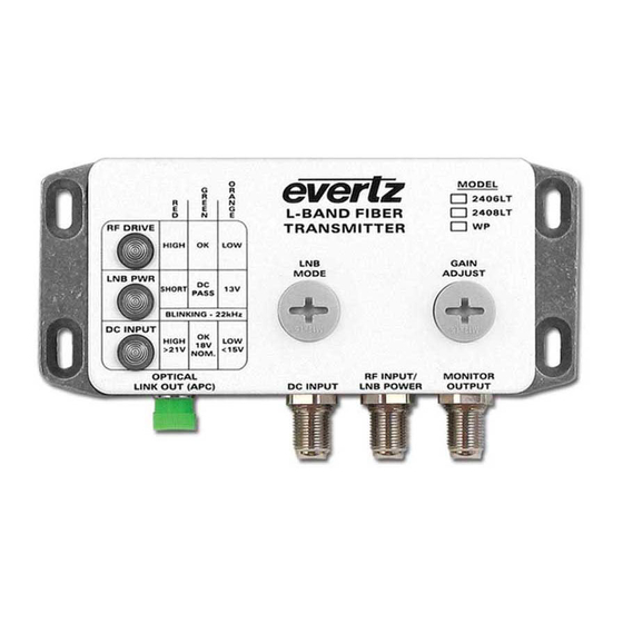
2408LT Standalone L-Band Fiber Optic Transmitter STATUS INDICATORS The 2408LT module has three LED status indicators on the front of the box to show operational status of the module at a glance. 4.1. RF DRIVE INDICATOR HIGH: The RF DRIVE LED will be RED when the incoming RF signal plus the module gain is overdriving the laser. -
Page 16: Lnb Power Indicator
2408LT Standalone L-Band Fiber Optic Transmitter 4.2. LNB POWER INDICATOR SHORT: The LNB PWR LED will be RED if the connected load is in a short circuit or overload condition. DC PASS: The LNB PWR LED will be GREEN when the LNB power mode is set to DC PASS. In this mode, DC input from the connected power supply is fed to the LNB. -
Page 17: User Controls
2 dB gain change, with position 0 being AGC mode. AGC will maintain the output of the 2408LT at a constant level even if the input signal level changes, but remains within the AGC hold range. - Page 18 2408LT Standalone L-Band Fiber Optic Transmitter This page left intentionally blank Page - Revision 1.5...
Need help?
Do you have a question about the 2408LT and is the answer not in the manual?
Questions and answers