Table of Contents
Advertisement
Quick Links
Mainboard User's Manual
This publication, including all photographs, illustrations and
software, is protected under international copyright laws, with all
rights reserved. Neither this manual, nor any of the material
contained herein, may be reproduced without the express written
consent of the manufacturer.
The information in this document is subject to change without
notice. The manufacturer makes no representations or warranties
with respect to the contents hereof and specifically disclaims any
implied warranties of merchantability or fitness for any particular
purpose. Further, the manufacturer reserves the right to revise this
publication and to make changes from time to time in the content
hereof without obligation of the manufacturer to notify any person
of such revision or changes.
Trademarks
IBM, VGA, and PS/2 are registered trademarks of International
Business Machines.
Intel, Pentium/II/III, MMX, and Celeron are registered trademarks
of Intel Corporation.
Microsoft, MS-DOS and Windows 95/98/NT/2000 are registered
trademarks of Microsoft Corporation.
PC-cillin and ChipAwayVirus are trademarks of Trend Micro Inc.
Award is a trademark of Award Software Inc.
A3D is a registered trademark of Aureal Inc.
SuperVoice is a registered trademark of Pacific Image
Communications Inc.
MediaRing Talk is a registered trademark of MediaRing Inc.
3Deep is a registered trademark of E-Color Inc.
Other names used in this publication may be trademarks and are
acknowledged.
Copyright © 2001
All Rights Reserved
M787 Series, V1.1
V133X/May 2001
Advertisement
Table of Contents

Related Manuals for PCchips M787CLR


Summary of Contents for PCchips M787CLR
- Page 1 Mainboard User’s Manual This publication, including all photographs, illustrations and software, is protected under international copyright laws, with all rights reserved. Neither this manual, nor any of the material contained herein, may be reproduced without the express written consent of the manufacturer. The information in this document is subject to change without notice.
- Page 2 Mainboard User’s Manual...
-
Page 3: Table Of Contents
Mainboard User’s Manual Table of Contents Trademarks................I Chapter 1: Introduction..............1 Key Features................2 Package Contents..............5 Static Electricity Precautions..........6 Pre-Installation Inspection............6 Chapter 2: Mainboard Installation..........7 Mainboard Components............8 I/O Ports..................8 Install Memory...............9 Setting Jumper Switches............10 Install the Mainboard............12 Optional Extension Brackets..........13 Install Other Devices............13 Expansion Slots..............15 Chapter 3: BIOS Setup Utility............17 Introduction................17... - Page 4 Mainboard User’s Manual...
-
Page 5: Chapter 1: Introduction
1: Introduction Chapter 1 Introduction This mainboard has onboard VIA Samuel2 1Giga Pro processor with front-side bus speeds of 133MHz. This mainboard uses the VIA VT133 chipset, and integrates a 3D Graphics Accelerator and Ultra DMA 33/66/100 (VT82C686B chip only) function. The mainboard has a built-in AC97 Codec, provides an AMR (Audio Modem Riser) slot to support Audio and Modem application, and has a built-in 10BaseT/100BaseTX Network Interface. -
Page 6: Key Features
Mainboard User’s Manual Key Features The key features of this mainboard include: 1Giga Pro Processor Built-in VIA C3 Samuel2 1Giga Pro CPU Supports up to 133MHz Front-Side Bus Memory Support Two DIMM slots for 168-pin SDRAM memory modules ... - Page 7 1: Introduction AC97 Codec Compliant AC97 2.1 specification Supports 18-bit ADC (Analog Digital Converter) and DAC (Digital Analog Converter) as well as 18-bit stereo full- duplex codec Built-in Ethernet LAN 10BaseT/100BaseTX Ethernet LAN LAN controller integrates Fast Ethernet MAC and PHY compliant with IEEE802.3u 100BASE-TX, 10BASE-T and ANSI X3.263 TP-PMD standards ...
- Page 8 Mainboard User’s Manual Bundled Software PC-Cillin2000 provides automatic virus protection under Windows 95/98/NT/2000 SuperVoice is data, fax and voice communication software MediaRing Talk provides PC to PC or PC to Phone internet phone communication 3Deep delivers the precise imagery and displays accurate color in your monitor ...
-
Page 9: Package Contents
1: Introduction Package Contents Attention: This mainboard series includes two different models. They are M787CLR (LAN Ready) and M787CR (without LAN). Please contact your local supplier for your purchase model. Each model will support different specification, list as below: Model... -
Page 10: Static Electricity Precautions
Mainboard User’s Manual Static Electricity Precautions Components on this mainboard can be damaged by static electricity. Take the following precautions when unpacking the mainboard and installing it in a system. 1. Keep the mainboard and other components in their original static-proof packaging until you are ready to install them. -
Page 11: Chapter 2: Mainboard Installation
2: Mainboard Installation Chapter 2 Mainboard Installation To install this mainboard in a system, follow the procedures in this chapter: Identify the mainboard components Install a CPU Install one or more system memory modules Verify that any jumpers or switches are set correctly Install the mainboard in a system chassis (case) Connect any extension brackets or cables to the mainboard connector headers... -
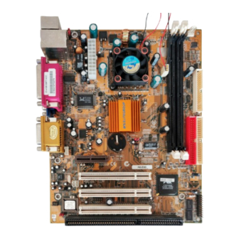
Page 12: Mainboard Components
Mainboard User’s Manual Mainboard Components Use the diagram below to identify the major components on the mainboard. Note: Any jumpers on your mainboard that do not appear in this illustration are for testing only. I/O Ports The illustration below shows a side view of the built-in I/O ports on the mainboard. -
Page 13: Install Memory
2: Mainboard Installation Install Memory The mainboard has two DIMM sockets for system memory modules. You must install at least one memory module in order to use the mainboard. DIMM2 DIMM1 For this mainboard, you must use 168-pin, 3.3V unbuffered PC100 or PC133 SDRAM memory modules. -
Page 14: Setting Jumper Switches
Mainboard User’s Manual Setting Jumper Switches Jumpers are sets of pins which can be connected together with jumper caps. The jumper caps change the way the mainboard operates by changing the electronic circuits on the mainboard. If a jumper cap connects two pins, we say the pins are SHORT. If a jumper cap is removed from two pins, the pins are OPEN. - Page 15 2: Mainboard Installation Jumper JP95: BIOS Write Protect Selector Use this jumper to make the BIOS read-only. Function Jumper Setting Enable (read only) Short Pins 1-2 Disable Short Pins 2-3 Jumper JP96: Keyboard Power On Selector If you enable the keyboard power on feature, you can use hot keys on your keyboard as a power on/off switch for the system.
-
Page 16: Install The Mainboard
Mainboard User’s Manual Install the Mainboard Install the mainboard in a system chassis (case). The board is a micro ATX size mainboard with a twin-tier of I/O ports. Ensure that your case has an I/O cover plate that matches the ports on this mainboard. -
Page 17: Optional Extension Brackets
2: Mainboard Installation Optional Extension Brackets For this mainboard, you can also obtain a USB module extension bracket. Install them by following the steps below. Extended USB Module This module bracket has two USB ports for more USB devices (USB port 3-4). USB1 Header 1. - Page 18 Mainboard User’s Manual Floppy Disk Drive The mainboard ships with a floppy disk drive cable that can support one or two drives. Drives can be 3.5” or 5.25” wide, with capacities of 360K, 720K, 1.2MB, 1.44MB, or 2.88MB. Install your drives and connect power from the system power supply.
-
Page 19: Expansion Slots
2: Mainboard Installation Infrared Port You can connect an infrared port to the mainboard. You can purchase this option from third-party vendors. J1-IR Header VCC 1 NC 2 IRRX 3 GND 4 IRTX 5 1. Locate the infrared port IR header on the mainboard. 2. - Page 20 Mainboard User’s Manual AMR Slot The AMR (Audio Modem Riser) slot is an industry standard slot that allows for the installation of a special audio/modem riser card. Different territories have different regulations regarding the specifications of a modem card. You can purchase an AMR card that is approved in your area and install it directly into the AMR slot.
-
Page 21: Chapter 3: Bios Setup Utility
3: BIOS Setup Utility Chapter 3 BIOS Setup Utility Introduction The BIOS Setup Utility records settings and information about your computer such as the date and time, the kind of hardware installed, and various configuration settings. Your computer uses this information to initialize all the components when booting up and functions as the basis for coordination between system components. -
Page 22: Running The Setup Utility
Mainboard User’s Manual Running the Setup Utility Each time your computer starts, before the operating system loads, a message appears on the screen that prompts you to “Press <DEL> to enter SETUP”. When you see this message, press the Delete key and the Main menu page of the Setup Utility appears on your monitor. -
Page 23: Standard Cmos Features Page
3: BIOS Setup Utility Standard CMOS Features Page Use this page to set basic information such as the date and time, the IDE devices, and the diskette drives. Standard CMOS Features Date (mm:dd:yy) Tue, Jun 12 2001 Item Help Time (hh:mm:ss) 12 : 8 : 59 Menu Level IDE Primary Master... -
Page 24: Advanced Bios Features Page
Mainboard User’s Manual Advanced BIOS Features Page Use this page to set more advanced information about your system. Take some care with this page. Making changes can affect the operation of your computer. Advanced BIOS Features Trend ChipAway Virus Enabled Item Help CPU Internal Cache Enabled... - Page 25 3: BIOS Setup Utility Swap Floppy If you have two floppy diskette drives in your system, this item allows you to swap the assigned Drive drive letters so that drive A becomes drive B, and drive B becomes drive A. Boot Up Floppy If this item is enabled, it checks the geometry of the floppy disk drives at start-up time.
-
Page 26: Advanced Chipset Features Page
Mainboard User’s Manual Advanced Chipset Features Page This page sets some of the parameters of the mainboard components including the memory, and the system logic. Advanced Chipset Features DRAM Timing By SPD Disabled Item Help SDRAM Cycle Length Bank Interleave Disabled Menu Level DRAM Clock... - Page 27 3: BIOS Setup Utility Video RAM When enabled, the graphics card’s local memory will be cached for faster execution. However, if Cacheable any program writes to this memory area, a system error may result. Frame Buffer Size This option determines the frame buffer size shared from the main memory for use by the onboard VGA display.
-
Page 28: Integrated Peripherals Page
Mainboard User’s Manual Integrated Peripherals Page This page sets some of the parameters for peripheral devices connected to the system. Integrated Peripherals On-Chip IDE Channel0 Enabled Item Help On-Chip IDE Channel1 Enabled IDE Prefetch Mode Disabled Menu Level Primary Master Auto Primary Slave Auto... - Page 29 3: BIOS Setup Utility mainboard. Onboard FDD This option enables the onboard floppy disk drive controller. Controller Onboard Serial This option is used to assign the I/O address for the onboard serial port. Port 1 Onboard IR Port This option is used to assign the I/O address for the onboard IR port or disabled.
- Page 30 Mainboard User’s Manual Sound Blaster This feature is used to enable or disable a Sound Blaster card if installed. SB I/O Base This item lets you set the I/O base address for the Sound Blaster card. Address SB IRQ Select This item lets you set the Interrupt Request (IRQ) for the Sound Blaster card.
-
Page 31: Power Management Setup Page
3: BIOS Setup Utility Power Management Setup Page This page sets some of the parameters for system power management operation. Power Management Setup ACPI Function Disabled Item Help Power Management Press Enter PM Control by APM Menu Level Video Off Option Suspend -->... - Page 32 Mainboard User’s Manual MODEM Use IRQ If you want an incoming call on a modem to automatically resume the system from a power- saving mode, use this item to specify the interrupt request line (IRQ) that is used by the modem. You might have to connect the fax/modem to the mainboard Wake On Modem connector for this feature to work.
-
Page 33: Pnp/Pci Configurations Page
3: BIOS Setup Utility PnP/PCI Configurations Page This page sets some of the parameters for devices installed on the PCI bus and devices that use the system plug and play capability. PnP/PCI Configurations PNP OS Installed Item Help Reset Configuration Data Disabled Menu Level Resources Controlled by... - Page 34 Mainboard User’s Manual the IRQ Resources sub-menu. PCI/VGA Palette This item is designed to overcome some problems that can be caused by some non-standard VGA Snoop cards. This board includes a built-in VGA system that does not require palette snooping so you must leave this item disabled.
-
Page 35: Hardware Monitor Page
3: BIOS Setup Utility Hardware Monitor Page This page sets some of the parameters for the hardware monitoring function of this mainboard. CMOS Setup Utility – Copyright (C) 1984 – 2001 Award Software Hardware Monitor Current CPU Temp. Item Help Current System Temp. -
Page 36: Frequency/Voltage Control Page
Mainboard User’s Manual Frequency/Voltage Control Page This page sets some of the parameters for frequency and voltage control. Frequency/Voltage Control Auto Detect DIMM/PCI Clk Enabled Item Help Spread Spectrum Disabled Menu Level Auto Detect DIMM/ When this item is enabled, BIOS will disabled the clock signal of free DIMM and PCI slots. -
Page 37: Load Optimized Defaults
3: BIOS Setup Utility Load Optimized Defaults If you select this item and press Enter, a dialog box appears. If you press Y, and then Enter, the Setup Utility loads a set of fail-safe default values. These default values are not very demanding and they should allow your system to function with most kinds of hardware and memory chips. - Page 38 Mainboard User’s Manual discard changes and exit, or press N to return to the setup main menu.
-
Page 39: Chapter 4: Software & Applications
4: Software & Applications Chapter 4 Software & Applications Introduction The support software CD-ROM that is included in the mainboard package contains all the drivers and utility programs needed to properly run our products. Below you can find a brief description of each software program, and the location for your mainboard version. - Page 40 Mainboard User’s Manual Note: The correct path name for each software driver is provided, where D: identifies the CD-ROM drive letter – modify if necessary. Bus Master IDE Driver The IDE Bus Master Drivers allows the system to properly manage the IDE channels on the mainboard.
-
Page 41: Auto-Installing Under Windows 98
4: Software & Applications PC-Cillin Software The PC-cillin software program provides anti-virus protection for your system. Find the software here: D:\PC-CILLIN\ Auto-installing under Windows 98 The support software CD-ROM disc loads automatically under Windows 98. When you insert the CD-ROM disc in the system CD-ROM drive the Autorun feature will automatically bring up the install screen. - Page 42 Mainboard User’s Manual Installing Software with Auto Setup To install support software for the system board follow this procedure: 1. Click on the Setup button. The install program will load and display the following screen. Click the Next button. 2. Select the items that you want to setup by clicking on it (the default options are recommended).
Need help?
Do you have a question about the M787CLR and is the answer not in the manual?
Questions and answers