Table of Contents
Advertisement
Quick Links
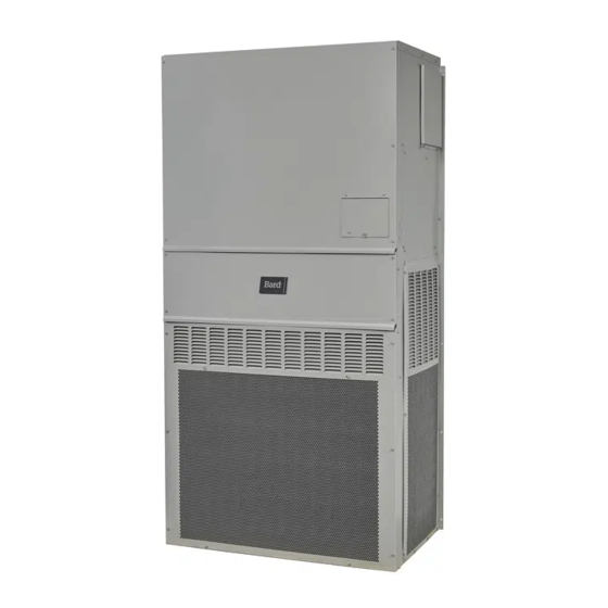
INSTALLATION INSTRUCTIONS
Wall Mount Heat Pump
C36HY-A
C36HY-B
C36HY-C
Bard Manufacturing Company, Inc.
Bryan, Ohio 43506
www.bardhvac.com
11EER CH Series
Models:
C42HY-A
C42HY-B
C42HY-C
C48HY-A
C48HY-B
C48HY-C
Manual:
Supersedes: 2100-769
Date:
C60HY-A
C60HY-B
C60HY-C
2100-769A
6-21-23
Page
1 of 50
Advertisement
Table of Contents
Troubleshooting

Subscribe to Our Youtube Channel
Related Manuals for Bard CH Series


Summary of Contents for Bard CH Series
- Page 1 INSTALLATION INSTRUCTIONS 11EER CH Series Wall Mount Heat Pump Models: C36HY-A C42HY-A C48HY-A C60HY-A C36HY-B C42HY-B C48HY-B C60HY-B C36HY-C C42HY-C C48HY-C C60HY-C Bard Manufacturing Company, Inc. Manual: 2100-769A Bryan, Ohio 43506 Supersedes: 2100-769 Date: 6-21-23 www.bardhvac.com Page 1 of 50...
-
Page 2: Table Of Contents
CONTENTS Safety Instructions ..........4 Defrost Cycle ............. 31 General Information ..........10 Low Pressure Switch Bypass Operation ..... 32 Shipping Damage ..........10 High Pressure Switch Operation ....... 33 Additional Publications ........10 Vent Connection Plug .......... 33 Heat Pump Wall Mount Model Nomenclature ..11 Pressure Service Ports ........ - Page 3 TABLES Table 1 Clearance Required for Service Access and Adequate Condenser Airflow ... 18 Table 2 Minimum Clearances Required to Combustible Materials ......18 Table 3 Field Supplied Controls – Sequence of Operation ......26 Table 4 Wall Thermostats ........ 26 Table 5 Humidity Controls .......
-
Page 4: Safety Instructions
SAFETY INSTRUCTIONS READ ALL INSTRUCTIONS BEFORE USE Your safety and the safety of others are very important. We have provided many important safety messages in this manual and on your appliance. Always read and follow all safety messages. ANSI Z535.5 Definitions: DANGER: Indicate[s] a hazardous situation which, if not avoided, will result in death or serious injury. - Page 5 WARNING CAUTION Sharp metallic edges. Electrical shock hazard. Have a properly trained individual perform Take care and wear appropriate protective these tasks. devices to avoid accidental contact with sharp edges. Failure to do so could result in electric shock Failure to do so can result in personal injury. or death.
- Page 6 IMPORTANT SAFETY INSTRUCTIONS WARNING To reduce the risk of explosion, fire, death, electric shock, scalding or injury to persons when using this product, follow basic precautions, including the following: GENERAL · The equipment covered in this manual is to be installed by trained, experienced service and installation technicians.
- Page 7 INSTRUCTIONS DE SÉCURITÉ LIRE TOUTES LES INSTRUCTIONS AVANT UTILISATION Votre sécurité et celle des autres sont très importantes. Nous avons fourni de nombreux messages de sécurité importants dans ce manuel et sur votre appareil. Lisez et suivez toujours tous les messages de sécurité. Définitions ANSI Z535.5 : DANGER : Indique une situation dangereuse qui, si elle n’est pas évitée, entraînera certainement la mort ou des blessures graves.
- Page 8 AVERTISSEMENT ATTENTION Arêtes métalliques vives. Risque de choc électrique. Ces tâches doivent être réalisées par une Faites attention et portez des dispositifs de personne parfaitement qualifiée et formée. protection appropriés pour éviter tout contact accidentel avec des arêtes vives. Le non-respect de cette consigne peut entraîner Le non-respect de cette consigne peut entraîner des chocs électriques ou la mort.
- Page 9 INSTRUCTIONS DE SÉCURITÉ IMPORTANTES AVERTISSEMENT Pour réduire le risque d’explosion, d’incendie, de décès, de choc électrique, d’échaudure ou de blessures pour les personnes lors de l’utilisation de ce produit, suivez les précautions de base, notamment les suivantes : GÉNÉRALITÉS · L’équipement couvert dans ce manuel doit être installé par des techniciens de service et d’installation formés et expérimentés.
-
Page 10: General Information
GENERAL INFORMATION Additional Publications Shipping Damage These publications can help when installing the heat Upon receipt of equipment, the carton should be pump. They can usually be found at the local library checked for external signs of shipping damage. If or purchased directly from the publisher. -
Page 11: Heat Pump Wall Mount Model Nomenclature
Heat Pump Wall Mount Model Nomenclature – 0Z X UNIT SERIES ACCESSORIES & 2 Stage Quiet Climate CONTROL OPTIONS X – Standard Controls NOMINAL CAPACITY (HPS, LPS, CCM) 36 – 3.0 Ton E – Low Ambient Control 42 – 3.5 Ton Q –... -
Page 12: Duct Work
5/8". Any grille that meets with 5/8" louver criteria may be FIGURE 2 used. It is recommended that Bard Return Air Grille Removing Left Filter Kits RG5 or RFG5 be installed when no return duct is used. -
Page 13: Switching Filter Sizes
FIGURE 3 2. Locate the filter support brackets and remove the four (4) screws holding them to the top of the Removing Second Filter control panel (see Figure 6). FIGURE 6 Remove Four Screws 3. Reverse the order for new filter installation. 3. -
Page 14: Fresh Air Intake
Fresh Air Intake 6. Install the right 2" filter first followed by the left filter (see Figures 9 and 10). All units are built with fresh air inlet louvers punched NOTE: When installing new filters, make sure that in the side grilles. airflow arrows on filters point up. -
Page 15: Installation
INSTALLATION Basic Installation Design and Portable or modular building placement must be in a way that the wall mount units have a constant supply Application Planning of outdoor air for proper unit operation. Make sure that Successful unit installations require proper planning the service panels of the unit are accessible. -
Page 16: Ducted Applications
5/8". It is recommended that a unit supply and return flanges before unit installation to Bard Return Air Grille Kit is installed that is designed help with duct connections inside the structure. Supply specifically for the wall mount product. Contact the and return ducts must be properly sized for the design local Bard distributor or visit www.bardhvac.com for... -
Page 17: Materials/Tool List
Materials/Tools List is not required. Review all requirements listed on unit labels and on serial plate located on the side Additional hardware and miscellaneous supplies are of the unit. needed for installation. These items are field supplied and must be sourced before installation. This list also 2. -
Page 18: Figure 12 Vent Installation/Removal Clearance Required
TABLE 1 TABLE 2 Clearance Required for Service Access and Minimum Clearances Required Adequate Condenser Airflow to Combustible Materials Left Right Discharge – Model Supply Air Duct (1st 3') Cabinet Model Side* Side* Front C36HY C36HY C42HY C42HY 1/4" 0" 20"... -
Page 19: Figure 13 Unit Dimensions
FIGURE 13 Unit Dimensions Supply Return Width Depth Height C36HY 42.00 25.52 84.75 9.88 29.88 15.88 29.88 43.88 12.63 39.06 30.06 43.25 26.94 55.59 52.59 8.82 43.00 1.44 16.00 1.88 10.50 12.00 C42HY C48HY 42.00 25.52 92.88 9.88 29.88 15.88 29.88 43.88 12.63 45.00 30.06 49.25 35.06 61.72 58.72 8.82 43.00 1.44 16.00 10.00 13.88 15.43 C60HY All dimensions are in inches. -
Page 20: Figure 14 Mounting Instructions
FIGURE 14 Mounting Instructions SEAL WITH BEAD UNITS REQUIRED DIMESIONS OF CAULKING ALONG REQUIRED DIMESIONS TO ENTIRE LENGTH OF MAINTAIN 1/4" MIN. CLEARANCE 30 1/2 10 1/2 6 1/4 1 1/4 29 3/4 16 1 7/8 TOP. FROM COMBUSTIBLE MATERIALS C36HY-C42HY RAIN FLASHING UNITS... -
Page 21: Figure 15 Electric Heat Clearance
FIGURE 15 Electric Heat Clearance Typical Building Wall Frame Outside Sheeting Inside Sheeting Supply Air Unit Duct 1/4" Min. Supply Air Duct See Note Below Flange of Wall Note: Side section view of supply air duct for wall mounted unit showing 1/4"... -
Page 22: Figure 16 Wall Mounting Instructions
FIGURE 16 Wall Mounting Instructions See Figure 14 Mounting Instructions FACTORY SUPPLIED RAIN FLASHING. WALL STRUCTURE MOUNT ON UNIT BEFORE INSTALLATION SUPPLY AIR OPENING RETURN AIR OPENING WOOD OR STEEL SIDING BOTTOM MOUNTING BRACKET. MOUNT ON WALL BEFORE INSTALLING UNIT. CONCRETE BLOCK WALL INSTALLATION WOOD FRAME WALL INSTALLATION SIDE VIEW... -
Page 23: Figure 18 Common Wall Mounting Installations
FIGURE 18 Common Wall Mounting Installations Non-Ducted Installations Ducted Installations Unit is Unit is Ceiling Ceiling sealed to sealed to wall. wall. Supply Air Duct Adjustable Supply Grille Optional Dropped Ceiling Wall Wall Mount Mount Fixed Blade Unit Unit Fixed Blade Return Grille Return Grille Indoor Area Indoor Area... -
Page 24: Wiring - Main Power
Wiring – Main Power All models are suitable only for connection with copper wire. Each unit and/or wiring diagram will be marked “Use Copper Conductors Only”. These instructions WARNING must be adhered to. Refer to the National Electrical Code (NEC) for complete current carrying capacity data on the various insulation grades of wiring material. -
Page 25: Wiring - Low Voltage
If the unit is being installed with any ventilation package, a Bard LAC kit must be installed. Failure to utilize an For low voltage wiring, an 18 gauge copper, color-coded LAC with any heat pump can cause coil freeze up. -
Page 26: Table 3 Field Supplied Controls - Sequence Of Operation
TABLE 3 TABLE 5 Field Supplied Controls – Sequence of Operation Humidity Controls Fan Only Energize G Part Number Predominate Features Cooling Mode 1st Stage Energize G, Y1 8403-038 SPDT switching, pilot duty 50VA @ 24V; Cooling Mode 2nd Stage Energize G, Y1, Y2 (H600A1014) Humidity range 20-80% RH... -
Page 27: Figure 20 Thermostat Connections
FIGURE 20 Thermostat Connections Units With Dehumidification 8403-038 Mechanical Humidistat T6 Pro 8403-090 or 8403-092 8403-047 or 8403-100 Electronic Humidistat Optional CO2 Controller Bard Part #8403-096 24VAC CO2 OUT TEMP-OUT Unit Low B/W1 Voltage Term. Strip 12-Pin Vent Plug ALL VENT OPTIONS PLUG IN HERE If not equipped with a ventilation option to plug in, a jumper plug must be installed. -
Page 28: Figure 21 Thermostat Connections
FIGURE 21 Thermostat Connections Thermostat #8403-081 or #8403-083 T6 Pro 8403-090 or 8403-092 Optional CO2 Controller Bard Part #8403-096 24VAC CO2 OUT TEMP-OUT Unit Low B/W1 Voltage Term. Strip 12-Pin Vent Plug ALL VENT OPTIONS PLUG IN HERE If not equipped with a ventilation option to plug in, a jumper plug must be installed. -
Page 29: Start Up
All C**HY wall-mounted heat pump series models Topping Off System Charge are supplied with a remote reset for the high and low If a leak has occurred in the system, Bard pressure switch. If tripped, the pressure switch may be Manufacturing recommends reclaiming, evacuating reset by turning the thermostat off then back on again. -
Page 30: Phase Monitor
Service Hints However, three phase compressors will rotate in either direction depending upon phasing of the power. 1. Caution owner/operator to maintain clean air filters Since there is a 50-50 chance of connecting power at all times and also not to needlessly close off in such a way as to cause rotation in the reverse supply and return air registers. -
Page 31: Heating Stage 2
If the unit is being installed with any ventilation shorting instrument from the SPEEDUP terminals. package, a Bard LAC kit must be installed. Failure Otherwise the timing will remain accelerated and to utilize an LAC with any heat pump can cause coil run through the 1-minute minimum defrost length freeze up. -
Page 32: Low Pressure Switch Bypass Operation
compressor could stop due to the high pressure control timing period and shorting out the SPEEDUP terminals opening because of high pressure condition created for a few seconds can do this. by operating in the cooling mode with outdoor fan off. Low Pressure Switch Bypass Operation Pressure will rise rapidly as there is likely no actual The control has a selectable (SW1) low pressure switch... -
Page 33: High Pressure Switch Operation
High Pressure Switch Operation The control has a built-in lockout system that allows the unit to have the high pressure switch trip up to two times in 1 hour and only encounter a “soft” lockout. A “soft” lockout shuts the compressor off and waits for the pressure switch to reset, which at that point then allows the compressor to be restarted as long as the 5-minute short cycle timer has run out. -
Page 34: Service
SERVICE Solid State Heat Pump Control NOTE: If there was no power to 24 volt transformer, Troubleshooting Procedure the compressor and outdoor fan motor will not start for 5 minutes. This is because of the 1. NOTE: A thorough understanding of the defrost compressor short cycle protection. -
Page 35: Checking Temperature Sensor Outside Unit Circuit
Checking Temperature Sensor Outside 3. Check resistance reading to chart of resistance. Use sensor ambient temperature. (Tolerance of part Unit Circuit is ± 10%.) 1. Disconnect temperature sensor from board and 4. If sensor resistance reads very low, sensor is from outdoor coil. -
Page 36: Troubleshooting Ecm Tm Indoor Blower Motors
Troubleshooting ECM Indoor Blower Motors CAUTION: Disconnect power from unit before removing or replacing connectors, or servicing motor. To avoid electric shock from the motor’s capacitors, disconnect power and wait at least 5 minutes before opening motor. Do’s and Dont’s Symptom Cause/Procedure Don’t... -
Page 37: Replacing Ecm Control Module
Replacing ECM Control Module Verify that the replacement control is correct for the application. Refer to the manufacturer’s authorized The following steps must be taken to replace the control module replacement list. Using the wrong control will result for the GE variable-speed indoor blower motor: in improper or no blower operation. -
Page 38: Figure 26 Control Connector Motor Half
Troubleshooting ECM Indoor Blower Motors Continuous Full Heat Pump Full Load MODE of Blower Part Load Full Load Part Load Emergency Load Heat w/ 1st Bank of Elec. OPERATION (Ventilation Cooling Cooling Heat Pump Heat Mode Pump Heat Mode) Thermostat "G", "G", "B/W1", "G", "B/W1",... -
Page 39: Fan Blade Setting Dimensions
Fan Blade Setting Dimensions Condenser Coil Cleaning Access Shown in Figure 27 is the correct fan blade setting 1. Disconnect all power to the unit. for proper air delivery across the outdoor coil. Refer to 2. On the side opposite of the compressor, remove the Table 10 for unit specific dimension. -
Page 40: Table 11A Cooling Pressures - Full Load
TABLE 11A Cooling Pressures – Full Load Air Temperature Entering Outdoor Coil °F Return Air Model Temp Pressure (DB/WB) Suction Pressure 75/62 Head Pressure Suction Pressure C36HY 80/67 Head Pressure Suction Pressure 85/72 Head Pressure Suction Pressure 75/62 Head Pressure Suction Pressure C42HY 80/67... -
Page 41: Table 11B Cooling Pressures - Part Load
TABLE 11B Cooling Pressures – Part Load Air Temperature Entering Outdoor Coil °F Return Air Model Temp Pressure (DB/WB) Suction Pressure 75/62 Head Pressure Suction Pressure C36HY 80/67 Head Pressure Suction Pressure 85/72 Head Pressure Suction Pressure 75/62 Head Pressure Suction Pressure C42HY 80/67... -
Page 42: Table 12A Heating Pressures - Full Load
TABLE 12A Heating Pressures – Full Load Air Temperature Entering Outdoor Coil °F Return Air 0°F 5°F 10°F 15°F 20°F 25°F 30°F 35°F 40°F 45°F 50°F 55°F 60°F 65°F Model Temp Pressure -17.7°C -15°C -12.2°C -9.4°C -6.6°C -3.8°C -1.1°C 1.6°C 4.4°C 7.2°C 10°C 12.7°C 15.5°C 18.3°C... -
Page 43: Table 13 Electrical Specifications C**Hy
TABLE 13 Electrical Specifications − C**HY Series Single Circuit Multiple Circuit No. Field Minimum Maximum Rated Volts Model Power Circuit External Fuse or Minimum Maximum & Phase Circuits Ampacity Circuit Breaker Circuit External Fuse or Ampacity Circuit Breaker Circuit Circuit... -
Page 44: Unit Airflow
Unit Airflow Dirty Filter Switch These units are equipped with a variable speed (ECM) 1. Disconnect all power to the unit. Remove control indoor motor that automatically adjusts itself to panel outer cover and upper front panel. maintain approximately the same rate of indoor airflow 2. -
Page 45: Dirty Filter Switch Adjustment
Dirty Filter Switch Adjustment 5. Replace the upper front panel and repeat Steps 1-3. Continue to make adjustments described in 1. Apply power to the unit. Step 4 until the desired restriction is obtained. 2. Turn the unit indoor blower on (energize R-G on 6. -
Page 46: Table 14 Indoor Airflow Status And Unit Performance
TABLE 14 Indoor Airflow Status and Unit Performance Cooling & Cooling & Maximum Blower Heating Heating Electric Rated Model Only 1st Stage 2nd Stage Heat (CFM) (CFM) C36HY 0.15 0.50 1100 1100 C42HY 0.15 0.50 1300 1300 C48HY... -
Page 47: Table 16 Vent And Control Options
TABLE 16 Vent and Control Options Part Number Description CMC-32 Start Kit (230V 1-Phase) CMC-33 Dirty Filter Switch Kit CMC-35 Alarm Relay CMC-38 Crankcase Heater – 230V CMC-39 Crankcase Heater – 460V CMH-40 Low Ambient Control – On/Off (LAC) CMH-36 Outdoor Thermostat (ODT) Low Ambient Control and Outdoor Thermostat –... -
Page 48: Table 17 Optional Accessories
TABLE 17 Optional Accessories EHCH036A-A05 EHCH036A-A10 EHCH036A-A15 EHCH036A-B05 EHCH036A-B09 EHCH036A-B15 EHCH036A-C05 EHCH036A-C09 EHCH036A-C15 EHCH042A-A05 EHCH042A-A10 EHCH042A-B05 EHCH042A-B09 EHCH042A-B15 EHCH048A-A05 EHCH048A-A10 Heater Packages EHCH048A-A15 EHCH048A-B05 EHCH048A-B09 EHCH048A-B15 EHCH048A-C05 EHCH048A-C09 EHCH048A-C15 EHCH060A-A05 EHCH060A-A10 EHCH060A-A15 EHCH060A-A20 EHCH060A-B05 EHCH060A-B09 EHCH060A-B15 EHCH060A-C05 EHCH060A-C09 EHCH060A-C15 WMCBC-04A WMCBC-03B WMCBC-06C WMCBC-05A... - Page 49 GRAPH 1 CH FAD-NE5 Without Exhaust Ventilation Delivery GRAPH 2 CH FAD-BE5 With Exhaust Ventilation Delivery Manual 2100-769A Page 49 of 50...
- Page 50 GRAPH 3 C36H & C42H CRV-FS Ventilation Delivery GRAPH 4 CC48H & C60H CRV-FS Ventilation Delivery Manual 2100-769A Page 50 of 50...
Need help?
Do you have a question about the CH Series and is the answer not in the manual?
Questions and answers