Bard C36H1-A Installation Instructions Manual
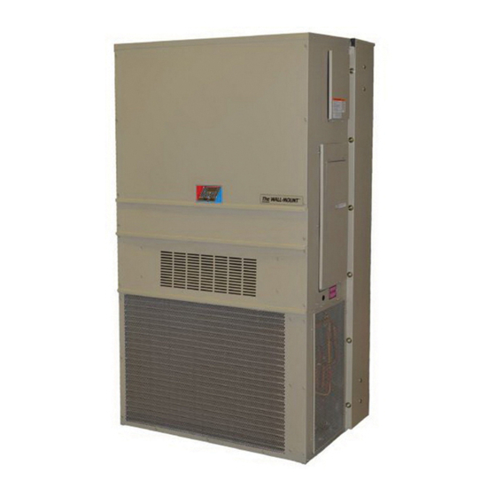
Wall mounted packaged heat pump
Hide thumbs
Also See for C36H1-A:
- Installation instructions manual (25 pages) ,
- Installation instructions manual (25 pages)
Table of Contents
Advertisement
Quick Links
Advertisement
Table of Contents
Troubleshooting

Related Manuals for Bard C36H1-A


Summary of Contents for Bard C36H1-A
- Page 1 INSTALLATION INSTRUCTIONS Wall Mounted Packaged Heat Pump Models: C36H1-A C48H1-A C36H1-B C48H1-B C36H1-C C48H1-C C42H1-A C60H1-A C42H1-B C60H1-B C42H1-C C60H1-C Bard Manufacturing Company, Inc. Manual: 2100-586G Bryan, Ohio 43506 Supersedes: 2100-586F Date: 8-13-21 www.bardhvac.com Page 1 of 25...
-
Page 2: Table Of Contents
CONTENTS General Information ..........4 FIGURES General ............... 4 Figure 1 Fresh Air Damper Assembly....6 Shipping Damage ..........4 Figure 2 Unit Dimensions ........8 Additional Publications ......... 4 Figure 3 Mounting Instructions......9 Duct Work ............6 Figure 4 Electric Heat Clearance ....... 10 Filters .............. - Page 3 Heat Pump Wall Mount Model Nomenclature – MODEL SERIES CONTROL MODULES (See Spec. Sheet S3459) CAPACITY 36 – 3 Ton COIL OPTIONS 42 – 3½ Ton X – Standard Hydrophilic Fin 48 – 4 Ton Indoor Coil & Uncoated 60 – 5 Ton Aluminum Outdoor Coil 1 –...
-
Page 4: General Information
GENERAL INFORMATION General Additional Publications The equipment covered in this manual is to be These publications can help when installing the air installed by trained, experienced service and conditioner. They can usually be found at the local installation technicians. library or purchased directly from the publisher. Be sure to consult the current edition of each standard. - Page 5 ANSI Z535.5 Definitions: WARNING DANGER: Indicate[s] a hazardous situation which, if not avoided, will result in death or serious injury. The signal word “DANGER” is to be limited to the most Electrical shock hazard. extreme situations. DANGER [signs] should not be used for property damage hazards unless personal injury risk Do not operate this equipment without an appropriate to these levels is also involved.
-
Page 6: Duct Work
Any grille that meets with 5/8" louver criteria may the top of the unit down to the unit base. There are be used. It is recommended that Bard Return Air openings in the unit base for the drain hose to pass Grille Kits RG2 through RG5 or RFG2 through RFG5 through. -
Page 7: Installation
INSTALLATION (depending upon wall construction). Be sure to WARNING observe required clearance if combustible wall. Placement 1. On side-by-side installations, maintain a minimum Heavy item hazard. of 20" clearance on right side to allow access to Failure to bolt the unit to the wall could control panel and heat strips and to allow proper result in the unit falling. -
Page 8: Figure 2 Unit Dimensions
TABLE 1 TABLE 2 Clearance Required for Service Access and Minimum Clearances Required Adequate Condenser Airflow to Combustible Materials Left Right Model Supply Air Duct (1st 3') Cabinet Model Side Side C36H C36H C42H C42H 1/4" 0" 36" 36" C48H C48H C60H C60H... -
Page 9: Figure 3 Mounting Instructions
Manual 2100-586G Page 9 of 25... -
Page 10: Figure 4 Electric Heat Clearance
FIGURE 4 Electric Heat Clearance SIDE SECTION VIEW OF SUPPLY AIR DUCT FOR WALL MOUNTED UNIT SHOWING 1/4 INCH CLEARANCE TO COMBUSTIBLE SURFACES. WARNING Fire hazard. Maintain minimum 1/4" clearance between the supply air duct and combustible materials in the first 3' of ducting. Failure to do so could result in fire causing damage, injury or death. -
Page 11: Figure 5 Wall Mounting Instructions
FIGURE 5 Wall Mounting Instructions WALL STRUCTURE SEE FIGURE 3 – MOUNTING INSTRUCTIONS FACTORY SUPPLIED RAIN FLASHING. MOUNT ON UNIT BEFORE INSTALLATION SUPPLY AIR SUPPLY AIR SUPPLY AIR DUCT OPENING OPENING RETURN AIR RETURN AIR RETURN AIR OPENING OPENING OPENING BOTTOM MOUNTING WOOD OR STEEL SIDING BRACKET. -
Page 12: Figure 7 Common Wall Mounting Installations
FIGURE 7 Common Wall Mounting Installations Non-Ducted Installations Ducted Installations Unit is Unit is Ceiling Ceiling sealed to sealed to wall. wall. Supply Air Duct Adjustable Supply Grille Optional Dropped Ceiling Wall Wall Mount Mount Fixed Blade Unit Unit Fixed Blade Return Grille Return Grille Indoor Area Indoor Area... -
Page 13: Wiring - Main Power
Wiring – Main Power Wiring – Low Voltage 230/208V, 1 phase and 3 phase units are equipped Refer to the unit serial plate for wire sizing information with dual primary voltage transformers. All equipment and maximum fuse or circuit breaker size. Each outdoor unit is marked with a “Minimum Circuit leaves the factory wired on 240V tap. -
Page 14: Start Up
All C**H wall-mounted air conditioner series models Topping Off System Charge are supplied with a remote reset for the high and low If a leak has occurred in the system, Bard pressure switch. If tripped, the pressure switch may be Manufacturing recommends reclaiming, evacuating reset by turning the thermostat off then back on again. -
Page 15: Phase Monitor
Sequence of Operation Since there is a 50-50 chance of connecting power in such a way as to cause rotation in the reverse Cooling Stage 1 – Circuit R-Y makes at thermostat direction, verification of proper rotation must be made. pulling in compressor contactor, starting the Verification of proper rotation direction is made by compressor and outdoor motor. -
Page 16: Defrost Cycle
Defrost Cycle There is an initiate defrost jumper (sen jump) on the control that can be used at any outdoor ambient during The defrost cycle is controlled by temperature and time the heating cycle to simulate a 0° coil temperature. on the solid state heat pump control. -
Page 17: Figure 8 Defrost Control Board
FIGURE 8 Defrost Control Board TIME (SEC) LOW PRESSURE BYPASS TIMER SWITCH 120* *(FACTORY SETTING 120 SECONDS) ACCUMULATED DEFROST TIME TIMER (FACTORY SETTING 60 MIN.) MIS-2668 A Manual 2100-586G Page 17 of 25... -
Page 18: Service
SERVICE Solid State Heat Pump Control NOTE: If there was no power to 24 volt transformer, Troubleshooting Procedure the compressor and outdoor fan motor will not start for 5 minutes. This is because of the 1. NOTE: A thorough understanding of the defrost compressor short cycle protection. -
Page 19: Checking Temperature Sensor Outside Unit Circuit
Checking Temperature Sensor Outside 3. Check resistance reading to chart of resistance. Use sensor ambient temperature. (Tolerance of part Unit Circuit is ± 10%.) 1. Disconnect temperature sensor from board and 4. If sensor resistance reads very low, sensor is from outdoor coil. -
Page 20: Fan Blade Setting Dimensions
Fan Blade Setting Dimensions Removal of Fan Shroud Shown in Figure 9 is the correct fan blade setting for 1. Disconnect all power to the unit. proper air delivery across the outdoor coil. Refer to 2. Remove the screws holding both grilles, one on Table 5 for unit specific dimension. -
Page 21: Table 6A Cooling Pressure
TABLE 6A Cooling Pressures COOLING AIR TEMPERATURE ENTERING OUTDOOR COIL °F RETURN AIR MODEL PRESSURE 75°F 80°F 85°F 90°F 95°F 100°F 105°F 110°F 115°F 120°F TEMPERATURE 75° DB LOW SIDE 62° WB HIGH SIDE 80° DB LOW SIDE C36H 67° WB HIGH SIDE 85°... -
Page 22: Table 7 Electrical Specifications
TABLE 7 Electrical Specifications — C**H Series Single Circuit Multiple Circuit Rated Field Model Volts & Max. Circuit Max. Field Minimum Circuit Field Power Power Minimum Exterior Fuse Ground Wire Phase Ampacity Wire Size External Power Ground Circuits Circuit or Ckt. -
Page 23: Table 8 Indoor Blower Performance
TABLE 8 C**H INDOOR BLOWER PERFORMANCE - CFM (0.00" — 0.50" H 0) Rated Cooling Cooling Model Blower Electric & Heat Pump & Heat Pump Only Heat Stage 1 Stage 2 C36H 1100 1100 C42H 1250 1250 C48H 1000... -
Page 24: Troubleshooting Ecm Indoor Blower Motors
Troubleshooting ECM Indoor Blower Motors CAUTION: Disconnect power from unit before removing or replacing connectors, or servicing motor. To avoid electric shock from the motor’s capacitors, disconnect power and wait at least 5 minutes before opening motor. Do’s and Dont’s Symptom Cause/Procedure Don’t... -
Page 25: Figure 10 Control Disassembly
Replacing ECM Control Module Verify that the replacement control is correct for the application. Refer to the manufacturer’s authorized The following steps must be taken to replace the control module replacement list. Using the wrong control will result for the GE variable-speed indoor blower motor: in improper or no blower operation.
Need help?
Do you have a question about the C36H1-A and is the answer not in the manual?
Questions and answers