Contents Getting Other Information and Publications Start Up General ............... 14 Wall Mount General Information Topping Off System Charge ........14 Wall Mount Model Nomenclature ......4 Safety Practices ............14 Shipping Damage ............. 4 Important Installer Note ........... 15 General ..............
GETTING OTHER INFORMATION AND PUBLICATIONS These publications can help you install the air FOR MORE INFORMATION, CONTACT conditioner or heat pump. You can usually find these THESE PUBLISHERS: at your local library or purchase them directly from the publisher. Be sure to consult current edition of each ACCA Air Conditioning Contractors of America standard.
WALL MOUNT GENERAL INFORMATION HEAT PUMP WALL MOUNT MODEL NOMENCLATURE – MODEL REVISIONS CONTROL MODULES NUMBER 0Z - 0KW (See Spec. Sheet S3447) 04 - 4KW CAPACITY | 05 - 5KW 30 - 2½ Ton H - Heat Pump 06 - 6KW COIL OPTIONS VOLTS &...
Any grille that meets with 5/8 inch louver criteria may be CONDENSATE DRAIN used. It is recommended that Bard Return Air Grille Kit A plastic drain hose extends from the drain pan at RG2 through RG5 or RFG2 through RFG5 be installed the top of the unit down to the unit base.
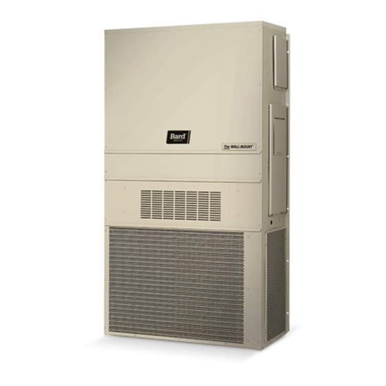
INSTALLATION INSTRUCTIONS WARNING WARNING Failure to bolt the unit to the wall could result Failure to provide the 1/4 inch clearance in the unit falling, causing injury or death! between the supply duct and a combustible Follow all mounting instructions. surface for the first 3 feet of duct can result in fire causing damage, injury or death.
noise and vibration levels, remove the compressor shipping brackets after the unit is in its final operating location. Remove the side grille to gain access to the compressor shipping brackets. The brackets are located on the compressor double isolation base at the front and rear of the compressor.
FIGURE 4 ELECTRIC HEAT CLEARANCE SIDE SECTION VIEW OF SUPPLY AIR DUCT FOR WALL MOUNTED UNIT SHOWING 1/4 INCH CLEARANCE TO COMBUSTIBLE SURFACES. WARNING A minimum of 1/4 inch clearance must be maintained between the supply air duct and combustible materials. This is required for the first 3 feet of ducting.
FIGURE 5 WALL MOUNTING INSTRUCTIONS WALL STRUCTURE SEE FIGURE 3 – MOUNTING INSTRUCTIONS FACTORY SUPPLIED RAIN FLASHING. MOUNT ON UNIT BEFORE INSTALLATION SUPPLY AIR SUPPLY AIR SUPPLY AIR DUCT OPENING OPENING RETURN AIR RETURN AIR RETURN AIR OPENING OPENING OPENING BOTTOM MOUNTING WOOD OR STEEL SIDING BRACKET.
FIGURE 7 COMMON WALL MOUNTING INSTALLATIONS SUPPLY DUCT MAY BE LOCATED IN AN ATTIC OR BELOW CEILING RAFTERS AS SHOWN RAIN RAIN FLASHING RAFTERS FLASHING RAFTERS FINISHED CEILING SURFACE SUPPLY AIR DUCT SUPPLY AIR DUCT FINISHED CEILING SURFACE W/ GRILLE RETURN AIR RETURN AIR OPENING W/ GRILLE...
WIRING – LOW VOLTAGE WIRING WIRING – MAIN POWER 230/208V, 1 phase and 3 phase equipment dual primary Refer to the unit rating plate for wire sizing information voltage transformers. All equipment leaves the factory and maximum fuse or “HACR” type circuit breaker size.
TOPPING OFF SYSTEM CHARGE 8. Store cylinders in a cool area, out of direct sunlight. If a leak has occurred in the system, Bard Manufacturing recommends reclaiming, evacuating 9. Never heat cylinders above 125°F. (see criteria above), and charging to the nameplate 10.
START UP (Continued) IMPORTANT INSTALLER NOTE PHASE MONITOR For improved start up performance wash the indoor coil All units with three phase scroll compressors are with a dish washing detergent. equipped with a 3-phase line monitor to prevent compressor damage due to phase reversal. HIGH &...
SEQUENCE OF OPERATION the factory with the defrost time on the 60 minute pin. If circumstances require a change to another time, remove the COOLING STAGE 1 – Circuit R-Y makes at thermostat wire from the 60-minute terminal and reconnect to the desired pulling in compressor contactor, starting the compressor and terminal.
TROUBLESHOOTING SOLID STATE HEAT PUMP CONTROL NOTE: If there was no power to 24 volt transformer, TROUBLESHOOTING PROCEDURE the compressor and outdoor fan motor will 1. NOTE: A thorough understanding of the defrost not start for 5 minutes. This is because of cycle sequence is essential.
CHECKING TEMPERATURE SENSOR 3. Check resistance reading to chart of resistance. Use OUTSIDE UNIT CIRCUIT sensor ambient temperature. (Tolerance of part is ± 10%.) 1. Disconnect temperature sensor from board and 4. If sensor resistance reads very low, then sensor is from outdoor coil.
TROUBLESHOOTING FAN BLADE SETTING DIMENSIONS REMOVAL OF FAN SHROUD Shown in Figure 9 is the correct fan blade setting for 1. Disconnect all power to the unit. proper air delivery across the outdoor coil. Refer to 2. Remove the screws holding both grilles, one on Table 4 for unit specific dimension.
TABLE 5A COOLING PRESSURE TABLE Air Temperature Entering Outdoor Coil °F Return Air Model Pressure Temperature 75 deg. DB Low SIde 62 deg. WB High Side 80 deg. DB Low SIde T30S 67 deg. WB High Side 85 deg. DB Low SIde 72 deg.
TABLE 6B Electrical Specifications — T**S Series Dehumidification Single Circuit Multiple Circuit Maximum Circuit No. of Maximum Minimum Circuit Field Power Wire Exterior Fuse or Ground WIre Size Minimum External Field Rated Volts, HZ Field Ampacity Size Ground Models Circuit Breaker ...
TROUBLESHOOTING GE ECM MOTORS ™ Symptom Cause/Procedure CAUTION: • Noisy blower or cabinet • Check for loose blower housing, panels, etc. Disconnect power from unit before removing or replacing • High static creating high blower speed? connectors, or servicing motor. To avoid electric shock from - Check for air whistling through seams in the motor’s capacitors, disconnect power and wait at least 5 ducts, cabinets or panels...
TROUBLESHOOTING GE ECM ™ MOTORS CONT’D. TROUBLESHOOTING GE ECM MOTORS CONT’D. ™ 8b. IF REPLACING AN ECM 2.3 CONTROL WITH AN ECM 2.3 Replacing ECM Control Module CONTROL, the plastic tab and shorter through-bolts are not needed. The To replace the control module for the GE variable-speed indoor blower Replacing ECM Control Module 8b.