Table of Contents
Advertisement
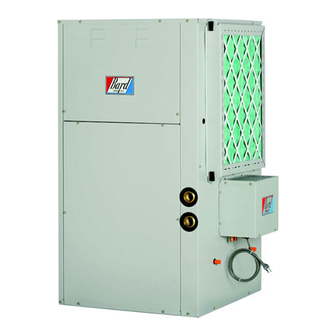
INSTALLATION
INSTRUCTIONS
Ground Water Temperatures 45° - 75°
WATER SOURCE
HEAT PUMPS
Models:
Earth Loop Fluid
Temperatures 25° - 110°
Bard Manufacturing Company, Inc.
Bryan, Ohio 43506
Since 1914...Moving ahead, just as planned.
GV27S1-A, GV38S1-A
GV51S1-A, GV61S1-A
GV71S1-A
MIS-2615
Manual:
Supersedes: 2100-510D
File:
Date:
2100-510E
Volume I, Tab 8
08-04-09
Manual
2100-510E
Page
1 of 38
Advertisement
Table of Contents
Troubleshooting

Related Manuals for Bard GV27S1-A


Summary of Contents for Bard GV27S1-A
-
Page 1: Installation Instructions
Models: GV51S1-A, GV61S1-A GV71S1-A MIS-2615 Earth Loop Fluid Temperatures 25° - 110° Ground Water Temperatures 45° - 75° Bard Manufacturing Company, Inc. Manual: 2100-510E Bryan, Ohio 43506 Supersedes: 2100-510D File: Volume I, Tab 8 Since 1914...Moving ahead, just as planned. -
Page 2: Table Of Contents
CONTENTS Getting Other Informations and Publications ..3 Water Corrosion ..........21 & 22 Remedies of Water Problems ........ 22 General Information Lake and/or Pond Installations ...... 22 & 23 Water Source Nomenclature ........4 Sequence of Operation Heater Package Nomenclature ....... 8 Blower .............. -
Page 3: Getting Other Informations And Publications
GETTING OTHER INFORMATION AND PUBLICATIONS These publications can help you install the air FOR MORE INFORMATION, CONTACT conditioner or heat pump. You can usually find these at THESE PUBLISHERS: your local library or purchase them directly from the publisher. Be sure to consult current edition of each ACCA Air Conditioning Contractors of America standard. -
Page 4: General Information Water Source Nomenclature
WATER SOURCE PRODUCT LINE NOMENCLATURE Revision Level C = Copper Water Coil Ground N = Cupronickel Source Electrical 230/208V 1-Phase Vertical Step Capacity 38 = Nominal heating capacity in thousands @ 50° water - Full Load Nominal cooling capacity in thousands @ 77° brine - Full Load TABLE 1 INDOOR BLOWER PERFORMANCE (RATED CFM) 1 f r i... -
Page 5: Table 2 Flow Rates For Various Fluids
TABLE 2 FLOW RATES FOR VARIOUS FLUIDS 1 Rated Flow TABLE 3 SPECIFICATIONS a t l i n i t i u y t i . t k . r k s t l . t k +75°C copper wire ++ HACR type circuit breaker * C - for copper / N for Cupro-Nickel water coil 1 Heat pump only. -
Page 6: Table 4 Water Coil Pressure Drop
TABLE 4 WATER COIL PRESSURE DROP Manual 2100-510E Page 6 of 38... -
Page 7: Figure 1 Unit Dimensions
Manual 2100-510E Page 7 of 38... -
Page 8: Heater Package Nomenclature
HEATER PACKAGE NOMENCLATURE Circuit Breaker Nominal KW 240/208-1-60 Modification Code 3 = 3 Ton 5 = 5 Ton Electric Ground Source Vertical Heater TABLE 5 ELECTRICAL SPECIFICATIONS & & + Based on 75F copper wire. All wiring must conform to National Electrical Code (latest edition) and all local codes. Manual 2100-510E Page 8 of 38... -
Page 9: Application And Location
APPLICATION AND LOCATION GENERAL Unit casing suitable for 0 inch clearance with 1-inch duct clearance for at least the first 3 feet of duct. These units Units are shipped completely assembled and internally are not approved for outdoor installation and therefore wired, requiring only duct connections, thermostat wiring, must be installed inside the structure being conditioned. -
Page 10: Figure 2 Field-Conversion To Left Hand Return
FIGURE 2 FIELD-CONVERSION TO LEFT HAND RETURN Panel removed for clarity. Does not need removed to change control panel location. MIS-2617 1. Remove control panel fill plate. 2. Remove two screws securing control panel to unit. 3. Pass control panel through blower section rotating 180°. 4. -
Page 11: Filters
FILTER CONDENSATE DRAIN This unit must not be operated without a filter. It comes Drain lines must be installed according to local plumbing equipped with 2" disposable filters, which should be codes. It is not recommended that any condensate drain checked often and replaced if dirty. -
Page 12: Figure 3 Filter Rack Configuration
Manual 2100-510E Page 12 of 38... -
Page 13: Figure 4 Piping Access
FIGURE 4 CONDENSATE DRAIN & PIPING ACCESS TO UNIT Water in connection MIS-2619 Water out connection Condensate drain access (4) locations Desuperheater Pump module connections 1/2" I.D. copper stub Manual 2100-510E Page 13 of 38... -
Page 14: Wiring Instructions
WIRING INSTRUCTIONS GENERAL TABLE 6 CONTROL CIRCUIT WIRING All wiring must be installed in accordance with the National Electrical Code and local codes. In Canada, all wiring must be installed in accordance with the Canadian Electrical Code and in accordance with the regulations of the authorities having jurisdiction. -
Page 15: Figure 5 Thermostat Wiring
(See notes 1 & 2 below) Unit 24V terminal strip Bard part # 8603-030 Motorized valve with end switch (part of Bard GVGWK-1 Ground Water Kit) Standard two-wire solenoid valve GROUND WATER APPLICATIONS (when installed with recommended motorized valve with end switch) 8403-060 (1120-445) -
Page 16: Ground Loop (Earth Coupled Water Loop Applications) Note
The and circulator selection will eliminate this problem. design eliminates most causes of system failure. Bard supplies a work sheet to simplify heat loss The heat pump itself is rarely the cause. Most problems calculations and circulator selection. Refer to occur because designers and installers forget that a “Circulating Pump Worksheet”... -
Page 17: Start Up Procedure For Ground Loop System
START UP PROCEDURE FOR GROUND recheck the selection of the loop pump module model LOOP SYSTEM for sufficient capacity. If the module selection is correct, there is probably trapped air or a restriction in 1. Be sure main power to the unit is OFF at disconnect. the piping circuit. -
Page 18: Figure 7 Temperature & Pressure Measurement
FIGURE 7 Thermometer Dial face pressure guage with guage adaptor Retaining cap, hand tighten only Pete's test plug Test plug cap Barbed 90° adapter MIS-2622 FIGURE 8 PERFORMANCE MODEL DORFC-1 FLOW CENTER Flow (GPM) FIGURE 9 PERFORMANCE MODEL DORFC-2 FLOW CENTER Flow (GPM) Manual 2100-510E Page... -
Page 19: Ground Water (Well System Applications)
GROUND WATER (WELL SYSTEM APPLICATIONS) NOTE: Strainer (8) installed upstream of water coil inlet to collect foreign material which would clog the flow valve orifice. Unit shipped from factory with 60 PSIG low pressure switch wired into control circuit for open loop The figure shows the use of shutoff valves (4) and (5), on applications. -
Page 20: Figure 10 Water Connection Components
The pressure requirements put on the pump are directly the piping is not undersized, which would create too much affected by the diameter of pipe being used, as well as, by pressure due to friction loss. High pressure losses due to the water flow rate through the pipe. -
Page 21: Start Up Procedure For Ground Water System
SYSTEM START UP PROCEDURE FOR WATER CORROSION GROUND WATER APPLICATIONS Two concerns will immediately come to light when 1. Be sure main power to the unit is OFF at disconnect. considering a water source heat pump, whether for ground water or for a ground loop application: Will there be 2. -
Page 22: Figure 11 Cleaning Water Coil
4. Scale Formation. Of all the water problems, the LAKE AND POND INSTALLATIONS formation of scale by ground water is by far the most Lakes and ponds can provide a low cost source of water for common. Usually this scale is due to the formation of heating and cooling with a ground water heat pump. -
Page 23: Figure 12 Lake Or Pond Installation
C. If possible, use a submersible pump suspended in the J. The drain line should be installed with a slope of 2 dry well casing. Jet pumps and other types of suction inches per 10 feet of run to provide complete drainage pumps normally consume more electrical energy than of the line when the ground water heat pump is not similarly sized submersible pumps. -
Page 24: Sequence Of Operation
SEQUENCE OF OPERATION PART LOAD HEATING (No Electric Heat) BLOWER When thermostat system switch is placed in HEAT, the Blower functions are all automatic through the thermostat reversing valve solenoid is no longer energized. On a call control. (See Table 1 for the specific airflows on each for part load heating, the thermostat completes a circuit speed.) Motor control inputs are all 24 VAC with line from “R”... -
Page 25: Compressor Control Module
SEQUENCE OF OPERATION PRESSURE SERVICE PORTS COMPRESSOR CONTROL MODULE High and low pressure service ports are installed on all The compressor control module is an anti-short cycle/ units so that the system operating pressures can be lockout timer with high and low pressure switch observed. -
Page 26: Figure 13 Component Location
FIGURE 13 COMPONENT LOCATION LOW PRESSURE SWITCHES EXPANSION VALVE SUCTION SERVICE PORT DISCHARGE SERVICE PORT DESUPERHEAT COIL HIGH VOLTAGE IN FLOW CENTER POWER COMPRESSOR WATER COIL HIGH PRESSURE SWITCH REVERSING VALVE MIS-2625 FIGURE 14 CONTROL PANEL E. HEAT TERMINAL TERMINAL GROUND CIRCUIT TRANSFORMER... -
Page 27: Figure 15 Refrigerant Flow Diagrams
FIGURE 15 Manual 2100-510E Page 27 of 38... -
Page 28: Figure 16A Pressure Tables
Manual 2100-510E Page 28 of 38... -
Page 29: Figure 16B Pressure Tables
FIGURE 16B PRESSURE TABLES — F ° F ° F ° F ° F ° F ° F ° F ° F ° F ° F ° F ° F ° F ° F ° F ° F ° F ° °... -
Page 30: Quick Reference Troubleshooting Chart
Manual 2100-510E Page 30 of 38... -
Page 31: Service
SERVICE SERVICE HINTS COMPRESSOR SOLENOID 1. Caution owner to maintain clean air filters at all times. (See Sequence of Operation on Pages 24 & 25 for function.) Also, not to needlessly close off supply and return air A nominal 24-volt direct current coil activates the internal registers. -
Page 32: Figure 17 Motor Connections
TROUBLESHOOTING GE X13-SERIES ECM MOTORS If the Motor is Running e. If the motor does not shut off at the end of the cycle, wait for any programmed delays to time out (no more 1. It is normal for the motor to rock back and forth on start than 90 seconds). -
Page 33: Figure 18 Motor Connections
TROUBLESHOOTING GE X13-SERIES ECM MOTORS CONT’D. 2. Initiate a demand from the thermostat and check the Model X13 Communication Diagnostics voltage between the common and the appropriate motor The X13 motor is communicated through 24 VAC low voltage terminal (1-5). ("G" input is typically on terminal #1, but (Thermostat Control Circuit Wiring). -
Page 34: Figure 19 Typical Pump Kit Connection
ACCESSORIES ADD-ON GVDM-26 PUMP MODULE KIT INSTALLATION NOTE: This section applies only if a GVDM-26 Pump 1. Follow all local, state, and national codes applicable to Module is added. Refer to GVDM-26 instructions for the installation of the pump module kit. complete installation details. -
Page 35: Ground Source Heat Pump Performance Report
GROUND SOURCE HEAT PUMP PERFORMANCE REPORT This performance check report should be filled out by installer and retained with unit. DATE TAKEN BY: UNIT: Mfgr Model No. THERMOSTAT: Mfgr Model No. Person Reporting Company Reporting Installed By Date Installed User’s (Owner’s) Name Address Unit Location WATER SYSTEM INFORMATION... - Page 36 THE FOLLOWING INFORMATION IS NEEDED TO CHECK PERFORMANCE OF UNIT. FLUID SIDE DATA Cooling ** Heating Entering fluid temperature Leaving fluid temperature Entering fluid pressure PSIG Leaving fluid pressure PSIG Pressure drop through coil PSIG Gallons per minute through the water coil Liquid or discharge line pressure PSIG Suction line pressure...
-
Page 37: Wiring Diagrams
Manual 2100-510E Page 37 of 38... -
Page 38: Power Source
Line 1 Line 2 230/208-60-1 Power Source Circuit Circuit Terminal Terminal Breaker Breaker Block Block Compressor Capacitor 4 Pin Plug for Indoor Blower Motor Transformer 24VAC High Pressure Control Compressor Emergency Contactor Heat Relay Comp. Low Pressure Control Control Module Blower Control 3 Pin Heater...
Need help?
Do you have a question about the GV27S1-A and is the answer not in the manual?
Questions and answers