Table of Contents
Advertisement
Quick Links
LIGHT COMMERCIAL
HYPER SPLIT AIR CONDITIONER
WITH HEAT PUMP
INSTALLATION MANUAL
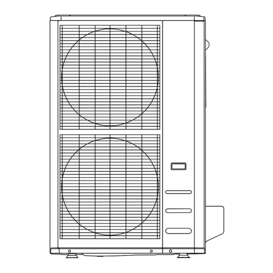
OUTDOOR UNIT
IMPORTANT NOTE:
•
Read this manual carefully before installing or operating your new air conditioning unit.
Make sure to save this manual for future reference.
•
This manual only describes the installation of the indoor unit. When installing the outdoor
unit, refer to the installation manual of the outdoor unit.
CH-HYP36CLUO
CH-HYP48CLUO
Advertisement
Table of Contents

Related Manuals for Cooper & Hunter CH-HYP36CLUO


Summary of Contents for Cooper & Hunter CH-HYP36CLUO
- Page 1 LIGHT COMMERCIAL HYPER SPLIT AIR CONDITIONER WITH HEAT PUMP INSTALLATION MANUAL OUTDOOR UNIT CH-HYP36CLUO CH-HYP48CLUO IMPORTANT NOTE: • Read this manual carefully before installing or operating your new air conditioning unit. Make sure to save this manual for future reference.
-
Page 2: Table Of Contents
Table of Contents Installation Manual 1. Accessories ...........................3 2. Safety Precautions ........................4 3. Installation Summary ........................5 4. Unit Parts ............................6 5. Indoor Unit Installation .......................7 1. Select installation location ..........................7 2. Hang indoor unit ..............................9 3. Drill wall hole for connective piping ......................11 4. -
Page 3: Accessories
Accessories The air conditioning system comes with the following accessories. Use all of the installation parts and accessories to install the air conditioner. Improper installation may result in water leakage, electrical shock and fire, or cause the equipment to fail. The items not included with the air conditioner must be purchased separately. -
Page 4: Safety Precautions
Safety Precautions Read safety precautions before installation Incorrect installation due to ignoring instructions can cause serious damage or injury. The seriousness of potential damage or injuries is classified as either a WARNING or CAUTION. WARNING Failure to observe a warning may result in death. The appliance must be installed in accordance with national regulations. -
Page 5: Installation Summary
Installation Summary Install the indoor unit Install the drainpipe Install the outdoor unit Evacuate the refrigeration Connect the wires Connect the refrigerant system pipes Perform a test run Page 5... -
Page 6: Unit Parts
Unit Parts NOTE: The installation must be performed in accordance with local and national standards. The installation may be slightly different in different areas. 1. Air flow louver (at air outlet) 2. Air inlet (with air filter in it) 3. Installation part 4. -
Page 7: Indoor Unit Installation
Indoor Unit Installation INSTALLATION INSTRUCTIONS – INDOOR UNIT NOTE: Panel installation should be performed after piping and wiring have been completed. Step 1: Select installation location Before installing the indoor unit, you must choose an appropriate location. The following are standards that will help you choose an appropriate location for the unit. - Page 8 Refrigerant pipe connection (D. gas side) Drain point Refrigerant pipe connection (E. Liquid side) Hook Indoor parts installation size Length of A Length of B Length of C Length of D Length of E MODEL(Btu/h) (in/mm) (in/mm) in/mm) (in/mm) (in/mm) 18k~24k 42/1068 26.6 /675...
-
Page 9: Hang Indoor Unit
Other features Step 2: Hang indoor unit CAUTION Wood The unit body must be completely aligned with Place the wood mounting across the roof beam, the hole. Ensure that the unit and the hole are then install the hanging screw bolts. the same size before moving on. - Page 10 8. Remove the side board and the grille. How to install the conduit installation plate (if supplied) 1. Fix the sheath connector (not supply) on the wire hole of the conduit installation plate. 2. Fix the the conduit installation plate on the chassis of the unit.
-
Page 11: Drill Wall Hole For Connective Piping
Step 3: Drill wall hole for connective Indoor Drainpipe Installation piping Install the drainpipe as illustrated in the following Figure. 1. Determine the location of the wall hole based on the location of the outdoor unit. 2. Using a 2.5in/65mm or 3.54in/90mm (depending on models) core drill, drill a hole in the wall. -
Page 12: Outdoor Unit Installation
Outdoor Unit Installation DO NOT install unit in the following locations: Unit must be installed in accordance with local codes and regulations, which may vary from Near an obstacle that will block air inlets and region to region. outlets Near a public street, crowded areas, or where noise from the unit will disturb others Near animals or plants that will be harmed by hot air discharge... -
Page 13: Install Drain Joint
Step 2: Install drain joint (Heat pump Step 3: Anchor outdoor unit unit only) The outdoor unit can be anchored to the ground or to a wall-mounted bracket with bolt Before bolting the outdoor unit in place, you (M10). Prepare the installation base of the unit must install the drain joint at the bottom of the according to the dimensions below. - Page 14 (unit: in/mm) Mounting Dimensions, in/mm Outdoor Unit Dimensions, in/mm W x D x H Distance A Distance B 37.24x16.14x31.89/946x410x810 26.5/673 15.87/403 37.48x16.34x52.48/952x415x1333 24.96 /634 15.9/404 Rows of series installation The relations between H, A and L are as follows. L≤H 9.8in/25 cm or more L≤H 1/2H<L≤H...
-
Page 15: Refrigerant Piping Connection
Refrigerant Piping Connection When connecting refrigerant piping, do not let substances or gasses other than the specified refrigerant enter the unit. The presence of other gasses or substances will lower the unit’s capacity, and can cause abnormally high pressure in the refrigeration cycle. This can cause explosion and injury. -
Page 16: Connection Instructions -Refrigerant Piping
Step 1: Cut pipes CAUTION When preparing refrigerant pipes, take extra care to cut and flare them properly. This will If the outdoor unit is installed higher than the ensure efficient operation and minimize the indoor unit: need for future maintenance. •... -
Page 17: Connect Pipes
Step 4: Connect pipes 2. Sheath the pipe with insulating material. 3. Place flare nuts on both ends of pipe. Make Connect the copper pipes to the indoor unit sure they are facing in the right direction, first, then connect it to the outdoor unit. You because you can’t put them on or change should first connect the low-pressure pipe, then their direction after flaring. - Page 18 NOTE ON MINIMUM BEND RADIUS 6. Thread this pipeline through the wall and connect it to the outdoor unit. Carefully bend the tubing in the middle 7. Insulate all the piping, including the valves according to the diagram below. DO NOT of the outdoor unit.
-
Page 19: Wiring
Wiring 11. If the unit has an auxiliary electric heater, it WARNING must be installed at least 40in/1m away from any combustible materials. BEFORE PERFORMING ANY 12. To avoid getting an electric shock, always ELECTRICAL WORK, READ wait 10 minutes or more before you touch THESE REGULATIONS the electrical components after the power supply has been turned off. -
Page 20: Outdoor Uint Wiring
Outdoor Unit Wiring WARNING BEFORE PERFORMING ANY ELECTRICAL OR WIRING WORK, TURN OFF THE MAIN POWER TO THE SYSTEM. 1. Prepare the cable for connection a. You must first choose the right cable size. Be sure to use H07RN-F cables. Minimum Cross-Sectional Area of Power and Signal Cables North America Rated Current... -
Page 21: Indoor Uint Wiring
Magnetic ring (if supplied and packed with the 3. Connect the u-lugs to the terminals, match the wire colors/labels with the labels on the accessories) terminal block, and firmly screw the u-lug of each wire to its corresponding terminal. 4. Clamp down the cable with designated cable clamp. - Page 22 Power Specifications NOTE: Electric auxiliary heating type circuit breaker/fuse need to add more than 10 A. Indoor Power Supply Specifications MODEL(Btu/h) ≤18k ~24k ~36k ~48k ~60k PHASE 1 Phase 1 Phase 1 Phase 1 Phase 1 Phase POWER VOLT 208-240V 208-240V 208-240V 208-240V...
-
Page 23: Air Evacuation
Air Evacuation Preparations and Precautions 6. Close the Low Pressure side of the manifold gauge, and turn on the vacuum pump. Air and foreign matter in the refrigerant circuit 7. Wait for 5 minutes, then check that there has can cause abnormal rises in pressure, which been no change in system pressure. -
Page 24: Indoor Uint Wiring
Indoor Unit Wiring Some systems require additional charging depending on pipe lengths. The standard pipe length varies according to local regulations. For example, in North America, the standard pipe length is 25ft/7.5m. In other areas, the standard pipe length is 16ft /5m. The refrigerant should be charged from the service port on the outdoor unit’s low pressure valve. -
Page 25: Test Run
Test Run Before Test Run e. Ensure the manual buttons on the indoor unit works properly. A test run must be performed after the entire f. Check to see that the drainage system is system has been completely installed. Confirm unimpeded and draining smoothly.
Need help?
Do you have a question about the CH-HYP36CLUO and is the answer not in the manual?
Questions and answers