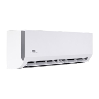
Cooper & Hunter CH-18MES-230VO Installation Manual

Cooper & Hunter CH-18MES-230VO Installation Manual

Multi-zone mini split ac with heat pump

Advertisement

Installation Manual
MULTI-ZONE MINI SPLIT AC WITH HEAT PUMP
CH-18MES-230VO
CH-28MES-230VO
CH-36MES-230VO
CH-48MES-230VO
CH-55MES-230VO
CH-HPR19M-230VO
CH-HPR28M-230VO
CH-HPR36M-230VO
CH-HPR48M-230VO
CH-HPR55M-230VO
IMPORTANT NOTE:
Read this manual carefully before installing
unit. Make sure to save this manual for
future reference.

Advertisement

Table of Contents
loading
Need help?

Need help?

Do you have a question about the CH-18MES-230VO and is the answer not in the manual?

Questions and answers

JL gilbert
January 31, 2025

Where is a wiring diagram for this unit

1 comments:
Mr. Anderson
February 10, 2025

The wiring diagram for the Cooper & Hunter CH-18MES-230VO unit can be found in the installation manual under the "Wiring" section, specifically in the "Wiring Figure" subsection.

This answer is automatically generated

Subscribe to Our Youtube Channel

Summary of Contents for Cooper & Hunter CH-18MES-230VO

  • Page 1 Installation Manual MULTI-ZONE MINI SPLIT AC WITH HEAT PUMP CH-18MES-230VO CH-28MES-230VO CH-36MES-230VO CH-48MES-230VO CH-55MES-230VO CH-HPR19M-230VO CH-HPR28M-230VO CH-HPR36M-230VO CH-HPR48M-230VO CH-HPR55M-230VO IMPORTANT NOTE: Read this manual carefully before installing unit. Make sure to save this manual for future reference.
  • Page 2 Installation Manual Accessories Installation Summary Installation Diagram Specifications Outdoor Unit Installation 2. Install drain joint 3. Anchor outdoor unit Refrigerant Piping Connection 1. Cut pipe 2. Remove burrs 3. Flare pipe ends 4. Connect pipes Wiring 1. Outdoor Uint Wiring 2.
  • Page 3: Optional Accessories

    Accessories r. Impr be purchased separately. Q‘ty(pc) Shape Name of Accessories Shape Name of Accessories Q‘ty(pc) Drain joint Manual (some models) Installation plate Seal ring (some models) (some models) Magnetic ring (Hitch Plastic expansion (depending it on the connective sheath (some models) on models) Varies cable between indoor...
  • Page 4: Installation Summary

    Installation Summary INSTALLATION ORDER (L1) (L2) Install the outdoor unit Connect the refrigerant pipes Connect the wires Evacuate the refrigeration Perform a test run system Page 4...
  • Page 5: Installation Diagram

    Installation Diagram Installation Diagram Mounting screw More than ST3.9 25-C-H 5.9” (15cm) More than More than Air-break Installation plate 4.7” (12cm) 4.7” (12cm) More than Clip anchor 4.7” (12cm) Remote controller holder Drainage Pipe 5 4 3 More than 11.8” (30cm) More than 4.7”...
  • Page 6: Specifications

    Specifications Number of units that can be used Connected units together 3 min or more voltage drop during start interval unbalance Unit: ft/m. 1 drive 2 1 drive 3 1 drive 4 NOTE: Outdoor unit Indoor unit Indoor unit Indoor unit Page 6...
  • Page 7: Special Considerations For Extreme Weather

    Outdoor Unit Installation install unit in the following locations: DO NOT and outlets 24in (60cm) above Near a public street, cr reas, or re noise fr by hot air discharge Near any sour amounts of dust of salty air SPECIAL CONSIDERATIONS FOR EXTREME WEATHER If the unit is exposed to heavy wind: Installation Instructions –...
  • Page 8: Unit Mounting Dimensions

    Step 2: Install drain joint Step 3: Anchor outdoor unit (Heat pump unit only) The outdoor unit can be anchored to the repar unit according to the dimensions belo . joints depending on the type of outdoor unit. UNIT MOUNTING DIMENSIONS If the drain joint comes with a rubber seal (see Fig.
  • Page 9 (unit: inch/mm) Notes On Drilling Hole In Wall Outdoor Unit Dimensions Mounting Dimensions W x H x D Distance A Distance B connect the indoor and outdoor units. re drill, drill a hole 13.1 (333) NOTE: 14.4 (344) res, plumbing, and other 24.96 (634) This protects the edges of the hole and 24.96 (634)
  • Page 10: Connection Instructions - Refrigerant Piping

    Refrigerant Piping Connection NOTE: For quick-connect models, please DO NOT DEFORM PIPE refer to the internal machine manual for the WHILE CUTTING reful not to damage, dent, or deform reduce do not refrigerant piping, Step 2: Remove burrs. refrigerant enter the unit. The presence of other ’s capacity, and can cause abnormally high pressure in the removed.
  • Page 11 re form on the end of the pipe. The Indoor unit tubing Pipe Flare nut form. Flare form 3. T by hand. 4. Using a spanner, grip the nut on the unit tubing. Pipe rque re nut according to the torque values in above table. red.
  • Page 12 Thread this pipeline thr NOTE ON MINIMUM BEND RADIUS connect it to the outdoor unit. Carefully bend the tubing in the middle 8. Insulate all the piping, including the valves according to the diagram belo . DO NOT of the outdoor unit. bend the tubing mor re than 9.
  • Page 13 Wiring BEFORE PERFORMING ANY Make sure that you do not cross your ELECTRICAL WORK, READ THESE REGULATIONS interference. The unit must be connected to the installed by a licensed electrician. must have a impedance of 32 ohms. No other equipment should be accor located on the panels of the indoor and outdoor res before...
  • Page 14: Choose The Right Cable Size

    1. Prepar a. Y (purchased seperately) NOTE: In North America, choose the cable type according to the local electrical codes Indoor unit Outdoor unit (purchased seperately) (purchased seperately) (purchased seperately) Indoor unit CHOOSE THE RIGHT CABLE SIZE Outdoor unit rent of the unit. The rent is indicated on the nameplate (purchased seperately) located on the side panel of the unit.
  • Page 15: Wiring Figure

    Remove the electric cover of the outdoor unit. If there is no cover on the outdoor unit, take Cover re to its corresponding terminal. rom any electrical or metal parts. 6. Reinstall the cover of the electric contr Harmonic declaration public system.
  • Page 16 NOTE: NOTE: One-two models: Model C Model D Model A N L( 1) L(A) N(A) S(A) N L( 1) N(A) S(A) L(A) SUPPLY SUPPLY Model E Model F Model G S(A) N(A) L(A) S(2) S(A) N(A) L(A) S(2) S(A) N(A) L(A) S(2) S(1)
  • Page 17 N L( 1) L(A) N(A) S(A) N L( 1) L(A) N(A) S(A) TO A TO A SUPPLY SUPPLY Model M Model N Model O Model P Model Q Model R L1 L2 L1 L2 2(A) 3(A) 1(A) L1(A) L2(A) S(A) POWER POWER TO A...
  • Page 18 One-three models: Model A Model C Model D Model E Model F TO A TO C TO B SUPPLY Model G Model I 1(L) 2(N) 3(S) 1(L) 2(N) 3(S) 1(L) 2(N) 3(S) To indoor To indoor To indoor unit A unit C Model J Page 19...
  • Page 19 One-four models: Model A 1(L) 2(N) 3(S) 1(L) 2(N) 3(S) 1(L) 2(N) 3(S) 1(L) 2(N) 3(S) Model D Model C TO A TO B TO A TO B SUPPLY Model E Model F Model G Page 20...
  • Page 20 Model J Model I Model L Mode K L(C) N(C) S(C) L(D) N(D) S(D) To indoor To indoor To indoor To indoor unit C unit D unit A Model M Page 21...
  • Page 21 One-five models: 1(L) 2(N) 3(S) 1(L) 2(N) 3(S) 1(L) 2(N) 3(S) 1(L) 2(N) 3(S) 1(L) 2(N) 3(S) Model A Model C Model D Model F Model E Model G Page 22...
  • Page 22 Model J Model I Model K CAUTION • the circuit diagram posted on the inside of the control cover. • • marked on the name plate. • • • 0.11in ( NOTE: the your equipment . ( )or similar) . Page 23...
  • Page 23: Air Evacuation

    Air Evacuation NOTE: If there is no change in system pressure, Preparations and Precautions unscr rom the packed valve (high Air and for refrigerant circuit can pressure valve). If there is a change in system pressure, there may be a gas leak. cause abnormal rises in pressur r, r y, and cause...
  • Page 24: Note On Adding Refrigerant

    Note On Adding Refrigerant CAUTION • DO NOT refrigerant or overcharge the system. • re that the • appropriate refrigerant is used. • system. DO NOT refrigerants types. • • ADDITIONAL REFRIGERANT PER PIPE LENGTH Connective Pipe Air Purging Additional Refrigerant Length(m) Method acuum Pump...
  • Page 25: Safety And Leakage Check

    Safety And Leakage Check Electrical safety check Gas leak check neutral detergent on the indoor unit 1. Insulated resistance The insulated resistance must be more than 2MΩ. 2. Leak detector Use the leak detector to check for leakage. and using the grounding resistance tester. Make sure the grounding resistance is less NOTE: than 4Ω.
  • Page 26 Test Run f. Check to see that the drainage system is Before Test Run unimpeded and draining smoothly. g. Ensure ther For the Outdoor Unit a) The indoor and outdoor units are properly a. Check to see if the r installed.
  • Page 28 The design and specifications are subject to change without prior notice for product improvement. Consult with the sales agency or manufacturer for details. Any updates to the manual will be uploaded to the service website, please check for the latest version.

Table of Contents

Save PDF