
Related Manuals for Yeswelder MIG-205DS


Summary of Contents for Yeswelder MIG-205DS
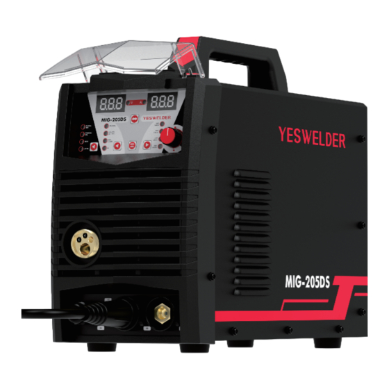
- Page 1 MIG-205DS IGBT INVERTER MULTI-PROCESS WELDER (MIG, MAG, FLUX-CORED, STICK, LIFT TIG) Aug., 2023 OPERATOR’S MANUAL Copyright © YesWelder...
-
Page 3: Table Of Contents
TABLE OF CONTENTS ············································································································································· SAFETY INSTALLATION ··································································································································0 ····················································································································0 Technical Specifications ···························································································································0 Safety Precautions ···········································································································································0 Location ··········································································································································0 Stacking ··············································································································································0 Tilting ······················································································································0 Included Components ACCESSORIES································································································································06 ····································································································································0 DESCRIPTION ·········································································································0 Safety and Product Description Controls and Settings ·······················································································································0 ······································································································· Installing the MIG Gun Assembly ·····························································································... -
Page 4: Safety
SAFETY DEPENDS ON YOU If you develop unusual symptoms, see your supervisor. Per- YESWELDER arc welding and cutting equipment are designed haps the welding atmosphere and ventilation system should be and built with safety. However, your overall safety can be in- checked. - Page 5 SAFETY If fuel is spilled, wipe it up and do not start engine until fumes have been eliminated. WARNINGS 1.d. Keep all equipment safety guards, covers and devices in position and in good repair. Keep hands, hair, clothing and tools away from V- belts, gears, fans and all other moving CALIFORNIA PROPOSITION 65 WARNINGS parts when starting, operating or repair-...
- Page 6 SAFETY ELECTRIC SHOCK ARC RAYS CAN BURN. CAN KILL. 3.a. The electrode and work (or ground) cir- 4.a. Use a shield with the proper filter and cover plates to pro- cuits are electrically “hot” when the tect your eyes from sparks and the rays of the arc when welder is on.
- Page 7 SAFETY CYLINDER MAY EXPLODE IF WELDING AND CUTTING DAMAGED. SPARKS CAN CAUSE FIRE OR EXPLOSION. 7.a. Use only compressed gas cylinders con- taining the correct shielding gas for the process used and properly operating reg- ulators designed for the gas and pres- 6.a.
-
Page 8: Installation
INSTALLATION TECHNICAL SPECIFICATIONS: MIG-205DS Read entire installation section before you starting in- stallation. INPUT-SINGLE PHASE ONLY INSTALLATION Standard Voltage/Frequency Input Current =34A, I1 =26.3A 220V±10% 50/60Hz =43A, I1 =33.2A 110V±10% 50/60Hz WARNIG RATED OUTPUT-DC ONLY Volts at Rated ELECTRIC SHOCK can kill. Voltage Duty Cycle Current... -
Page 9: Accessories
ACCESSORIES 1. Welder 6. U Knurl Groove Drive 2. Work Clamp Roller: .035" & .045" 3. Electrode Stringer 7. 220V~110V Adapter 4. V Knurl Groove 8. MIG Gun Drive Roller: .023"/.0 9. Graphene Feeding Liner 30" (.030" & .035" on 10. -
Page 10: Description
DESCRIPTION SAFETY PRECAUTIONS PRODUCT DESCRIPTION (PRODUCT CAPABILITIES) Read entire operation section before operating This small portable wire feed welder is capable of MIG(GMAW/ the WIRE FEEDER WELDER. flux-cored (FCAW) welding on steel, mild steel, stainless steel. WARNING The wire feed welder is also capable of STICK welding (SMAW) and DC lift TIG welding (GTAW). -
Page 11: Controls And Settings
Controls and Settings 1. Adjustment knob: 1). Press and select welding parameters; 2). Rotate and adjust the values. 2. Process Selection Button: Allows the user to toggle between processes Synergic MIG/Manual MIG/Lift TIG/Stick. 3. Material Selector: CO 100%/CO 25% Argon 75%/Flux Cored/AL. 4. - Page 12 17. Wire Drive & Components: Feeds wire from the wire spool through the drive and through the welding gun to the weld. 18. Spool Gun/Standard Selector Switch: Pre-Installed switch permits either spool gun welding with the YesWelder LBT150 or standard spool guns with European connection. - 09 -...
-
Page 13: Installing The Mig Gun Assembly
Installing The MIG Gun Assembly • Attach the standard MIG welding gun to the EURO CONNECT on the front of the welder. Gas Cylinder And Regulator Connection The gas cylinder (not supplied) should be located near the rear of the welder, in a well-ventilated area and securely fixed to the work bench or to the wall to ensure that it will not fall. - Page 14 Installing 4-Inch Spool (See Figure For Part Identification): 1. Open the access panel. 2. Unscrew and remove the wire spool retention cap used for 8-inch spools (A) and store it someplace safe. 3. Remove the spindle adapter for 8-inch spools (B) and store it someplace safe. 4.
-
Page 15: Operation
12. Cut off the excess wire that extends past the end of the nozzle. 13. Fine tune the wire drive pressure with the pressure arm adjustment knob (G). a. Turn the wire drive pressure adjustment knob clockwise, increasing the drive pressure until the wire seems to feed smoothly without slipping. -
Page 16: Internal Thermal Protection
ANSI/IEC STD.60974-1 =110V =220V 30A/15.5V~160A/22V 30A/15.5V~205A/24.2V 100% 100% 160A 123A 205A 158A =65V 20.1V 24.2V 21.9V =110V =220V 20A/10.8V~160A/16.4V 20A/10.8V~205A/18.2V 60% 100% 60% 100% 160A 123A 205A 158A =65V 16.4V 14.9V 18.2V 16.3V =110V =220V 20A/20.8V~145A/25.8V 20A/20.8V~180A/27.2V 60% 100% 100% 145A 112A 180A... -
Page 17: Welding Wire Selection
EXPOSURE TO A WELDING ARC IS EXTREMELY HARMFUL TO THE EYES AND SKIN. PROLONGED EXPOSURE TO A WELDING ARC CAN CAUSE BLINDNESS AND BURNS. NEVER STRIKE AN ARC OR BEGIN WELDING UNLESS YOU ARE ADEQUATELY PROTECTED. WEAR FIRE RESISTANT WELDING GLOVES, HEAVY LONG SLEEVED SHIRT, CUFFLESS PANTS;... -
Page 18: Setup For Aluminum Welding With Spool Gun
Setup for Aluminum Welding with Spool Gun 1. Install optional YesWelder LBT150 spool gun into Euro MIG torch connection socket on the front panel, and tighten it. Connect the Spool Gun control cable to the receptacle and tighten it. IMPORTANT: When connecting the torch be sure to tighten the connection. A loose connection can result in the connector arcing and damaging the machine and gun connector. -
Page 19: Setup For Aluminum Welding With Mig Gun With Graphene Liner
(1) Install the spool gun into Euro MIG (2) Push the Cover Release clip on the (3) Place the wire on the spool holder, tak- torch connection socket and tighten it. spool gun to unlock the wire housing ing care to put the parts back on correctly. Connect the Spool Gun trigger connector cover. - Page 20 Remove the MIG torch consumables. Remove the liner retaining nut. Ÿ Ÿ Pull out the liner completely. Ÿ Untie the new liner. Feed the liner in short forward move- Install a matched contact tip and other Ÿ Ÿ Ÿ ments down the cable assembly all the front-end accessories to the torch.
-
Page 21: Setup For Stick Welding (Smaw)
Cut a slightly longer tube based on the Replace the inlet guide tube with the Ÿ Ÿ Install the aluminum spool and feed the Ÿ metal guide tube. graphene liner and re-install the inlet wire through. guide to the wire feeding mechanism. Setup for Stick Welding (SMAW) Setup for Stick Welding (SMAW) Press the PROCESS SELECTOR BUTTON on the front panel... -
Page 22: Maintenance&Servicing
MAINTENANCE&SERVICING General Maintenance This welder has been engineered to need minimal service providing that a few very simple steps are taken to properly maintain it. 1. Keep the cabinet cover closed at all times unless the wire needs to be changed or the drive pressure needs adjusting. 2. -
Page 23: Troubleshooting
TROUBLESHOOTING The following is a troubleshooting table provided to help you determine a possible remedy when you are having a problem with your welder. This table does not provide all possible solutions, only those possibilities considered likely to be common faults. PROBLEM POSSIBLE CAUSE POSSIBLE SOLUTION... - Page 24 PROBLEM POSSIBLE CAUSE POSSIBLE SOLUTION No pressure on the drive roller; Adjust the drive pressure. See “Installing The insufficient or excessive pressure on the Welding Wire”, page 10. drive roller. Arc works but not feeding wire. Check if wire is in place and replace if Wire spool is empty.
- Page 25 PROBLEM POSSIBLE CAUSE POSSIBLE SOLUTION Check the connection of the work clamp and gun to the machine. Check the connection of the MIG ELECTRODE POLARITY JUMPER. Check connection of the ground cable to the work clamp. Tighten cable connection to work Work clamp, ground cable, and/or clamp if needed.
-
Page 26: Wiring Diagram
WIRING DIAGRAM - 23 -... - Page 28 WE ALWAYS STAND BEHIND IT Toll Free (855) 937-4567...
Need help?
Do you have a question about the MIG-205DS and is the answer not in the manual?
Questions and answers