Advertisement
PRODUCT SAFETY PRECAUTIONS
READ BEFORE USING
 Protect yourself and others from injury - read and follow these precautions.
Symbol Usage
DANGER! - Indicates a hazardous situation which, if not avoided, will result in death or serious injury. The possible hazards are shown in the adjoining symbols or explained in the text.
Indicates a hazardous situation which, if not avoided, could result in death or serious injury. The possible hazards are shown in the adjoining symbols or explained in the text.
NOTICE - Indicates statements not related to personal injury.
 Indicates special instructions.

This group of symbols means Warning! Watch Out! ELECTRIC SHOCK, MOVING PARTS, and HOT PARTS hazards. Consult symbols and related instructions below for necessary actions to avoid the hazards.
Arc Welding Hazards
Only qualified persons should install, operate, maintain, and repair this unit.
ARC RAYS can burn eyes and skin.
Arc rays from the welding process produce intense visible and invisible (ultraviolet and infrared) rays that can burn eyes and skin. Sparks fly off from the weld.

- Wear a welding helmet fitted with a proper shade of filter to protect your face and eyes when welding or watching (see ANSI Z49.1 and Z87.1 listed in Safety Standards). Refer to Shade and Sensitivity charts.
- Wear approved safety glasses with side shields under your helmet.
- Use protective screens or barriers to protect others from flash, glare, and sparks; warn others not to watch the arc.
- Wear protective clothing made from durable, flame-resistant material (leather, heavy cotton, and wool) and foot protection.
- Before welding, adjust the auto-darkening lens sensitivity setting to meet the application.
- Stop welding immediately if the auto-darkening lens does not darken when the arc is struck. See the Owner's Manual for more information.
WELDING HELMETS do not provide unlimited eye, ear and face protection.
Arc rays from the welding process produce intense visible and invisible (ultraviolet and infrared) rays that can burn eyes and skin. Sparks fly off from the weld.

- Use impact resistant safety spectacles or goggles and ear protection at all times when using this welding helmet.
- Do not use this helmet while working with or around explosives or corrosive liquids.
- Do not weld in the overhead position while using this helmet.
- Inspect the auto-lens frequently. Immediately replace any scratched, cracked, or pitted cover lenses or auto-lenses.
NOISE can damage hearing.
Noise from some processes or equipment can damage hearing.

- Wear approved ear protection if noise level is high.
READ INSTRUCTIONS.
- Read and follow all labels and the Owner's Manual carefully before installing, operating, or servicing unit. Read the safety information at the beginning of the manual and in each section.
- Use only genuine replacement parts from the manufacturer.
- Perform maintenance and service according to the Owner's Manuals, industry standards, and national, state, and local codes.
FUMES AND GASES can be hazardous.
Welding produces fumes and gases. Breathing these fumes and gases can be hazardous to your health.

- Keep your head out of the fumes. Do not breathe the fumes.
- If inside, ventilate the area and/or use local forced ventilation at the arc to remove welding fumes and gases.
- If ventilation is poor, wear an approved air-supplied respirator.
- Read and understand the Material Safety Data Sheets (MSDSs) and the manufacturer's instructions for metals, consumables, coatings, cleaners, and degreasers.
- Work in a confined space only if it is well ventilated, or while wearing an air-supplied respirator. Always have a trained watchperson nearby. Welding fumes and gases can displace air and lower the oxygen level causing injury or death. Be sure the breathing air is safe.
- Do not weld in locations near degreasing, cleaning, or spraying operations. The heat and rays of the arc can react with vapors to form highly toxic and irritating gases.
- Do not weld on coated metals, such as galvanized, lead, or cadmium plated steel, unless the coating is removed from the weld area, the area is well ventilated, and while wearing an airsupplied respirator. The coatings and any metals containing these elements can give off toxic fumes if welded.
Proposition 65 Warnings
Welding or cutting equipment produces fumes or gases which contain chemicals known to the State of California to cause birth defects and, in some cases, cancer. (California Health & Safety Code Section 25249.5 et seq.)
This product contains chemicals, including lead, known to the state of California to cause cancer, birth defects, or other reproductive harm. Wash hands after use.
SPECIFICATIONS
| Main Viewing Field | 100x93mm / 4.91x4.5inch |
| Reaction Time | 1/30000 sec (0.00003 sec) |
| Available Shades All Shades Provide Continuous UV And IR Protection. | Weld Mode Cut Mode Grind Mode UV And IR Protection DIN16 |
| Sensitivity/Grind Mode Control | Adjusts for varying ambient light and welding arc |
| Delay Control | Slows lens dark-to-light state between 0.1 and 0.8 seconds |
| Automatic Power Off | Shuts lens Off 15-20 minutes after last arc is struck |
| Low Battery Indicator | Red LED light illuminates to indicate 2-3 days remaining battery life |
| Power Supply | Lithium Battery & Solar Supply |
| Rated Capacity of Lithium Battery | 1200mAh |
| Sensors | Independent/Redundant (Four) |
| Operating Temperature | 14°F to 131°F / -10°C to +55°C When stored in extremely cold temperatures, warm helmet to ambient temperature before welding. When stored in extremely cold temperatures, warm helmet to ambient temperature before welding. |
| Storage Temperature | -4°F to 158°F / -20°C to +70°C When stored in extremely cold temperatures, warm helmet to ambient temperature before welding. |
| Total Weight | 715g (1 lb 9.2oz.) |
| Standards | ANSI ISEA Z87.1-2015 and CSA |
| Warranty | 1 year from date of purchase |
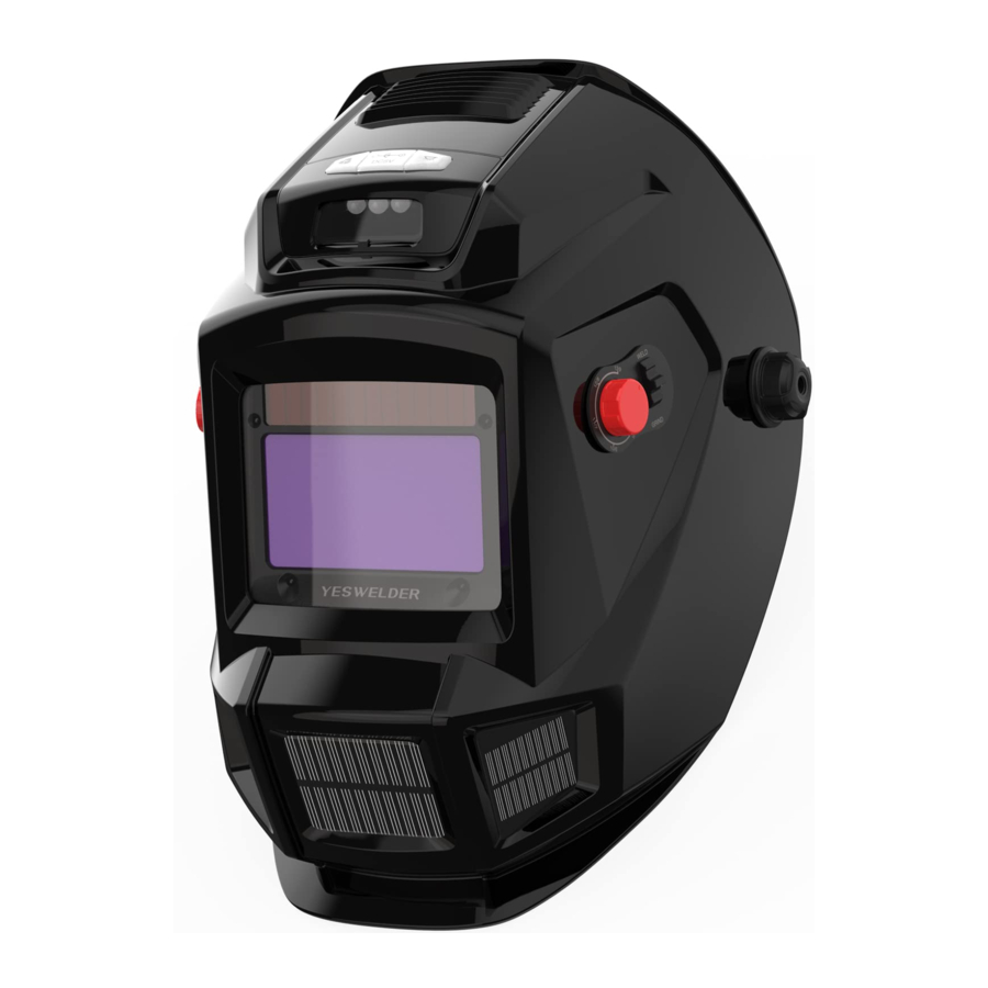
OPERATING INSTRUCTIONS
Product Controls


- Reset Button (See "Reset Button And Low Battery Indicator")
- Low Battery Indicator (See "Reset Button And Low Battery Indicator")
- Variable Shade Control (See "Variable Shade Control")
- Sensitivity Control (See "Shade Selection Chart")
- Lens Delay Control (See "Lens Delay Control ")
- Mode Control Switch
Reset Button And Low Battery Indicator

 The auto-darkening lens turns on (darkens) automatically when welding begins and turns off 15 - 20 minutes after welding stops.
- Reset Button
Press Reset button to check if the lens is working properly.
When the Reset button is pressed, the lens should darken and reto the clear state. Do not use the helmet if the lens does not function as described. (See "Troubleshooting") - Low Battery Indicator
The low battery indicator lights when 2-3 days of battery life remain.
If battery power is low, replace with CR2450 lithium batteries (1 quired).
Lens Delay Control

- Lens Delay Control
The lens delay control is used to adjust the time for the lens to switch to the clear state after welding.
The delay is particularly useful in eliminating bright after-rays present in higher amperage applications where the molten puddle remains bright momentarily after welding. Lens delay adjusts from SLOW: 0.1 second / MIDDLE: 0.4 second / FAST: 0.8 second
Variable Shade Control

(No. 5-9/9-13)
- Variable Shade Control (No. 5-9/9-13)
The shade can be adjusted from shade 5-9 or 9-13 based upon welding process or application (re fer to shade selection chart). Shade is adjusted by setting the 2. MODE CONTROL SWITCH to the proper range, then use the shade dual scale dial to set the desired shade. The mode control switch and dual scale dail are shown above.
- Weld Mode
Used for most welding applications. In this mode the lens turns on when it optically senses a welding arc. Adjust shade, sensitivity, and delay settings as needed. - Cut Mode
Used for cutting applications. In this mode the lens turns on when it optically senses a cutting arc. Adjust shade, sensitivity, and delay settings as needed. - Grind Mode
Used for metal grinding applications. In this mode the lens is fixed at shade No. 4. No lens adjustments are possible
Shade Selection Chart

Reference: ANSI Z49.1:2005
*Start with a shade that is too dark to see the weld zone. Then, go to a lighter shade which gives asufficient view of the weld zone without going below the minimum.
Sensitivity Control

- Sensitivity Control
Cut/Weld Mode
Use control to make the lens more responsive to different light levels in various welding/Cutting processes. Use a Mid-Range or 30-50% sensitivity setting for most applications.
It may be necessary to adjust helmet sensitivity to accommodate different lighting conditions or if lens is flashing On and Off.
Grind Mode
![]() Do not weld in the Grind mode; the lens will not darken.
Do not weld in the Grind mode; the lens will not darken.
 Do not weld in the Grind mode; the lens will not darken.
| Recommended Sensitivity Settings | |
| Stick Electrode | Mid-Range |
| Short Circuiting (MIG) | Low/Mid-Range |
| Pulsed & Spray (MIG) | Mid-Range |
| Gas Tungsten Arc (TIG) | Mid/High-Range |
| Plasma Arc Cutting/Welding | Low/Mid-Range |
| Grind Mode | Grind Position - Far Right (Clockwise) |
ADJUSTING HEADGEAR

 There are four headgear adjustments: headgear top, tightness, angle adjustment, and distance adjustment.
- Headgear Top
Adjusts headgear for proper depth on the head to ensure correct balance and stability. - Headgear Tightness
To adjust, push in the adjusting knob located on the back of the headgear and turn left or right to desired tightness.
![]() If adjustment is limited, it may be necessary to remove the comfort cushion.
If adjustment is limited, it may be necessary to remove the comfort cushion. - Distance Adjustment
Adjusts the distance between the face and the lens. To adjust, loosen both outside tension knobs and press inward to free from adjustment slots. Move forward or back to desired position and retighten. (Both sides must be equally positioned for proper vision) - Angle Adjustment
Four pins on the right side of the headband top provide adjustment for the forward tilt of the helmet. To adjust, loosen the right outside tension adjustment knob then lift on the control arm tab and move it to the desired position. Retighten tension adjustment knob.
![]() When using the back distance adjustment positions, only the back three angle adjustment pins can be used.
When using the back distance adjustment positions, only the back three angle adjustment pins can be used.
REPLACING THE LENS COVERS

 Never use the auto-darkening lens without the inside and outside lens covers properly installed. Welding spatter will damage the auto-darkening lens and void the warranty.
- Outside Lens Cover
- Lens Assembly
- Lens Frame
- Inside Lens Cover
Outside Lens Cover
Push down the snap on the bottom of the lens frame.
Rotate the frame clockwise to take it out. Remove the outside lens cover by pushing it into the helmet and reinstall outside lens cover.
 There is a cable connecting the battery and the lense. Please be careful not to break it.
Inside Lens Cover
Remove the inside lens cover by prying cover from groove in gasket and reinstall a new one.

CHARGE & LIGHT

- Charging Port
- Light Switch
- Fan Switch
- Charging Port
The charging interface, built-in 1200mAh lithium battery, adopting DC 5V round hole charger.
![]()
- Light Switch
Press the button to turn on the light to work in low-light environments
![]()


FAN
- Fan Switch
Detachable fan cover, press the fan switch to make air flow more smoothly, so to reduce harmful gases to the human body and effectively decrease the temperature.


MAINTENANCE
NOTICE - Never use solvents or abrasive cleaning detergents.
NOTICE - Do not immerse the lens assembly in water.
The helmet requires little maintenance. However, for best performance clean after each use. Using a soft cloth dampened with a mild soap and water solution, wipe the cover lenses clean. Allow to air dry. Occasionally, the filter lens and sensors should be cleaned by gently wiping with a soft, dry cloth.
TROUBLESHOOTING GUIDE
| Trouble | Remedy |
| Auto lens not ON — autolens will not darken momentarily when the Reset button is pressed. | Check batteries and verify they are in good condition and installed properly. Also, check battery surfaces and contacts and clean if necessary. Check battery for proper contact and gently adjust contact points if necessary. This is particularly important if the helmet has been dropped. Verify left and right battery trays are installed on the correct sides. |
| Not switching auto-lens stays light and will not darken when welding. | Stop welding immediately: Press the Reset button if lens is Auto-On type. If lens is Manual-On type, make sure the lens is turned On. If power is on, review the sensitivity recommendations and adjust sensitivity. Clean lens cover and sensors of any obstructions. Make sure the sensors are facing the arc; angles of 45° or more may not allow the arc light to reach the sensors. |
| Not Switching —auto-lens stays dark after the weld arc is extinguished, or the auto-lens stays dark when no arc is present. | Fine-tune the sensitivity setting by making small adjustments to the control by turning it toward the "min" setting. In extreme light conditions, it may be necessary to reduce the surrounding light levels. |
| Sections of the auto-lens are not going dark, distinct lines separate the light and dark areas. | Stop welding immediately: The auto-lens may be cracked which can be caused by the impact of dropping the helmet. Weld spatter on the auto lens may also cause cracking. (The lens may need to be replaced; most cracked lenses are not covered by warranty). |
| Switching or Flickering — the auto-lens darkens then lightens while the welding arc is present. | Review the sensitivity setting recommendations and increase the sensitivity if possible. Be sure the arc sensors are not being blocked from direct access to the arc light. Check the lens cover for dirt and spatter that may be blocking the arc sensors. Increasing Lens Delay 0.1 - 0.3 second may also reduce switching. |
| Inconsistent or lighter auto-lens shading in the dark-state, noticeable on the outside edges and corners. | Referred to as an angle of view effect, auto-darkening lenses have an optimum viewing angle. The optimum viewing angle is perpendicular or 900 to the surface of the auto-lens. When that angle of view varies in the dark-state, welders may notice slightly lighter areas at the outside edges and the corners of the lens. This is normal and does not represent any health or safety hazard. This effect may also be more noticeable in applications where magnifying lenses are used. |
HEADBAND INSTALLATION
Description of Headband Installation
Take out the headband, and disassemble it according to the exploded view below

- Sweat Band
- Plastic Nut
- Fix Set
- Adjusting Rack
- Angle Adjusting Shim
- Position Sleeve
- Locking Bolt
- Head Band
- Tightness Knob
 To help us serve you better, go to www.yeswelder.com
WE ALWAYS STAND BEHIND IT
Toll Free (855) 937-4567
Documents / Resources
References
Download manual
Here you can download full pdf version of manual, it may contain additional safety instructions, warranty information, FCC rules, etc.
Download YESWELDER LYG-W700A Series - Auto-Darkening Welding Helmet Manual
Advertisement


Need help?
Do you have a question about the LYG-W700A and is the answer not in the manual?
Questions and answers