Dexter Power MJ10200IIIC-I Manual
Hide thumbs
Also See for MJ10200IIIC-I:
- Legal and safety instructions (52 pages) ,
- Assembly, use, maintenance manual (16 pages)
Table of Contents
Advertisement
Available languages
Available languages
Quick Links
Ө
:
,
,
Ө
ү : 05/2023
ө
ү
/
/
:
«
.
, . 77,
«PARK VIEW», 6
/ Қ
/
қ
ұ
: «
Қ
ө
, 77 ү , «PARK VIEW»
Қ
: 5
ұ қ
қ
ң
ғ
EAN CODE : 3 276000 288855
ATLAS CODE : 861574
ү ұ қ ұ қ
ң
/
.,
.
156
,
ү
ң қ
ғ
,
». 050000,
,
07.
қ
ө
Қ
қ
. 050000, Қ
»
, 07- ң .
, 6-қ
қ
: 08/2016
/
, Қ
ң /
ғ
.
, .
қ
,
/ Original Instructions
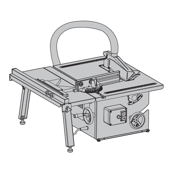
TABLE SAW
MJ10200IIIC-I
Қауіпсіздік техникасы
KZ
жəне пайдалану
бойынша нұсқаулық
RU
i
i
UK
Legal & Safety Instructions
EN
ң
,
қ
қ.,
i
Advertisement
Table of Contents

Related Manuals for Dexter Power MJ10200IIIC-I


Summary of Contents for Dexter Power MJ10200IIIC-I
- Page 1 TABLE SAW MJ10200IIIC-I Қауіпсіздік техникасы жəне пайдалану бойынша нұсқаулық Legal & Safety Instructions Ө , Қ Ө ү : 05/2023 ү ң / ң ө ү ң қ ғ ғ « ». 050000, , . 77, «PARK VIEW», 6 / Қ...
- Page 2 Қ ғ ө ұ қ ғ қ ғ ң Қ ғ ң Қ ғ құ ққ Қ – қ ң қ ү қ ң ғ өң ғ құ ғ ғ қ қ ң ң Қ ғ қ ғ Қ ғ ү...
- Page 3 Қ Ұ Қ Қ - Ү ғ ө ү ; ғ - ңқ қ , ғ ө ң құ ұ ғ ұ қ қ ң • ғ қ ғ ғ - қ қ қ қ қ қ ң . қ ү...
- Page 4 Қ Ұ Қ Қ Ұ Қ құ қ ұ • ұ қ ғ ң . құ ұ ң . құ ң ғ ғ қ қ қ ө ү қ ғ ұ қ ғ ү қ ү • ұ қ ң қ...
- Page 5 Ң Қ Ң Қ “ ө ң қ ” “ ” ғ ң . ұ қ ң ү ң ққ қ ғ құ ғ қ , “ қ қ қ қ ққ қ ғ құ ғ ” ң . • қ ғ...
- Page 6 Ң Қ Ң Қ • қ ү ң ғ қ ң ң ққ қ , қ ңғ қ өң ұ ү қ қ ққ ғ қ қ ғ ғ ң ң құ ғ ң ғ ғ • ұ ү қ ғ...
- Page 7 Ң Қ қ қ қ ң қ ң құ ү ) өң ұ қ қ қ ү ғ өң ұ ө қ қ ң ұ ң ң ө ң Ө ү ң ө ұ қ қ қ қ құ ң ө...
- Page 8 Қ Қ - Ү ғ ұ ү қ ұ қ қ Құ ұ қ (қ қ ғ ғ ) қ ұ қ Ү ң қ қ қ қ қ қ ү ғ қ ұ ү Қ қ ү қ ғ ғ...
- Page 9 ҚҰ Ə ҚҰ Ə Ғ Қ Ə Қ Қ ң ұ қ ғ ң, ү Ө • ң , ғ қ ғ ғ ғ қ ғ қ қ • Құ ұ қ ( ғ ғ қ ғ ғ ) қ ң...
- Page 10 ҚҰ Ə ҚҰ Ə Ө ҚҰ Ғ Ə Қ Ү Қ -Қ Қ • ө құ ғ ң құ ұ қ қ ө ұ қ ү қ -қ қ қ ғ . құ ғ ң , құ ұ қ қ ң...
- Page 11 ҚҰ Ə ҚҰ Ə Ү Ғ Қ Ұ ! 45° қ ғ ү қ қ ! ғ қ ү ң ө қ қ қ ғ 15 - қ қ қ ғ ғ қ қ ! ғ ғ өң ұ ө қ...
- Page 12 ҚҰ Ə ҚҰ Ə Ө Ң • ғ қ , ө құ ғ ү ө • ө құ ғ ң , ғ қ ғ ң . қ ң . • ү өң ұ ң ғ ғ ө ғ , ү ө...
- Page 13 ҚҰ Ə Қ Қ Ө 45° Ұ Ө 45° ө ұ ү ғ қ қ қ ң қ ғ ө - қ ұ қ қ қ ө құ ғ ң . ң . ұ ң ө ғ ң ұ қ қ қ...
- Page 14 Қ Қ Ө Қ қ ң қ ө ң • қ ң қ ұ қ ғ ) қ ң . ұқ ң . қ • Қ ғ қ ң қ құ ғ қ, құ ғ қ ң . ұ ң . Қ ң...
- Page 15 Қ Қ Ө Ө қ ү ө ү ң құ ғ ү ө қ ң , қ қ ұ ғ ү ғ ң ң ү ө ң ұ қ ұ Ө Ө ұ ғ ұ ң ө ң . ү қ ң...
- Page 16 Ө Ө Құ ұ қ Қ ғ қ ғ ү қ ST4.2x 22 ұ қ ө құ ғ ғ қ -қ қ ө ө Қ қ M5x 10 ұ M5x 16 ұ M4 x 8 ұ Құ ұ қ қ M5x 10 ұ...
- Page 17 1. Dexter ө ң ғ ғ . Dexter ө ү қ ұ ө ү қ қ қ ғ ғ қ ғ , ү . Dexter ө ғ ғ . қ ғ ғ , қ Dexter ғ ң ө қ Dexter ү...
- Page 18 MJ10200IIIC-I : 05/2023 " "- 141031, . 1, ( ) : 5 : 08/2016...
- Page 20 EN 847-1. • • . .). • 430 48 • • • • . .). • •...
- Page 21 • • • • • • • • • • • • • • • • •...
- Page 22 » « » « ». • • • • « » « » « • » « ». • » « « » « • » « ». • • 8.14.2 « » « » « • ». « » •...
- Page 23 • • • • • « » « » « ». « • » • « » • • • • • • • • • • • • •...
- Page 24 • « » i • Инструмент нельзя использовать для прорезания пазов, фальцовки или рифления. « • » « » « ». • • • • • « • » « », • • • • • • • • EN847-1, •...
- Page 25 • • Удалите все упаковочные материалы и/или транспортировочные скобы (если имеются). • Проверьте наличие всех частей комплекта. • •...
- Page 26 220–240 ~, 50 1300 S6 20% SI: 900 5000 / 400 x 513 200 x 513 ø210 x 2.8 x ø30 90° 45° 0°–45° EN 61029. • 93,7 • 106,7 LpA = 3 ; Lwa = 3 • S6 = (DR) 20%, •...
- Page 27 • • Открутите семь винтов вставки стола и извлеките их. • Поднимите изношенную вставку стола и извлеките ее. • Установите новую вставку стола согласно обратному порядку демонтажа. • • Но пока не затягивайте фиксаторы (для планки)! • • • • •...
- Page 28 • Поднимите пильный диск на максимальную высоту. • • • ADEO • Включение — нажмите кнопку «I» на выключателе. • Выключение — нажмите кнопку «О» на выключателе. • «OFF». • • Прикрепите планку к корпусу угломера с помощью двух винтов и двух фиксаторов. «ON».
- Page 29 90° 15 . 45°, 0°–45° • . 60°. • (0°–45°). • Снова затяните два фиксатора. 2,5 . 45°, • Ослабьте ручку фиксатора угломера. • Поворачивая параллельную планку, установите желаемый угол на шкале. • Затяните ручку фиксатора угломера. • • Используйте угольник, чтобы выровнять пильный диск в вертикальном положении. •...
- Page 30 • • • Всегда используйте толкатель при выполнении операции продольной резки. • • • Фиксаторы наклона пильного диска заблокированы. • • • При поперечной резке фиксатор угломера затянут. • • Оператор использует защитные очки. • шириной — это продольная резка, а резка с уменьшением длины частей — это •...
- Page 31 • • • . 1/8" • 45° 1" 45°. • 45° • • Прикрепите угловой упор к вспомогательной планке. • • • Положите заготовку в угловой упор. • • После завершения распила выключите станок. 45° « 0°–45°». • • • •...
- Page 32 • • • • • Извлеките внешний фланец и снимите пильный диск с внутреннего фланца. • • • Проверяйте узел щитка пильного диска. • Очищайте режущие элементы с помощью растворителя для смолы. • • • • • Демонтируйте установленные части, которые выступают за пределы станка. •...
- Page 33 • 2012/19/EU • • • −20 ° +50 ° . 90%. • • • Храните устройство в сухом закрытом месте, недоступном для де • • • • • • • +40 ° . 90 %. 20 / ). . 1.
- Page 34 ST4,2 x 22 M5 x 10 M6 x 10 M5 x 12 M6 x 55 6 18 M6 x 10 ST3,5 x 15 M8 x 25 ST3,5 x 9,5...
- Page 35 Dexter Dexter Dexter M5 x 16 M4 x 8 M5 x 10 Dexter. Dexter M5 x 12 6 35 M4 x 8 • • • M5 x 10 M4 x 10 M6 x 30 M5 x 16 • M3 x 20 •...
- Page 37 EN 847 – 1. • HSS ( • • 430 x 48 • • • • • •...
- Page 38 • • • • • « .» • " ", • • • • • • • • • • •...
- Page 39 • • • " " " " " " " " ". • • • • " " • " " " " " ". 8.14.2, " " • • • " " " ". " " " " " •...
- Page 40 • " ". " " " ". " " " " • • • • • • • • • • • • – • " • " " " • " " " ". • • • •...
- Page 41 • • " " " ", • • • • • ₴ • • • EN847-1, • Виберіть правильний пильний диск для заготівки, що буде різатися. • • • • • •...
- Page 42 • • Видаліть пакувальний матеріал і упаковку та/або транспортні кріплення (якщо є). • Перевірте комплект поставки. • Перевірте інструмент і приладдя на наявність транспортних пошкоджень. • Якщо можливо, зберігайте упаковку до кінця гарантійного терміну. ON/OFF " ". 220-240 ~ 50 1300 S6 20% S1:900 5000 400 x 513...
- Page 43 93,7 (A) • 106,7 (A) • Прикріпіть ручку регулювання кута скосу до маховика регулювання кута скосу і затягніть LpA = 3 ; Lwa = 3 S6 = • (DR) 20%, (10 ). • Підвісьте подовжувач столу на циркулярний верстат. . 20% DR •...
- Page 44 • • • • Після вирівнювання затягніть гвинти. • Підніміть пильний диск на максимальну висоту. • • • ADEO • • • Поки не затягуйте фіксувальні ручки-баранчики (для напрямної планки)! • • • • • Вставте напрямну рейку кутового упору в напрямний паз на стільниці робочого столу.
- Page 45 • • Встановіть кутовий упор під потрібним кутом. ON/OFF OFF, • Знов затягніть фіксувальну ручку-баранчик кутового упору. • • • • 45°, ON/OFF • Увімкнути – натисніть кнопку I перемикача. • Вимкнути – натисніть кнопку O перемикача. ON/OFF. OFF. 0° 45°...
- Page 46 • Повертайте маховик регулювання нахилу, поки не побачите потрібний кут (0° - 45°). • Затягніть дві фіксувальні ручки-баранчики. 60°. 45°, 2,5 . • Ослабте фіксувальну ручку кутового упору. • Повернувши паралельну напрямну, встановіть бажаний кут на шкалі. • Затягніть фіксувальну ручку кутового упору. •...
- Page 47 • 0°. • Встановіть напрямну планку на відповідну ширину різання. • • При наближенні до пильного диска завжди використовуйте притискну планку (входить • Завжди штовхайте заготівку до кінця розклинювального ножа. • 15 , • Підніміть пильний диск приблизно на 1/8” над верхньої частиною заготівки. •...
- Page 48 • • • • Будьте дуже обережні на початку різання! 0° 45° 0° • 0°. • • 0° 45° 0° 45° 45° • Встановіть кутовий упор на потрібний кут. • • Міцно утримуйте заготівку впритул до планки кутового упору під час різання. 0°...
- Page 49 • • Перевіряйте складення захисного щитка пильного диска. • Чистіть ріжучі інструменти засобом для видалення гуми і смоли. • • • Зніміть деталі, які виступають над пилкою. • • • • Переносіть інструмент за допомогою ще однієї особи. • При транспортуванні використовуйте оригінальну упаковку, якщо це можливо. •...
- Page 50 – 2012/19/EU 20 /...
- Page 51 ST4,2x 22 0N/0FF M5x 10 M6x 10 M5x 12 M6x 55 6x18 M6x 10 ST3,5 x 15 M8x 25 ST3,5x 9.5...
- Page 52 Dexter Dexter Dexter M5x 16 M4 x 8 M5x 10 Dexter. M5x 12 • M6x 35 • Жодні сторонні особи не проводили ремонту та/або заміни деталей. M4 x 8 • • M5x 10 M4x 10 M6 x 30 M5 x 16 •...
- Page 53 SYMBOLS Eye protection Read the operator’s manual shall be worn Warning! Wear a protective mask Ear protection Danger- Keep hands away shall be worn from blade For woodwork only Class II construction Wear sturdy shoes Wear protective gloves Wear protective helmet This product is recyclable.
-
Page 54: Intended Use
SAFETY INSTRUCTIONS INTENDED USE • Do not operate power tools in explosive atmospheres, such as in the - The table saw is solely intended use for the longitudinal and cross-cutting of solid timber, panel Power tools create sparks HM circular saw blades, whereby only saw blades that comply with the standard EN 847 – 1 may which may ignite the dust or fumes. - Page 55 SAFETY INSTRUCTIONS SAFETY INSTRUCTIONS on. A wrench or a key left attached to a rotating part of the power tool may from those intended could result in a hazardous situation. result in personal injury. • Keep handles and grasping surfaces dry, clean and free from oil and •...
- Page 56 IMPORTANT INFORMATION IMPORTANT INFORMATION is omitted. hand to slip into the saw blade. NOTE 3 If an anti-kickback device is not provided, the phrase “anti-kickback device” is • Do not perform any operation “freehand”. Always use either the rip fence or the mitre omitted.
- Page 57 IMPORTANT INFORMATION IMPORTANT INFORMATION • Never stand on the table saw, do not use it as a stepping stool. Serious injury could occur • Use extra caution when making a cut into blind areas of assembled workpieces. The protruding saw blade may cut objects that can cause kickback. if the tool is tipped or if the cutting tool is accidentally contacted.
-
Page 58: Items Supplied
IMPORTANT INFORMATION ITEMS SUPPLIED You are advised to consider the risks associated with the materials you are working with and to reduce the risk of exposure. You should: - Work in a well-ventilated area. - Work with approved safety equipment, such as those dust masks that are specially designed to lter microscopic particles. -
Page 59: Before Starting The Equipment
ITEMS SUPPLIED BEFORE STARTING THE EQUIPMENT - The table saw must be set up on a stable base, that is, a workbench, or screwed down to a rm Riving knife Locking knob (for auxiliary fence) underframe. Table insert Rip fence - Before starting up all covers and safety equipment must be correctly tted. - Page 60 ASSEMBLY AND OPERATION ASSEMBLY AND OPERATION MOUNTING THE RIP FENCE AND AUXILIARY FENCE WARNING! The blade guard should return to its rest position after the • First, you have to x the clamping elements to the rip fence. workpiece has been cut. •...
- Page 61 ASSEMBLY AND OPERATION ASSEMBLY AND OPERATION MOUNTING AND SET THE MITRE GAUGE OVERLOAD RESET SWITCH • Attach the mitre gauge locking knob and a at washer to mitre gauge body and tighten This saw is equipped with an overload reset switch. It is situated at the immediate top of the locking knob.
- Page 62 ASSEMBLY AND OPERATION ASSEMBLY AND OPERATION BASIC TABLE SAW OPERATIONS WARNING! In order to be able to use the complete adjustment range WARNING! Risk of injury! If the distance between the rip fence and of 45°, the cut height must be reduced accordingly. saw blade is less than 15 cm, the push stick must be used.
- Page 63 ASSEMBLY AND OPERATION ASSEMBLY AND OPERATION RIPPING CROSSCUTTING • Remove the mitre gauge and set the rip fence to appropriate cutting width.. • Remove the rip fence and place the mitre gauge in the mitre groove on the table. • Raise the blade until it is approximately 1/8” above the top of the workpiece. •...
-
Page 64: Maintenance
ASSEMBLY AND OPERATION MAINTENANCE MAKING A 45° MITRE CUT CLEANING Always use rip fence and auxiliary fence plus the angle stop or the mitre gauge to cut 45° mitres. WARNING! Always wear goggles when blowing dust. If operation is Making a 45° cut with the angle stop dusty, also wear a dust mask. -
Page 65: Disposal And Recycling
MAINTENANCE STORAGE • Store the blade wrenches and push stick in the storages (left side and back of the cabinet). WARNING! Arbor shaft has left-hand threads. Be extremely careful • Store unused equipment in a dry, locked place out of the reach of children. •... -
Page 66: Troubleshooting
TROUBLE SHOOTING EXPLODED VIEW Problem Possible cause Solution Machine stops while 1. Saw blade blunt 1. Replace saw blade cutting. 2. Feed is too great 2. Allow motor to cool and proceed working with less pressure Workpiece sticks 1. Saw blade is dull 1. -
Page 67: Part List
PART LIST PART LIST No. Description No. Description No. Description No. Description Locking knob Protect board Guide pole Flat washer Screw ST4.2 x 22 Hex nut M5 Mitre gauge ø Rip fence ON/OFF Swtich Bushing (C) Pointer Clamping block Screw M5 x 10 Screw M5 x 16 Screw M4 x 8 Locking knob... - Page 68 GUARANTEE 1. Dexter products are designed to the highest DIY quality standards. Dexter provides a 24-month warranty for its products, from the date of purchase. This warranty applies to all material and manufacturing defects which may arise. No further claims are possible, of whatever nature, direct or indirect, relating to people and /or materials.
- Page 69 1076500008052301414181 1076500008052301414181 1076500008052301414181 1076500008052301414181 / Made in China 2023...
Need help?
Do you have a question about the MJ10200IIIC-I and is the answer not in the manual?
Questions and answers