Table of Contents
Advertisement
Quick Links
Advertisement
Table of Contents

Subscribe to Our Youtube Channel
Related Manuals for Memjet AS-1180C


Summary of Contents for Memjet AS-1180C
- Page 1 User Guide Digital Color Document Printer MACH 8 (AS-1180C)
- Page 2 However, neither Neopost, Inc. nor any of its agents or employees shall be responsible for any inaccuracies contained herein. ® Memjet is a registered trademark. All other trademarks are the property of their respective holders.
-
Page 3: Table Of Contents
TABLE OF CONTENTS Table of Contents SECTION 1 – GETTING ACQUAINTED ................1 ..............................1 RONT ..............................2 ............................3 RINT NGINE ............................... 4 ) ...................... 5 APACITY UTPUT TACKER OPTIONAL SECTION 2 – INSTALLING THE PRINTER ................6 ........................... 6 RANSPORT NSPECTION ............................... - Page 4 TABLE OF CONTENTS General Tab ............................... 40 Layout Tab ................................. 43 Color Tab ................................44 Import/Export Tab ............................. 46 Services Tab ............................... 46 ............................47 OOLBOX EATURES User Interface Menu ..........................47 Diagnostics Menu ..........................52 Ink Usage Menu ............................ 53 System Settings .............................
- Page 5 TABLE OF CONTENTS ............................. 85 AMS IN THE RINTER Removing Jammed Media ........................85 .......................... 87 LEANING THE RINTER ..................87 LEANING THE OLLERS AND ORWARDING OLLERS ........................... 88 LEANING THE ENSOR ....................89 LEANING THER TEMS INSIDE THE RINT NGINE Grit Rollers (Media Transport Rollers) ....................
- Page 6 TABLE OF CONTENTS NOTES ______________________________________________________ ______________________________________________________ ______________________________________________________ ______________________________________________________ ______________________________________________________ ______________________________________________________ ______________________________________________________ ______________________________________________________ ______________________________________________________ ______________________________________________________ ______________________________________________________ ______________________________________________________ ______________________________________________________ ______________________________________________________...
-
Page 7: Section 1 - Getting Acquainted
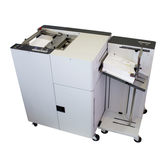
SECTION 1 GETTING ACQUAINTED SECTION 1 – Getting Acquainted Front View Feed Table Controls – Raise and lower Feed Table for loading media. Print Engine Controls On/Off, Paper/Resume and Pause/Cancel Buttons. Storage Compartment – Holds media, ink and other supplies. Top Cover –... -
Page 8: Rear View
SECTION 1 GETTING ACQUAINTED Rear View Feed Table Sensor Output Stacker Power Out – Connect power cord from optional High Capacity Output Stacker here. Outlet is rated for 1A, 115VAC. Main Power Switch, Receptacle and Fuse– Plug in power cord here. Switch turns main power ON/OFF. -
Page 9: Print Engine View
If you are replacing the printhead; it is best to use the “Release Printhead” button from the Toolbox utility. Printhead Cartridge – Memjet Printhead. Produces an 8.5" wide full color print area. Print Ink Channels Button* – Prints 5 bars (1 bar from each ink tank) to indicate how well the Printhead Nozzles are working. -
Page 10: Ink Tank View
SECTION 1 GETTING ACQUAINTED Ink Tank View (Behind the Ink Tank Door) Ink Tank Securing Latches – Used to hold the Ink Tanks securely into the slots and against the electrical contacts within the print engine. CAUTION! Before removing/installing Ink Tanks; please be sure to power-down the Print Engine or press the “Replace Ink Tanks”... -
Page 11: High Capacity Output Stacker (Optional)
SECTION 1 GETTING ACQUAINTED High Capacity Output Stacker (optional) Control Panel – UP button raises Receiving Tray. DOWN button lowers Receiving Tray. Pressing the same button a second time; stops the Tray at its current location. Pressing both buttons simultaneously, for about 6 seconds, repositions the Tray to the “ready”... -
Page 12: Section 2 - Installing The Printer
SECTION 2 INSTALLING THE PRINTER SECTION 2 – Installing the Printer Before using the MACH 8 Printer the following must be done: • Transport Inspection. Upon delivery; inspect packaging and report any issues to the Carrier • Gather Tools • Choose a location for the Printer •... -
Page 13: Operating Conditions
SECTION 2 INSTALLING THE PRINTER Operating Conditions Operation should take place under the following conditions: - At temperatures between +15°C and +35°C (59 °F to 95 °F). - At a relative air humidity between 20% and 80%, non-condensing. - At an atmospheric pressure between 70 kPa and 105 kPa. - Printer and Print Engine should be protected from excessive environmental debris/dust. -
Page 14: Removing The Cardboard Shipping Insert And Shipping Tape
SECTION 2 INSTALLING THE PRINTER Removing the cardboard Shipping Insert and Shipping Tape WARNING! To avoid possible damage to the printer; do NOT plug-in, or power-up, the printer until all shipping materials have been removed; as described below. 1. Open the Top Cover. 2. -
Page 15: Leveling The Printer (Print Engine)
SECTION 2 INSTALLING THE PRINTER Leveling the Printer (Print Engine) IMPORTANT! It is critical that the Printer Engine is level front-to-back and left-to-right. Why is this Important? The printer’s ink delivery systems, and waste ink drainage system, depend on the Print Engine being level to perform properly. -
Page 16: Checking The Tilt Readings
Please allow the Print Engine to remain powered-up for at least 15 minutes before checking/adjusting. 1. Go to the Start Menu, All Programs, Memjet, M Series Driver, then open the “Toolbox”. 2. When the Toolbox opens; on the User Interface screen, find “Tilt”, in the status information along the left side. -
Page 17: Connecting The Printer
SECTION 2 INSTALLING THE PRINTER Connecting the Printer Plugging in the Printer • Check to make sure the Main Power Switch [1] is in the OFF (0) position. • Plug the power cord into the receptacle [1] at the rear of the Printer. •... -
Page 18: Connecting To The Computer
• Printing is not supported for “native” Windows 8/8.1/10 applications (apps that were developed strictly for Windows 8/8.1/10). • Windows 10 users: The uninstall feature will not appear under All Apps, Memjet. To uninstall the driver; go to “Settings”, “System”, “Apps & features”. Then locate and uninstall the “M Series Driver”. -
Page 19: Installing The Printer Software (Driver & Toolbox)
Uninstall the old software before installing the new software. Use the “Uninstall” feature found on your computer system under All Programs, “Memjet”, “M Series Driver”. IMPORTANT: Before installing the Printer software (Toolbox and Driver), you should temporarily disable all antivirus programs and firewalls. - Page 20 SECTION 2 INSTALLING THE PRINTER 6. The License Agreement window opens. Carefully read the “Software License Agreement”. If you agree to the terms, check “I accept…” then click Next>. 7. After a few moments the “Printer Connections” window opens. Click “Configure to print using USB”.
- Page 21 SECTION 2 INSTALLING THE PRINTER 11. The “Finished software installation” window opens. Do not select (check) the Print Test Page as the Printer is not set up yet. If desired; you can select (check) the “Set this printer as the default printer” at this time. Then click Finish.
-
Page 22: Connecting The Printer Via Network (Ethernet Port)
Once the software installation is complete; you can proceed to the next step. 2. Open the M Series “Toolbox” utility. To open the Toolbox utility; click on Start, All Programs, Memjet, M Series Driver, Toolbox. The Toolbox will open in a Web Browser (Example: Internet Explorer) window. - Page 23 Opening (launching) the “Toolbox” utility over an Ethernet connection: To open the Toolbox utility; click on Start, All Programs, Memjet, M Series Driver, Toolbox. If you have more than one copy of the M-Series Driver installed, you may be prompted to choose the device you want the Toolbox to connect to.
-
Page 24: Installing The Ink Tanks
SECTION 2 INSTALLING THE PRINTER Installing the Ink Tanks The Printer uses five Ink Tanks (two Black, one Cyan, one Magenta, and one Yellow). The Ink Tank is a delicate, precision device. Handle with extreme care to avoid damage. Ink Tank Anatomy WARNING! The ink used in this system may be harmful if swallowed. -
Page 25: Procedure (Installing The Ink Tanks)
ON/OFF button. Wait about 45 seconds for the print engine to power-up (ON/OFF button will illuminate). 2. Open the M Series Toolbox. Go to All Programs, select the “Memjet” folder, select the “M Series Driver” folder and Open the “Toolbox”. - Page 26 SECTION 2 INSTALLING THE PRINTER 4. Open the Ink Tank Door (hinged at bottom). 5. Open all three Ink Tank Securing Latches [A]. 6. Remove the new Ink Tank(s) from packaging. Ink Tank Door 7. Insert the new Ink Tanks (labels up) into their appropriate color slots [B].
- Page 27 SECTION 2 INSTALLING THE PRINTER 10. Verify Tank Recognition. Watch the Toolbox screen on your computer. You should see all the ink colors fill-in; if all the Ink Tanks are properly installed and recognized. NOTE: The image to the right shows used Ink Tanks installed.
-
Page 28: Installing The Printhead Cartridge
SECTION 2 INSTALLING THE PRINTER Installing the Printhead Cartridge The Printer uses a single Memjet® printhead cartridge. The Printhead Cartridge is a delicate, precision device. Handle with extreme care to avoid damage and issues that could degrade print quality. ATTENTION... - Page 29 SECTION 2 INSTALLING THE PRINTER CAUTION • Use electrostatic discharge (ESD) handling precautions. • Hold the Printhead Cartridge by the handles ONLY. • DO NOT touch the Ink Couplings, nozzle surface or electrical contacts. • DO NOT unpack the Printhead Cartridge until the Printer is ready for installation.
-
Page 30: Procedure (Installing The Printhead Cartridge)
SECTION 2 INSTALLING THE PRINTER Procedure (Installing the Printhead Cartridge) This procedure assumes that you are installing a Printhead Cartridge into a printer that does NOT have a Printhead Cartridge installed. If your printer already has a Printhead Cartridge installed, and you wish to replace the Printhead Cartridge;... - Page 31 SECTION 2 INSTALLING THE PRINTER 5. [A] Carefully remove the Printhead Cartridge from the foil packaging. Tear at notch or cut end with scissors. [B] Remove the protective plastic cover. Hold the Printhead by the handle and unclip the cover from the Printhead. [C] Remove protective strip from the Printhead Electrical Contacts.
- Page 32 SECTION 2 INSTALLING THE PRINTER 7. Open the Print Engine Clamshell. Use both hands to release both latches at the same time. 8. Using a lint-free cloth soaked with deionized or distilled water, wet the entire Printhead Nozzle area. Be liberal with the amount of water you leave behind on the nozzles (the thin dark line on bottom of printhead cartridge).
- Page 33 SECTION 2 INSTALLING THE PRINTER If you reach the end of the priming process and the printhead failed to prime (one or more of the ink tubes have not filled with ink): Release the printhead (using the Release Printhead feature from the Toolbox), Once the latch opens, carefully retract the latch fully.
-
Page 34: Installing/Removing The Head Media Guide
SECTION 2 INSTALLING THE PRINTER Installing/Removing the Head Media Guide The Head Media Guide is used to flatten the media, as it enters under the printhead, to help reduce media contact with the printhead. If the media makes contact with the printhead this may result in: - Scuff Marks - black streaks deposited on surface of media - Smearing/Smudging of wet image, which can also deposit additional ink on the printhead surface;... - Page 35 SECTION 2 INSTALLING THE PRINTER 4. [C] Push the Guide to the right, to lock it in place. NOTE: While the Clamshell is still open, verify that the Head Media Guide is aligned with the Printhead Cartridge as shown in “C”. 5.
-
Page 36: Section 3 -Installing The Output Stacker (Optional)
SECTION 3 INSTALLING THE OUTPUT STACKER SECTION 3 –Installing the Output Stacker (optional) The optional High Capacity Output Stacker is designed to work automatically with the MACH 8 Printer. Before using the Output Stacker the following must be done: • Unpack the Output Stacker •... -
Page 37: Section 4 - Operating The Printer
SECTION 4 OPERATING THE PRINTER SECTION 4 – Operating the Printer MACH 8 Control Panel Functions There are 5 Buttons on the Control Panel of the MACH 8 to operate the Feed Table and the Print Engine. PRINT ENGINE For The Print Engine: The 3 buttons on the right control the Print Engine: ON/OFF, PAPER/RESUME and PAUSE/CANCEL. -
Page 38: Print Engine Status Light (Led) Indicators
SECTION 4 OPERATING THE PRINTER Print Engine Status Light (LED) Indicators The lights (LED’s), on these three control panel buttons, indicate the status of the Print Engine. Flashing SLOW = 1 time per second Flashing FAST = 3 times per second NOTE: To obtain additional detail about the printer’s condition, please open the Toolbox utility. - Page 39 SECTION 4 OPERATING THE PRINTER Print Engine Status Light Indicator Chart (continued) Additional Details, Possible LED Sequence Print Engine Status Solution or Action Press the RESUME button to continue printing. Job can also be resumed by clicking on the “Clear Error” button in the Toolbox. Press the CANCEL button to cancel the Printing Paused job and clear the job from the computer’s...
- Page 40 SECTION 4 OPERATING THE PRINTER Print Engine Status Light Indicator Chart (continued) Additional Details, Possible LED Sequence Print Engine Status Solution or Action Printer is Performing Maintenance (Cleaning, Circulating Ink, etc..) Wait for lights to stop blinking. Toolbox = MAINTENANCE_BUSY Canceling Job.
-
Page 41: For The Feed Table
SECTION 4 OPERATING THE PRINTER For the Feed Table: The Up and Down buttons control the Feed Table: UP (Green Arrow): Press to raise the Table for loading and positioning media. It will stop automatically when the media stack or Table reaches the Top Sensor. -
Page 42: Setting Up The Feed
SECTION 4 OPERATING THE PRINTER Setting up the Feed 1. Lower the Feed Table [A], Press the “Down” Button, on the Control Panel, to lower the Feed Table. 2. Slide the Right Media Side Guide [C] , all the way to the right. - Page 43 SECTION 4 OPERATING THE PRINTER 5. Close and Latch the Feed Roller Assembly [E] . While holding the Feed Roller Assembly down/closed, slide the latches forward [in opposite direction of arrow] and tighten the two Thumbscrews [D]. 6. Load Media Place a small stack of Media stack onto the Feed Table [A].
- Page 44 SECTION 4 OPERATING THE PRINTER 10. Adjust for Media Thickness. . The Media Thickness Adjustment Knob [H] sets the uppermost stopping point of the Feed Table to accommodate single sheets of paper or heavier card stock/cardboard Normal/Thin Media (sheets of paper): Turn Thickness Adjustment Knob fully counter-clockwise unit it stops.
- Page 45 SECTION 4 OPERATING THE PRINTER Feed Alignment Roller Latch Valid for S/N 100038958 and higher. The following item/feature is not present in older units. Occasionally, during normal feeding, the Feed Alignment Roller [A] (which normally helps keep the media aligned) may start pulling the media out of line.
-
Page 46: Printer Driver Properties
SECTION 4 OPERATING THE PRINTER Printer Driver Properties Valid for M Series Driver version R15 NOTE: The R15 Driver was developed for use with printer firmware version 20180323. They must be used as a set. If you try to use this Driver with other printer firmware versions, some of the Driver properties/features may not work. - Page 47 SECTION 4 OPERATING THE PRINTER Optimization” is selected. If this happens; deselect (uncheck) "Mask Optimization" which usually corrects the issue. (Remember to check/uncheck box when changing applications.) o Back Page – Unavailable unless Printer is attached to “Duplex Unit” (Duplex Unit was not available at time of publication).
- Page 48 SECTION 4 OPERATING THE PRINTER After defining a “custom media size”; enter your desired “Media Name” and press “Save”. Tip: When defining the width of a “custom media size” that measures between 8.5 and 9.5 inches wide; please set the width value to 8.5” (max print width of printer). Example: #10 Env (9.5”W x 4.13”H), feeding long-edge first.
-
Page 49: Layout Tab
SECTION 4 OPERATING THE PRINTER o Best provides 1600 x 1600 dpi, at 6 ips. Use when high quality images are required. NOTE: The “Half Speed” selection is not available in the “Best” print quality mode. • My Print Settings – Allows you to save or recall your custom Driver settings for various jobs. When you save or replace a “My Printer Settings”... -
Page 50: Color Tab
SECTION 4 OPERATING THE PRINTER positive value = shift down (purge later) During normal operation, the printhead spits a small amount of ink into the gap between pieces; to keep the nozzles clear and hydrated. For irregular-shaped pieces (like an open envelope flap), the Paperpath Entry sensor may “see”... - Page 51 SECTION 4 OPERATING THE PRINTER will be needed to obtain the desired printed output. The adjustments made do not make any changes to the original artwork/file, but the driver settings can be saved using “My Printer Settings”, located under the General tab.
-
Page 52: Import/Export Tab
SECTION 4 OPERATING THE PRINTER Import/Export Tab Import/Export is used to preserve any custom Media Sizes, Watermarks and Print Settings, you may have added/created for various jobs. • Watermarks – select to export/import • Media Sizes – select to export/import •... -
Page 53: Toolbox Features
SECTION 4 OPERATING THE PRINTER Toolbox Features Valid for printers with Firmware version 20151228 installed. Once the Printer Driver is installed you have access to the Printer Toolbox. The Toolbox lets you monitor ink usage, perform diagnostic checks, print reports and run maintenance tasks on the Printer from your computer. - Page 54 CAUTION: Over-use of these features can negatively affect print quality and printer performance. Note: The Memjet printhead contains 70,400 nozzles. Each nozzle is a fraction of the diameter of a human hair. Under normal use; it is not uncommon for a small percentage of nozzles to become clogged/dehydrated.
- Page 55 SECTION 4 OPERATING THE PRINTER may need to be serviced. Due to the fact that a dirty/worn/damaged “wiper roller” can cause damage to a new printhead; it is recommended that the “wiper roller” be replaced whenever the printhead is replaced. Please contact your service preventative to have them perform this procedure. Do NOT use the above features to try to reduce “scuff marks”...
- Page 56 SECTION 4 OPERATING THE PRINTER • Mid-Job Servicing – Allows the user to adjust the frequency of printhead cleaning (maintenance) during a print job. The values have been changed to page-based frequency control; which is more intuitive than previous versions. The following choices are available: 50 (default)*, 100, 250, 500, 1000 or 2500 pages.
- Page 57 SECTION 4 OPERATING THE PRINTER [D] SERVICE Buttons. WARNING! These buttons should only be used by an experienced/trained user. Improper usage can cause damage to the system. These buttons control functions that require the machine to be “out of service”, for extended periods of time, while procedures are being performed.
-
Page 58: Diagnostics Menu
SECTION 4 OPERATING THE PRINTER [E] Display Language – Selects the language the Toolbox information will be displayed in. PLEASE BE SURE TO HIT "SUBMIT" AFTER CHANGING THIS SETTINGS [F] Firmware Download – This feature is used to update the firmware in the printer. WARNING: This process should only be performed by a qualified support representative. -
Page 59: Ink Usage Menu
Media Size (Width x Length) is used, as a factor, in this estimation process. NOTE: Memjet estimates nozzle life at ~125,000* linear inches of continuous printing. *This is NOT an expression of Warranty. Individual results will vary. - Page 60 SECTION 4 OPERATING THE PRINTER • Job Cost Settings – The operator should enter the average amount paid for a single Ink Tank (estimator internally multiplies this figure by 5) and the amount paid for the printhead; then press “Submit”. These values are then used to calculate the “Estimated Page Cost”...
-
Page 61: System Settings
SECTION 4 OPERATING THE PRINTER System Settings Set up a network connection for the Printer. Also set and configure Printer Date and Time. Note: To access and change these printer parameters; you must initially install the printer Driver via USB and connect to the printer via USB. - Page 62 SECTION 4 OPERATING THE PRINTER • Date and Time – Enter or change the way the date and time will appear in the Printer Status section of the Toolbox screens. Enter or change Date and Time: 1. Open the User Interface screen, click “System Settings.”...
-
Page 63: Service Menu
SECTION 4 OPERATING THE PRINTER Service Menu For authorized personnel only. Provides a qualified support representative, with access to advanced printer control and troubleshooting menus. A password is required to open the following “Service Menu” features. • Printer Maint Config •... -
Page 64: Printing
SECTION 4 OPERATING THE PRINTER Printing Once the printer installation and setup is complete, you are ready to start printing. Please see the section titled “Software Setup Information” for details on how to setup the computer software to print to the printer. If a printhead was recently installed or the printer was left powered OFF for more than a few hours;... -
Page 65: Section 5 - Software Setup Information
SECTION 5 SOFTWARE SETUP INFORMATION Section 5 – Software Setup Information Once the Printer Driver is installed on your computer and the Printhead is primed, you are ready to start printing. Setup your job and send it to the Printer. The Printer will start and print General Software Setup Info Note: The following information assumes you have the M Series Driver v13 or higher installed. -
Page 66: Adobe ® Acrobat/Reader Setup Tips
SECTION 5 Software Setup Information ® Adobe Acrobat/Reader Setup Tips In general, printing a PDF from Adobe Acrobat/Reader is straight-forward and easy. However there are a few limitations and quirks that you should be aware of. 1. Original PDF should be designed for the piece size and orientation you plan to use. Adobe Acrobat has some nice controls for changing orientation and adjusting the image size to fit the media size you select;... -
Page 67: Setting U P A Job In Microsoft Word ® (2007)
SECTION 5 SOFTWARE SETUP INFORMATION ® Setting Up a Job in Microsoft Word (2007) ® Valid when using Microsoft Word 2007 and the M Series Driver version R14.2. Before you begin laying-out the document; make sure the “M Series Driver” has been selected as your “default printer”... - Page 68 SECTION 5 Software Setup Information 11. Click on the “Office Button” and then select “Print”. Make sure the “M Series Driver” is showing as your printer name. 12. Click on the “Properties” button. The “M Series Driver Properties” windows will open.
-
Page 69: Section 6 - Operating The Stacker (Optional)
SECTION 6 OPERATING THE OUTPUT STACKER SECTION 6 – Operating the Stacker (optional) . The Automatic High Capacity Output Stacker was designed to work with the MACH 8 printer. With these simple instructions; you should find it very easy to set up and use. CAUTION KEEP HANDS/FEET AND OTHER BODY PARTS OUT FROM UNDER THE RECEIVING TRAY. -
Page 70: Output Stacker Status Light (Led) Indicators
SECTION 5 OPERATING THE OUTPUT STACKER Output Stacker Status Light (LED) Indicators The lights (LED’s), on these two control panel buttons, indicate the status of the Output Stacker. Output Stacker Status Light Indicator Chart Additional Details, Stacker Status Possible Solution or Action Main power switch is OFF Check/Turn ON Main Power switch. -
Page 71: Output Stacker Setup
SECTION 5 OPERATING THE OUTPUT STACKER Output Stacker Setup 1. Once the Stacker is powered on, it should automatically reposition the Receiving Tray to the “ready” position (top of media stack or top of Tray will be located about 1/4” below the stack height sensor). -
Page 72: Section 7 - Operator Maintenance
SECTION 7 MAINTENANCE SECTION 7 – Operator Maintenance This section covers how to perform routine operator maintenance on the printer; including Ink Tank care, Printhead care, clearing paper jams, replacing Ink Tanks, replacing Printhead Cartridge, replacing sheet separators. If printer maintenance or service is needed beyond the scope of what is covered in this section; please contact your Dealer/Distributor for support. -
Page 73: Ink Tank Storage & Shelf Life
SECTION 7 MAINTENANCE 5. Clean the Ink Level Prism [A] and QA Chip contacts [B] with a clean, dry, lint-free cloth. NOTE: You can dampen the cloth with distilled water to wipe the Prism, but DO NOT get the QA Chip contacts wet. Tip: A soft pencil eraser can also be used to lightly clean the QA Chip contacts. -
Page 74: Ink Tank Disposal
SECTION 7 MAINTENANCE Ink Tank Disposal The Ink Tank may be disposed of in a normal manner. Clean up spills with soap and water. Abrasive soap is effective in cleaning ink off your hands. Cleaning the Printhead Cartridge The Printhead Cartridge is cleaned automatically; each time the printer is turned ON, before each job, periodically during the print job, and when a User Maintenance Level routine is performed by the operator. -
Page 75: Manual Printhead Cleaning
SECTION 7 MAINTENANCE Manual Printhead Cleaning: NOTE: We recommend the use of nitrile powder-free gloves for this process. As a last resort, if running the built-in “... Clean Printhead” features don’t help improve print quality; the printhead cartridge can be cleaned manually. 1. -
Page 76: Replacing The Printhead Cartridge
SECTION 7 MAINTENANCE Replacing the Printhead Cartridge The following procedure describes how to remove the Printhead Cartridge from the printer. ATTENTION If you experienced fuzzy print quality or an abrupt failure in a particular area of nozzles on the previous printhead; we recommend that you have the service station inspected/cleaned and the wiper roller replaced, before installing the new printhead. -
Page 77: Printhead Storage & Shelf Life
SECTION 7 MAINTENANCE 8. Once the old Printhead Cartridge has been removed; please refer to the section titled “Installing the Printhead Cartridge”; to install the new Printhead Cartridge. Printhead Storage & Shelf Life Properly stored, unopened, Printhead Cartridges have a shelf life of up to 1 year. °... -
Page 78: Inspecting & Cleaning The Lip Of The Capping Station
SECTION 7 MAINTENANCE Inspecting & Cleaning the Lip of the Capping Station The Capping Station (Cap) is part of the Service Station. When the printer is idle, the Service Station automatically caps the printhead to keep the nozzles hydrated. Excess ink can accumulate on the Lip of the Cap. This commonly occurs after a printhead cartridge is installed and the system is primed. -
Page 79: Inspecting The Wiper Roller
SECTION 7 MAINTENANCE Inspecting the Wiper Roller The Wiper Roller should be routinely inspected for signs of wear and debris. NOTICE! If you have not been trained or are uncomfortable performing this task, please contact your service support representative. Directions: 1. -
Page 80: Cleaning/Replacing Service Station Items
SECTION 7 MAINTENANCE Cleaning/Replacing Service Station Items The Service Station contains separate areas/devices that are used to perform the following tasks. • Cleaning. The Wiper Roller cleans the Printhead nozzles of excess ink and debris. • Printing/Purging. The Printing Platen acts as a base to support media during printing. It also contains a purging area;... - Page 81 SECTION 7 MAINTENANCE 3. Power-up the printer. 4. Open the Printer Toolbox. In the User Interface window, press the “Eject Service Station” button. 6. Once the Service Station has ejected; power OFF the printer. Press the ON/OFF button once and wait about 45 seconds for the print engine to power off (all control panel light’s off).
-
Page 82: Cleaning The Service Station
SECTION 7 MAINTENANCE Cleaning the Service Station Caution: Please be sure that you are using proper cleaning techniques to clean items that come in contact with the printhead. Use only distilled or deionized water and lint free cloths. If you don’t follow this rule, you will introduce contamination into the printhead;... -
Page 83: Wiper Motor Assembly Removal And Cleaning
SECTION 7 MAINTENANCE 2. Carefully close the latches. Make sure the latches are fully locked and then tighten the latch retaining screws [C] (don’t over-tighten). Wiper Motor Assembly Removal and Cleaning Removal: 1. Disconnect (unplug) the wiper motor cable from the Service Station Printed Circuit Board [A]. -
Page 84: Printing Platen And Capping Station Removal And Cleaning
SECTION 7 MAINTENANCE TIP: If you are planning to clean the Service Station Tray; don’t re-install this component until you have completed the Service Station Tray cleaning process. Printing Platen and Capping Station Removal and Cleaning Removal: Both of these items simply lift out for removal from the Service Station. Cleaning: 3. -
Page 85: Installing The Service Station
SECTION 7 MAINTENANCE Installing the Service Station CAUTION THIS PROCESS MUST BE PERFORMED BY A QUALIFIED/TRAINED PERSON. NOTICE: Due to the technical nature of this procedure; it should only be performed by a qualified technical support person or someone that has been properly trained on this procedure. Please contact your technical support representative. - Page 86 SECTION 7 MAINTENANCE 6. Slide the Cable Securing Latch open on the Service Station Circuit Board; as shown below. Closed Opened 7. Locate the Ribbon Cable (from within the Service Station Slot). Insert the Ribbon Cable (blue side up) into the space under the Cable Securing Latch [1].
- Page 87 SECTION 7 MAINTENANCE 9. Look down through open area, in the Print Engine, to make sure the Service Station is aligned with the “Bar”; (Service Station Drive Shaft) as shown. If the Printhead Cartridge is not installed (has been removed), you can look down through the top of the Print-Engine, through the Printhead Cartridge opening.
-
Page 88: Still Experiencing Print Quality Issues
SECTION 7 MAINTENANCE 11. Turn the printer’s Main Power Switch ON; then press the control panel’s ON/OFF button. After printer initialization (~45 seconds) the Print Engine will automatically pull the Service Station the rest of the way in. NOTICE: If the Service Station should get jammed during this process (you hear motor stall noise or gear slipping noise);... -
Page 89: Inspecting/Replacing The Waste Ink Tray
SECTION 7 MAINTENANCE Inspecting/Replacing the Waste Ink Tray The Waste Ink Tray (123-2487) is filled with an absorbent material, used to capture the waste ink that drains from the Service Station. 1. If the printer is on; press the ON/OFF button to power-down the print engine. Wait about 45 seconds until the system shuts down (all control panel lights will go off). -
Page 90: Replacing The Sheet Separators
SECTION 7 MAINTENANCE Replacing the Sheet Separators The sheet separators (43-106-10) insure separation of the pieces as they are being fed. If you experience double sheet feeding, and adjusting for Media Thickness (See Feed Setup) does not prevent this, it may be time to replace the separators. -
Page 91: Jams In The Printer
SECTION 7 MAINTENANCE Jams in the Printer When the printer detects a media feed problem, it will stop automatically. Depending on where the media stops; the message “PAPERPATH_PAPERJAM” or “PAPERPATH_FEED_TIMEOUT” will be displayed in the Toolbox. Once the jam has been removed from the system and the print engine is closed; press the PAPER/RESUME button on the control panel or press the Clear Error button in the Toolbox to continue printing. - Page 92 SECTION 7 MAINTENANCE Forwarding Roller Section: Release the Forwarding Roller Guide Assembly by opening the Latch [C]. Slide the Assembly toward the Control Panel [D]. Carefully lift the Assembly up [E]. Remove jammed media. Reinstall the Assembly. CAUTION DO NOT BEND, PINCH OR CUT THE INK LINES LOCATED DIRECTLY IN FRONT OF THE ASSEMBLY.
-
Page 93: Cleaning The Printer Body
SECTION 7 MAINTENANCE Cleaning the Printer Body WARNING THE PRINTER IS A PRECISION MACHINE THAT SHOULD BE CLEANED REGULARLY TO INSURE MANY YEARS OF SERVICE. BEFORE PERFORMING ANY MAINTENANCE, DISCONNECT THE MACHINE FROM ITS POWER SOURCE! DO NOT REMOVE SIDE COVERS! HIGH VOLTAGES PRESENT. Clean the Printer regularly to remove accumulated paper dust and ink. -
Page 94: Cleaning The Feed Sensor
SECTION 7 MAINTENANCE Cleaning the Feed Sensor The Feed Sensor is located between the Feed Roller Assembly and the Print Engine. It is used to control the delivery of media to the print engine. TIP: If the Toolbox, Cutsheet Feeding Mode is set to “Safe Feed” and you are getting blanks fed at the end of every job (last piece may stop inside print engine), then the Feed Sensor may not be working properly (dusty/dirty). -
Page 95: Cleaning Other Items Inside The Print Engine
SECTION 7 MAINTENANCE Cleaning Other Items inside the Print Engine Areas in the Print Engine can become glazed with a buildup of dust, paper lint and accumulated ink and need to be cleaned regularly. This section covers the procedures for cleaning the following items. Grit Rollers (Media Transport Rollers) Media (Paperpath) Sensors Capping Station Lip... - Page 96 SECTION 7 MAINTENANCE 5. Use the procedures, as outlined below, to clean the following items. Grit Rollers [A]: Entry Mark Clean as needed using a small stiff-bristled brush (toothbrush), lightly moistened with distilled water. Do NOT use anything other than distilled water to clean the Rollers.
-
Page 97: Cleaning The Ink Revolver Couplings
SECTION 7 MAINTENANCE Cleaning the Ink Revolver Couplings This process should be performed just before a printhead cartridge is installed or re-installed; to remove contaminated/dry ink and other debris from the Ink Revolver Couplings. If this step is skipped; the printhead and or ink system could become contaminated resulting in an increase in print quality issues. -
Page 98: Printer Maintenance Schedule
SECTION 7 MAINTENANCE PRINTER MAINTENANCE SCHEDULE General, periodic maintenance is needed to keep the Printer in good working order. Many tasks can be performed by operators with basic supplies, no special tools needed. Other tasks should only be performed by trained service personnel. NOTE: High volume usage may require more frequent maintenance. MAINTENANCE TYPE COMPONENTS / TASKS DAILY... -
Page 99: Preparing Printer For Transport
SECTION 7 MAINTENANCE Preparing Printer for Transport Please use this procedure if you ever need to transport the printer to a new location or ship the printer. Please refer to the appropriate sections in the manual for details on installing/removing items from the printer. - Page 100 SECTION 7 MAINTENANCE 9. Remove the Printhead Cartridge and install protective covers on printhead. Be careful to avoid ink spills (drips) and stains during this process. Store Printhead Cartridge in a sealed plastic bag with a damp cloth. CAUTION: Make sure the cartridges electrical contacts are dry before re-installing printhead. 10.
- Page 101 SECTION 7 MAINTENANCE NOTES ______________________________________________________ ______________________________________________________ ______________________________________________________ ______________________________________________________ ______________________________________________________ ______________________________________________________ ______________________________________________________ ______________________________________________________ ______________________________________________________ ______________________________________________________ ______________________________________________________ ______________________________________________________ ______________________________________________________...
-
Page 102: Section 8 - Troubleshooting Guide
SECTION 8 TROUBLESHOOTING SECTION 8 – Troubleshooting Guide The following troubleshooting guides are provided to assist you in solving any problems that might occur with the Printer. We have tried to make them as complete as possible. The best advice we can offer is to make sure that the system is set up properly, plugged in, and that it has an adequate supply of ink before attempting to troubleshoot any problem. -
Page 103: Examples Of Print Quality Issues (Including Possible Causes And Solutions)
Examples of Print Quality Issues (including possible causes and solutions) The Memjet printhead cartridge contains 70,400 inkjet nozzles. These nozzles are divided into ten rows; two rows of nozzles for each color channel. Due to the high number of nozzles; it is not uncommon for some nozzles to become contaminated, dehydrated or clogged. -
Page 104: Clogged/Damaged/Dead Nozzles
SECTION 8 TROUBLESHOOTING Clogged/Damaged/Dead Nozzles: Clogged/damaged/dead/ nozzles will normally show as thin, crisp, vertical lines of missing color. Multiple adjacent nozzles, with same issue, will show as wider, crisp, vertical lines of missing color. Clogged nozzles are normally due to Printhead nozzle dehydration or partial contamination. Damaged nozzles are normally due to improper cleaning or debris on wiper roller causing damage to head. -
Page 105: Color Mixing Issues
SECTION 8 TROUBLESHOOTING Color Mixing Issues: Color mixing will show as muddy, mottled or distorted (grainy) colors. Color mixing occurs when the ink from one color channel crosses over into another color channel. Since the inkjet nozzle rows are located very close to one another (ten rows of 7,040 nozzles, located within a 0.8 mm space), it is easy for partials or fibers to create bridges across color channels. -
Page 106: Scuff Marks And Smudging Issues
SECTION 8 TROUBLESHOOTING Scuff Marks and Smudging Issues: Scuff Marks occur when the media makes contact with an area of the printhead that has ink on it. Smudging occurs when the wet image, on the media, makes contact with something (most commonly the printhead) before it is dry. - Page 107 SECTION 8 TROUBLESHOOTING Smudging: Here is an example of “smudging” that occurred when an area of this page, with a wet image, made contact with the printhead. Note: There are also scuff marks in this example. As mentioned previously; smudging will increase the chance for scuff marks;...
-
Page 108: Fuzzy/Distorted Print
SECTION 8 TROUBLESHOOTING Fuzzy/Distorted Print Fuzzy/distorted print can occur for a number of reasons; listed/shown below. Problem: Poor original image quality (less than 300 dpi). Solution: Use high quality images. Problem: Choosing to print image in low resolution from software application. Solution: Set image to highest resolution possible from software application. -
Page 109: The Ink Tank(S)
SECTION 8 TROUBLESHOOTING The Ink Tank(s) CONDITION PROBLEM SOLUTION Installed New Ink Tank and One or more of the “septum Try removing and re- needles” didn’t fully puncture the installing the Tank. See shortly after the related Ink Channel (color) stopped septum seal on the new Ink Tank. -
Page 110: The Printhead Cartridge
TROUBLESHOOTING The Printhead Cartridge The Memjet printhead cartridge contains over 70,000 inkjet nozzles. These nozzles are divided into ten rows; two rows of nozzles for each color channel. Due to the very tiny size of each nozzle and the high number of nozzles;... - Page 111 SECTION 8 TROUBLESHOOTING The Printhead Cartridge (continued) CONDITION PROBLEM SOLUTION System will not prime the Printhead nozzles dry (air pulled Wet the Printhead nozzles using distilled water and a printhead after installing through nozzles; not allowing system to create vacuum) wet, lint-free cloth.
-
Page 112: The Printer
SECTION 8 TROUBLESHOOTING The Printer NOTICE: The printer will not print if any of the five ink tanks are empty or missing. Dots or Lines Printed on Media CONDITION PROBLEM SOLUTION A thick horizontal black line Purge Bar is hitting To help keep nozzles from drying (clogging);... -
Page 113: Service Station Problems
SECTION 8 TROUBLESHOOTING Service Station Problems WARNING! Many of the issues related to Service Station function will require a qualified Service Person, or properly trained person, to diagnose and fix these issues. If you haven’t been properly trained on or don’t feel comfortable performing these procedures;... -
Page 114: Interface Communication Problems
SECTION 8 TROUBLESHOOTING Interface Communication Problems CONDITION PROBLEM SOLUTION M Series Driver does not Wrong USB port selected in “M Verify that you are selecting the respond to printer being Series Driver”. appropriate USB port in the connected via USB. driver Ports Tab. -
Page 115: Feeding Problems
SECTION 8 TROUBLESHOOTING Feeding Problems CONDITION PROBLEM SOLUTION Intermittent feeding Side Guides set too tight to media. Readjust Side Guides. Dirty Feed Rollers. Clean the Feed Roller with distilled water and a cloth. Do NOT use any solvents as they may damage Rollers. Paper stuck together Fan media before placing it in Printer. -
Page 116: Errors And Warnings
SECTION 8 TROUBLESHOOTING Errors and Warnings Printer Alert Window Messages Messages sent from the driver and displayed on PC screen in a small popup window. MESSAGE SOLUTION Cleaning in Progress Wait until the message disappears. The printer will start printing your job once the cleaning process has completed. -
Page 117: Toolbox System Status Messages
SECTION 8 TROUBLESHOOTING Toolbox System Status Messages Displayed, in red, in the M Series Toolbox utility. Valid for printers with firmware version 20151228 or higher installed. SYSTEM STATUS PROBLEM SOLUTION PAPERPATH_FEED_TIME Out of Paper Load media into printer and press the Media is not reaching PAPER/RESUME button. - Page 118 SECTION 8 TROUBLESHOOTING Toolbox System Status Messages (continued) SYSTEM STATUS PROBLEM SOLUTION X = Color. Ink Tank replacement will be necessary X_INK_LOW One or more Ink Tanks soon. Reorder Ink Example: CYAN_ INK_LOW are low on ink. X = Color or MULTI Replace empty Ink Tank(s).
- Page 119 SECTION 8 TROUBLESHOOTING Toolbox System Status Messages (continued) SYSTEM STATUS PROBLEM SOLUTION DATA_PATH_UNDERRUN Media is not making it Check/clean transport rollers. from the entry sensor to Check/clean sensors. the exit sensor in the appropriated time. Possible issue with Try changing the orientation setting in format or orientation of the software/driver or setting a different job being sent.
- Page 120 SECTION 8 TROUBLESHOOTING Toolbox System Status Messages (continued) SYSTEM STATUS SOURCE SOLUTION WIPER OVERTEMP Wiper Motor is Wait for Wiper Motor to cool overheated due to down, Printer will automatically performing a Wiper resume operation. Transfer (removing NOTE: If running a number of excess ink off Service short jobs or jobs on smaller Station Wiper) too...
-
Page 121: Appendix A - Specifications
SOFTWARE Windows Printer Drivers for Windows XP, Vista, 7, 8 Dye-based ink. 5 individual 250 ml ink tanks (CMYKK) ® PRINT CARTRIDGE Memjet Replaceable Printhead USB 2.0 PC INTERFACE NETWORK INTERFACE Ethernet Port ACCESSORY Port for connecting optional High Capacity Output Stacker... -
Page 122: Appendix B - Supplies And Optional Hardware
APPENDICES Appendix B – Supplies and Optional Hardware The following supply items and optional hardware are available from your Dealer/Distributor: Supplies Description Part # Printhead Cartridge M5PRINT Wiper Roller 123-2480 Cyan Ink Tank (250 ml) M5C250 Magenta Ink Tank (250 ml) M5M250 Yellow Ink Tank (250 ml) M5Y250... -
Page 123: Appendix C - Quick Reference Info
APPENDICES Appendix C – Quick Reference Info Suggestion: Printout these quick reference sheets and attach to, or hang near, the printer. Printer Control Panel LED Sequences The lights (LED’s), on the three control panel buttons, indicate the status of the printer. Flashing SLOW = 1 time per second Flashing FAST = 3 times per second NOTE: To obtain additional details about the printer’s condition, please refer to the section in the... - Page 124 APPENDICES Driver Properties Printing Adjustments - Quick Reference These features are located under the Layout tab of the M-Series Driver (R14.2) Left Adjustment - Moves the image area, left or right on the media. Range: -2.98mm left to +200.02mm right. Default = 0 Top Adjustment - Moves the image up or down on the media.
- Page 125 INDEX LED Lights Quick Reference ....117 Output Stacker ..........5 Print Engine ..........31 Adobe Acrobat ..........60 Printer Buttons ..........1 Adobe Reader ........... 60 Damaged Nozzles ..........98 Backstop Adjustment Knob, Output Stacker ..5 Date and Time, Toolbox ........55 Backstop, Output Stacker ........
- Page 126 Schedule ............92 Output Stacker ..........5 Wiper Roller Inspection ......73 Printer ............2 Media Side Guide, Output Stacker ..... 5 Print Engine Media Thickness Adjustment ......38 Clamshell Latches ........3 Memjet Printhead ......... 3, 22 Cleaning ............. 89...
- Page 127 Ink Revolver Couplings ........ 3 Printer Toolbox Ink Revolvers ..........91 Date and Time ..........55 Ink Tank Latches .......... 4 System Settings .......... 55 Ink Tanks ............4 Printhead ............3 Print Ink Channels Button ......3 Cartridge Conditioning ......58 Printhead ............
- Page 128 Feed Table ............ 2 Storage Compartment ........1 Feed, Cleaning ..........88 Supplies Media ............89 Printer ............116 Output Stacker Height Output ...... 5 Support ............116 Paperpath ............ 89 System Requirements, Minimum ....12 Service ............116 System Settings, Toolbox ........ 55 Service Life Ink Tanks ............
- Page 130 Copyright © Neopost USA 2018 Rev 03/29/2018...
Need help?
Do you have a question about the AS-1180C and is the answer not in the manual?
Questions and answers