Table of Contents
Advertisement
Quick Links
VIP-400
4K60 HDMI and USB over IP Fiber/CAT
USER MANUAL
PureLink
220-10 State Route 208
Fair Lawn, NJ 07410 USA
Tel: +1.201.488.3232
Fax: +1.201.621.6118
E-mail:
sales@purelinkav.com
For order support, please contact your local dealer.
For technical support, please contact us at
support@purelinkav.com.
VIP-400 USER MANUAL
VERSION 1.5
Advertisement
Table of Contents

Related Manuals for PureLink VIP-400


Summary of Contents for PureLink VIP-400
- Page 1 4K60 HDMI and USB over IP Fiber/CAT USER MANUAL PureLink 220-10 State Route 208 Fair Lawn, NJ 07410 USA Tel: +1.201.488.3232 Fax: +1.201.621.6118 E-mail: sales@purelinkav.com For order support, please contact your local dealer. For technical support, please contact us at support@purelinkav.com. VIP-400 USER MANUAL VERSION 1.5...
-
Page 2: Table Of Contents
Option 2: Via connection to a Display ....................13 How to find all IP Addresses of a VIP-400 system................... 14 Option 1: Using a VIP-400 endpoint with known IP Address: ............. 14 Option2: Using VPX Management Software ..................14 Windows 8.1 and Windows 10 Computer LAN Port Setup ..............15 VIP-400 USER MANUAL VERSION 1.5... - Page 3 RJ45 cable pin information ........................22 Front Panel Button and Display Functionality .................... 23 To change Channel on Encoder ......................23 To change Channel on Decoder ......................23 Reset to Factory defaults ........................23 Warranty ..............................24 VIP-400 USER MANUAL VERSION 1.5...
-
Page 4: What's In The Box
What’s in the box: The VIP-400 Transmitter and Receiver are sold separately. VIP-400 ENCODER VIP-400 ENCODER Transmitter/Encoder 12 VDC Power Adapter set of mounting brackets VIP-400 DECODER VIP-400 ENCODER Transmitter/Encoder 12 VDC Power Adapter set of mounting brackets... -
Page 5: Product Description
Product Description The VIP-400 is a four in one AV/USB over IP transport solution system for applications of extension, distribution, switching, and matrixing. The VIP-400 accepts up to 4K60 4:4:4 HDMI signals, and USB 2.0, RS232, and Infrared. The VIP-400 supports layered switching, up to 8x8 videowalls, image rotation, and transports either via copper (CAT) or fiber (SFP) transport. -
Page 6: Front Panel - Encoder (Transmitter)
Encoder is linked to at least one Decoder with no video signal c. Off Encoder is not linked to any Decoder 4. Display 5. Channel Select 6. USB 2.0 Connects to USB 2.0 devices (keyboard, mouse, camera, etc.) 7. USB Host Connects to laptop or similar VIP-400 USER MANUAL VERSION 1.5... -
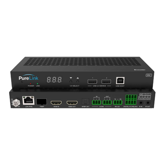
Page 7: Rear Panel - Encoder (Transmitter)
Can extract the audio from the HDMI input (PCM) b. Can output from the audio input of a single connected Decoder, both in Unicast mode only 9. RS-232 Transmitter and Receiver 10. Digital IO Relays 11. IR Receiver/Transmitter Input and Output VIP-400 USER MANUAL VERSION 1.5... -
Page 8: Front Panel - Decoder (Receiver)
Front Panel - DECODER (receiver) 1. Recessed Reset Switch 2. Power Green LED Indicator 3. Link Red LED Indicator 4. Three Digit Display 5. Channel Select Buttons 6. USB 2.0 7. USB Host VIP-400 USER MANUAL VERSION 1.5... -
Page 9: Rear Panel - Decoder (Receiver)
2. 1G LAN Port 3. 1G SFP Fiber Port 4. HDMI Out 5. SPDIF In 6. Stereo Input (unbalanced) 7. Stereo Output (Unbalanced) *Unicast mode only 8. RS-232 Tx/Rx 9. Digital IO Relays 10. IR Receiver Input/Output VIP-400 USER MANUAL VERSION 1.5... -
Page 10: Available Functions When Connected Over A Network
Data Rate (encoder) o Scaler output (decoder) o IP settings o Multicast/Unicast mode The VIP-400 employs a rich API, allowing settings, and diagnostics via the network. Please reference the separate VIP-400 API Command Reference for further information. VIP-400 USER MANUAL VERSION 1.5... -
Page 11: Building Your Av Over Ip Solution
Extension - Point to Point To use the VIP-400 as a point to point system, there is no need for a network, you can directly connect the ENCODER and DECODER by CAT or Fiber to create an extender solution. It is possible to create a... -
Page 12: Connecting To The Vip-400 Over The Network
Option 2: Via connection to a Decoder When connected by CAT or Fiber cable to a VIP-400 Decoder, and the Encoder and Decoder are set to the same Channel and no video input present at the Encoder, the VIP-400 Decoder will display the ‘Remote IP’... -
Page 13: Option 4: Advance Ip Scanner
IP Address and return to the Channel setting. Option 2: Via connection to a Display When connected a display, the Decoder will display the ‘Local IP’ in the lower right corner of the splashscreen. VIP-400 USER MANUAL VERSION 1.5... -
Page 14: How To Find All Ip Addresses Of A Vip-400 System
VIP-400 endpoints on the system. Option2: Using VPX Management Software VPX Management software allows for automatic detection of all VIP-400 devices on the network, as long as the software is on a Windows computer or VPX Commander that is in the same subnet. -
Page 15: Windows 8.1 And Windows 10 Computer Lan Port Setup
Option 2: Use the search window and type “Network and Sharing Center”. When the search function provides choices below, select Network and Sharing Center. The next page will be as shown below. Select the “Change Adapter Settings”. VIP-400 USER MANUAL VERSION 1.5... - Page 16 When you are in the Change Adapter Settings page as shown below, select the LAN adapter that you will use to communicate with the VIP-400system. For this example, we will select the middle listing, Qualcomm Atheros LAN Adapter. Double click on the listing. The properties page will open as shown below. VIP-400 USER MANUAL VERSION 1.5...
- Page 17 Note: Do not deselect the checkbox or change the selections of any other properties in the menu. When the window changes to the Properties page for the Internet Protocol Version 4, enter the same IP subnet as the VIP-400system. (VIP-400 default address is 169.254.nnn.nnn) VIP-400 USER MANUAL...
-
Page 18: Setting Up Your Mac Computer To Communicate On The Same Subnet
Setting up your Mac computer to communicate on the same subnet Opening Network Page From the top menu bar, you can either click on the network symbol Or click on the Apple icon in the upper left, and the select system preferences: VIP-400 USER MANUAL VERSION 1.5... - Page 19 Then select Network: Select the appropriate network adapter from the list in the left pane, and then set the correct IP subnet parameters. VIP-400 USER MANUAL VERSION 1.5...
-
Page 20: Network Switch Requirements
IGMP Snooping V2 and Jumbo Frame. We recommend the PureLink switch line as they are AV over IP purpose built and ready for use out of the box in closed systems. The PureLink line of network switches are all either L2+ or L3 switches depending on the model, and support CAT and Fiber transport. -
Page 21: Installation
Connections Power Each VIP-400 can be powered by PoE 802.3af via the RJ45 port, or from the included AC to 12Vdc power adapter. When multiple VIP-400s are present in a rack system, and are connected by fiber, or PoE is not an option, we recommend our RPS-1218, eighteen channel 12VDC UL listed power supply. -
Page 22: Passthrough - Follow Video
RS-232 connections default to a follow video mode. Passthrough – breakaway / layered switching Using the layered switching feature (Free Routing) of the VIP-400, you can break away the RS-232 and route it separately from the audio, video, USB, and IR layers. -
Page 23: Front Panel Button And Display Functionality
Press the up or down button to change the channel (0 <> 999) Reset to Factory defaults After confirming VIP-400 endpoint is powered up, press and hold the recessed Reset button until the Power and Link LED flash at the same time, then release the Reset button. -
Page 24: Warranty
TERMS & CONDITIONS PureLink shall repair or replace the Product if it develops a material fault during the period of warranty, on condition that i) the Product has only been subject to normal use in a domestic or commercial environment in a manner consistent with its... - Page 25 Most problems can be corrected over the phone through close cooperation between Customer and a PureLink technician. To better enable PureLink to address a warranty claim, please have the Product’s serial and model numbers. If PureLink, in its sole discretion, determines that an on-site visit or other remedial action is necessary, PureLink may send a representative to Customer’s site.
Need help?
Do you have a question about the VIP-400 and is the answer not in the manual?
Questions and answers