Table of Contents
Advertisement
Advertisement
Table of Contents

Related Manuals for Richmar ComboCare


Summary of Contents for Richmar ComboCare
- Page 1 ComboCare™ INSTRUCTION MANUAL...
- Page 2 This manual is valid for the ComboCare™ This user manual is published by Richmar. Richmar does not guarantee its contents and reserves the right to improve and amend it at any time without prior notice. Amendments may however be published in new editions of this manual.
-
Page 3: Table Of Contents
TABLE OF CONTENTS 1. GENERAL INFORMATION _______________________________4 1.1 General Description 1.2 Introduction to This Manual 1.3 Indication For Use 2. SAFETY INFORMATION _________________________________ 6 2.1 Warnings, Contraindications, Cautions, Adverse Reactions 3. PRESENTATION _______________________________________13 3.1 Panel for Front View 3.2 User Interface 4. -
Page 4: General Information
The ComboCare™ can provide electrical stimulation, ultrasound therapy or combination therapy. 1.2 Introduction to This Manual This manual has been written for the users of the ComboCare™. It contains general information on the operation, precautionary practices, and maintenance information. In order to maximize... -
Page 5: Indication For Use
1.3 Indications For Use Therapeutic Ultrasound Application of therapeutic deep heat for the treatment of selection sub-chronic and chronic medical conditions such as: Pain relief, muscle spasms and joint contractures. 2. Relief of pain, muscle spasms and joint contractures that may be associated with •... -
Page 6: Safety Information
2. IMPORTANT SAFETY INFORMATION Read instruction manual before operating. Be sure to comply with all “Contraindications”, Warnings”, “Cautions” and “Adverse reactions” in the manual. Failure to follow instructions may cause harm to user or device. The precautionary instructions found in this section and throughout this manual are indicated by specific symbols. - Page 7 5. DO NOT apply stimulation in the presence of electronic monitoring equipment (e. g., cardiac monitors, ECG alarms), which may not operate properly when the electrical stimulation device is in use; 6. DO NOT apply stimulation when the patient is in the bath or shower; 7.
- Page 8 Contraindications Therapeutic ultrasound should not be applied over the pregnant or potentially pregnant uterus. Therefore, therapeutic ultrasound should not be applied over the uterus unless specific assurance can be attained from the patient that she is not pregnant. 2. Patients who have cardiac pacemakers should be protected from direct ultrasound exposure over the thorax to protect the lead wires and pacer from such exposure.
- Page 9 CAUTIONS: For Therapeutic Ultrasound Ultrasound should not be applied in areas of reduced sensation or circulation. Patients having reduced sensation will not be able to notify the practitioner of discomfort if ultrasound intensities are too high. Patients with compromised circulation may have an excessive heat buildup in the treatment area.
- Page 10 11. Before each use, inspect the Ultrasound Applicator for cracks, which may allow the ingress of conductive fluid. 12. The ultrasound therapy controls unit is not designed to prevent the ingress of water or liquids. Ingress of water of liquids could cause malfunction of internal components or system and therefore create risk of injury to the patient.
- Page 11 ADVERSE REACTIONS: Skin irritation, inflammation, and electrode burns beneath the electrodes are potential adverse reactions. Patients may experience headache and other painful sensations during, or following the application of, electrical stimulation near the eyes and to the head and face. The clinician should stop using this device and should consult with the patient’s attending physician should the patient experience any adverse reactions from treatment used with this device.
- Page 12 Applicator Movement If movement of the applicator is too slow, the patient may feel periosteal pain characterized by a deep ache or pain. If motion is too fast, or if the applicator does not maintain good contact with the skin, the therapeutic effect of the sound waves will be reduced and the applicator may overheat.
-
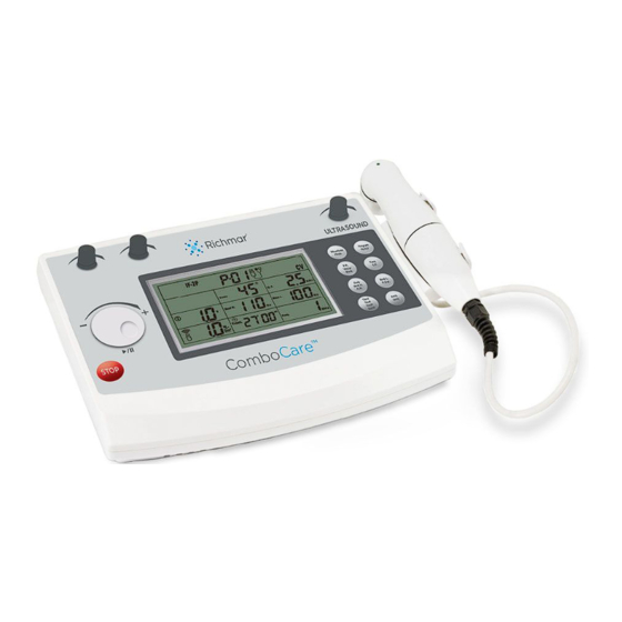
Page 13: Presentation
Treat. Freq. Cycle Duty Ramp STOP ComboCare ™ Select Channel 1 or adjust the output intensity of channel 1. Select Channel 2 or adjust the output intensity of channel 2. Central Controller Dial and Pause button. Stop treatment button. Power indicator. - Page 14 Button Remark Waveform Choose between therapeutic modes: Mode Electrical stimulation, Ultrasound thera- peutic or Combo therapeutic Waveform Mode Program Choose the therapeutic program, select CC —Constant Current output mode the [CC/CV] or switch program types Program CV—Constant voltage output mode (Common or professional) CC/CV F.M.—Frequency Modulation Vector...
-
Page 15: User Interface
3.2 User Interface Symbol Definitions IFC-Interferential Ultrasound output (Traditional 4 Pole) indicator IFC-Interferential Constant current (Traditional 2 Pole) control Electrical output Parameter channel indicator Electrical Time indicator Stimulation/ Ultrasound therapeutic/ Combination therapy Therapeutic program Constant Voltage control... -
Page 16: Installation
Remove the equipment and all accessories from shipping carton and gift- box. Visually check if there is any damage or missing parts or accessories. If yes, please report to local dealer or retailer where you purchase this unit. Your ComboCare™ equipment contains the following accessories. Part # Part... -
Page 17: Connection Of The Power Adapter
• The power adapter is a part of the supply circuit on which the device’s safety partly depends. The approvals for ComboCare™ are only valid if used in combination with this type of adapter. 4.2 Switching On Switch on the device, using ON/OFF switch [ ] 4.3 Switching Off and Disconnect Power Adapter... -
Page 18: Operation
5. OPERATION 5.1 Check Before Treatment • Ensure there are no contraindications to treatment. • Inspect the treatment area skin seriously for any abrasions, inflammation, surface veins etc. • Clean the skin of the treatment area with soap or alcohol (70%). •... - Page 19 After the electrodes no longer stick to the treatment site completely, dispose of electrodes and start with new electrodes. Replacement electrodes should be re-ordered through or on the advice of your physician to ensure proper quality. CAUTION: Before applying the self-adhesive electrodes, it is recommended to wash and degrease the skin, and then dry it.
- Page 20 5.1.4 Rubber Electrodes If used for delivery of electro-therapy, there are two conductive mediums for you to select, the first one is use electrode sponges as conductive mediums, another is use other conductive medium such as Transmission Gel. If using sponges, make sure the sponges are damp before putting electrodes into the sponges.
-
Page 21: Quick Set-Up For Electrical Stimulation
5.2 Quick Set-up for Electrical Stimulation 1. When you turn the ComboCare™ on, the device will get down to self-check about 10 seconds, and then the default parameters displayed are the last treatment mode. DO NOT turn device on with patient attached to the device as it could shock the patient during device self-check. - Page 22 7. This device has three working modes: a. Electrical Stimulation Only b. Ultrasound Only c. Combination Stim & Ultrasound Press [Waveform/Mode] button to select electrical stimulation mode. 8. There are 5 therapeutic waveforms for you to select. Rotate the Central controller dial to select waveform like Interferential, TENS, Russian, and EMS after you selected electrical stimulation therapeutic mode.
- Page 23 13. For safety using, load detection was designed in this device after the output intensity surpass 10.0mA/10.0V. If there are no electrodes stuck on patients’ skin, an alarm buzzer sound will appear and the intensity value will flash . 14. Press the [STOP] button to stop treatment of the current channel(s).
-
Page 24: Quick Set-Up For Combo Therapeutic (Ultrasound & Electrical)
2. Channel 1 will have no output. 2. Plug the cable into the corresponding output connector on ComboCare™. Connect the electrode to the Channel 2 connector on the back of the device. Channel 1 will remain open. - Page 25 6. Press [Waveform/Mode] button until [ ] indicator display on LCD. 7. There are 4 therapeutic waveforms that can be used for combo therapeutic. Rotate the Central controller dial to select waveform like Premodulated, TENS, Russian, and EMS. 8. Each waveform has 10 programs. Press the [Program/CC/CV] button to choose between Program P1-P10 by rotating the central controller dial...
- Page 26 11. Couple the applicator to the treatment area by keeping the entire surface of the applicator in contact with the gel that has been applied to the patient. Move applicator in a slow but continuous circular motion. This will ensure an efficient delivery of therapeutic ultrasound to the patient.
-
Page 27: The Default Parameters
16. To Pause treatment, first press CH2 knob and then press the central controller dial to pause the treatment. 5.4 The Default Parameters Each therapeutic waveform has 10 programs, you can set and save the parameters of all programs, the details about default parameters please refer to below: Waveform Pro-... - Page 28 Waveform Pro- Phase Vector Vector C.F. Beat Beat Ultra- Treat. gram (auto) (manual) (kHz) sound Time (°) (Hz) (Hz) (MHz, (min) 50%) Interferential Traditional (4 pole)
- Page 29 Waveform Pro- Phase C.F. Beat H. Beat L. Ultrasound Treat. Time gram (kHz) (Hz) (Hz) (MHz, 50%) (min) Premodulated Traditional (2 Pole)
- Page 30 μ Waveform Program Phase CC/CV Freq. (Hz) P. Dur. ( Ultrasound Treat. Time (MHz, 50%) (min) TENS...
- Page 31 μ Waveform Program Phase CC/CV Freq. (Hz) Ultrasound Treat. Time P. Dur. ( (MHz, 50%) (min)
- Page 32 Wave- Pro- Phase C.F. Freq. Duty Cycle Ramp Ultrasound Treat. form gram (kHz) (Hz) (s/s) (MHz, Time 50%) (min) Russian 10/10 10/10 10/10 4/12 4/12 4/12 4/12 4/12 4/12 10/10 10/10 10/10 10/10 10/10 10/10 10/10 10/10 10/10 10/10 10/10 10/10 10/10 10/10...
-
Page 33: Each Stimulation Set-Up Procedure
1. In order to turn on the device, press ON/ OFF switch to [ ] icon which is located on the side of the device 2. When you turn the ComboCare™ on, the device will perform a self-check for about 6~8 seconds, and then the default parameters will display the last treatment mode. - Page 34 7. Press the [Waveform] button to choose CC for constant current. 8. Press the [Vector] button, once to choose a manual vector degree. Press the [Vector] Vector button a second time to choose the auto F.M. Burst vector percentage (%) setting. Then rotate the Central controller knob ( ) to adjust to the desired setting.
- Page 35 14. To adjust the output intensity, press the corresponding channel being used for treatment and rotate the knob clockwise until a strong but comfortable stimulation is felt. The “STIM” symbol indicates when the device is giving the patient an active stimulation.
- Page 36 1. To turn on the device, press the ON/OFF switch to [ ] icon which is located on the side of the device. 2. When you turn the ComboCare™ on, the device will perform a self-check for about 6~8 seconds, and then the default parameters will display the last treatment mode.
- Page 37 7. Press the [Waveform] button to choose CC for Constant Current 8. Press the [Beat H.] button, and then rotate Beat H. the central controller dial ( ) to set the A.M. Duty parameter from (Beat. L) Hz to150Hz, 1Hz/step. 9.
- Page 38 15. To pause a channel, press the corresponding channel knob on the top of the device and then press the central controller dial to pause that channel. Each channel must be paused individually. 16. Press the [STOP] button to stop treatment of the current channel(s).
- Page 39 1. In order to turn on the device, please press ON/OFF switch to [ ] icon which is located on the side of the device. 2. When you turn the ComboCare™ on, the device will self-check for about 10 seconds, and then the default parameters will display the last treatment mode.
- Page 40 7. Press [F.M./Vector/Burst] button and then rotate the central controller dial ( ) Note: to set the F.M. PLUS Freq. (next setting) must be ≤ 250Hz. 8. Press [F.M./Vector/Burst] button and then rotate the Central controller dial to set the Burst rate from 0Hz to 10Hz, 1Hz/step.
- Page 41 14. Place the electrodes on or around the treatment area. You can choose to use one channel or two channels but must have at least two electrodes placed on the patient as shown in the figure to the left. Electrodes should be at least 2”...
- Page 42 1. To turn on the device, press the ON/OFF switch to [ ] icon which is located on the side of the device. 2. When you turn the ComboCare™ on, the device will perform a self-check for about 6~8 seconds, and then the default parameters will display the last treatment mode.
- Page 43 9. Press the [Freq.] button and then rotate Beat L. the central controller dial ( ) to set the P. Dur. frequency from 20Hz to100Hz, 5Hz/step. Freq. 10. Press the [Time] button, and then rotate Time the central controller dial ( ) to set the Cycle treatment time from 1min to 60min, 1min/step.
- Page 44 16. For safety purposes, the load detection function was designed so when the output intensity surpasses10.0mA/10.0V, and there are no electrodes placed on the patient’s skin or the device has not been connected to electrodes, an alarm buzzer will sound and the intensity value will flash and reset to zero.
- Page 45 5.5.5 Ultrasound Set-Up Procedure Select the Ultrasound Frequency: 1MHz or 3MHz Freq Up/Down Selection: Press button next to FREQUENCY to choose the desired frequency for treatment. CAUTION: When only one sound head is connected, the device will automatically detect which one is connect and the sound head that is not plugged in will show as not selectable on the treatment screen.
- Page 46 5.5.5.1 Start Treatment Place a generous amount of ultrasound gel on the treatment area. Place the ultrasound head on treatment area and move in slow circular motions while rotating the central controller dial to clockwise to slowly increase the intensity to a comfortable level to the patient. 5.5.5.2 Ultrasound Intensity The ultrasound intensity is adjusted with intensity control knob.
- Page 47 • If the LED light is solid green, there is good contact and the ultrasonic energy is being emitted. • If the treatment is paused or the sound head is not connected properly, there will be no green LED light on the top of the sound head. CAUTION: The movement performed with the sound head should be applied with regular movement, not too slow to avoid inducing heat, nor too fast to prevent...
- Page 48 The Treatment head A treatment head is a precision instrument. Great care is taken in the development and production in order to obtain the best possible beam characteristics. Rough treatment (jarring or dropping) can adversely affect these characteristics, and must therefore be avoided The Contact Medium In order to ensure efficient transfer of energy, a contact medium is required between the sound head and the body.
-
Page 49: Cleaning And Care
6. CLEANING AND CARE 6.1 Tips for Skin Care Follow these suggestions to avoid skin irritation, especially if you have sensitive skin: Clean the treatment area with mild soap and water. Rinse thoroughly and dry area completely before placing electrodes on or around the treatment area. -
Page 50: Cleaning The Lead Wires And Cables
4. Ensure electrode is completely dry before using the treatment. Check with patient to ensure the patient is not allergic to any cleaning solution used to clean the rubber electrodes, prior to administering treatment. 5. The sponge pads should be washed in warm water, using a household cleaner. -
Page 51: Troubleshooting
7. TROUBLESHOOTING For optimal use: Please follow the directions on the electrode packaging for the care of electrodes. The life of the electrodes varies, depending on skin conditions, skin preparation, storage and climate. Replace electrodes that no longer stick. NOTE: If the following measures fail to alleviate the problem, please call your dealer. - Page 52 “E1” or “E2” Hardware problem. Restart the device. displays on “E3” displays Detected the device is over The device will stop treatment on LCD temperature limit. automatically, please wait several minutes before using again. “E4” displays Detected the working current on LCD is over the limit.
-
Page 53: Specifications
8. SPECIFICATIONS 8.1 General Specifications: Adapter supply voltage 100V-240V, 47Hz-63Hz, 1.35A Adapter output 3A Max. Adapter Dimensions 3.5” (L) x 2.0” (W) x 1.15” (H) Dimensions 9.8” (L) x 7.3” (W) x 3.25” (H) Operating Environmental Temperature: 50°F (10°C) to 104°F (40°C), Relative humidity: 30%-85% Storage Environmental Temperature: -4°F (-20°C) to 131°F (55°C),... -
Page 54: Ultrasonic Generator Specifications
8.2 Ultrasonic Generator Specifications: Frequency (Freq.) 1MHz±10% 3MHz±10% Duty Factor (Duty) 10%-100%, Stepping 10% Pulse Repetition Rate 100Hz Treatment time Max. 30 minutes Output power 0.5W-10.0W, when duty factor>80% for 5cm2 0.5W-15.0W, when duty factor<70% for 5cm2 0.1W-2.0W, when duty factor>80% for 1cm2 0.1W-3.0W, when duty factor<70% for 1cm2 Effective radiating area (A 1. - Page 55 8.3.2 Interferential Traditional (2 Pole) Waveform Type Bi-phasic square Mode Selection CC (Constant Current) or CV (Constant Voltage) Carrier Frequency (C.F.) 2.5kHz Sweep High Beat Frequency (Beat H.) (Beat L.) - 150 Hz Sweep Low Beat Frequency (Beat L.) 1-(Beat H.) Hz Output Intensity 0-100mA (CC, at 1k ohm lead) 0-100 V (CV, at 1k ohm load)
-
Page 56: Storage
8.3.4 Russian Mode Waveform Type Bi-phasic square Mode Selection CC (Constant Current) or CV (Constant Voltage) Carrier Frequency (C.F.) 2.5kHz Burst Frequency (Freq.) 20-100Hz Output Intensity 0-100mA (CC, at 1k ohm lead) 0-100 V (CV, at 1k ohm load) Duty Cycle 10%, 20%, 30%, 40%, and 50% Treatment time 1-60 minutes... -
Page 57: Electromagnetic Compatibility (Emc) Tables
11. ELECTROMAGNETIC COMPATIBILITY (EMC) TABLES IMPORTANT INFORMATION REGARDING ELECTROMAGNETIC COMPATIBILITY (EMC) The device needs special precautions regarding electromagnetic compatibility (EMC) and needs to be installed and put into service according to the EMC information supplied in this manual. Care must be taken when operating this device adjacent to or stacked with other equipment. - Page 58 Guidance and manufacturer’s declaration - electromagnetic immunity The device is intended for use in the electromagnetic environment specified below. The customer or the user should assure that it is used in such an environment. Immunity test IEC 60601 test Compliance Electromagnetic level level...
- Page 59 Immunity IEC 60501 Compliance Electromagnetic environment guidance test test level level Conducted 3 Vrms 3 Vrms Portable and mobile RF Communications RF lEC 150 kHz equipment should be used no closer to any 61000-4-6 to 80 MHz part of the device, including cables, than the recommended separation distance Radiated 3 V/m80...
- Page 60 Recommended separation distances between portable and mobile RF communications equipment and the device. The device is intended for use in an electromagnetic environment in which radiated RF disturbances are controlled. The customer or the user of the device can help prevent electromagnetic interference by maintaining a minimum distance between portable and mobile RF communications equipment (transmitters) as recommended below, according to the maximum output power of the communications equipment...
-
Page 61: Glossary Of Symbols
12. GLOSSARY OF SYMBOLS Serial number Attention: Read the operating instruction before use! Equipment capable of delivering output values in excess of 10mA r.m.s. or 10V r.m.s. averaged over any period of 5s. Electrical devices are recyclable material and should not be disposed of with household waste after their useful life! Help us to protect the environment and save resources and take this device to the ap- propriate collection points. -
Page 62: Warranty
Richmar’s sole obligation in the case of any breach of its warranties set forth in the manual shall be, at Richmar’s option, to replace the Product with a new or factory certified refurbished product without charge to the purchaser or to refund the purchase price of the Product. - Page 63 4. The following is excluded under the warranty: a. All damage which has arisen due to improper treatment, e.g. nonobservance of the user instruction. b. Any device that has been opened or has a damaged warranty seal, automatically voids the warranty and no refund or warranty replacement will be provided.
- Page 67 Manufactured for: 3310.19.06.A ©2019 Compass Health Brands Corp.
Need help?
Do you have a question about the ComboCare and is the answer not in the manual?
Questions and answers