Table of Contents
Advertisement
Advertisement
Table of Contents

Related Manuals for Richmar Quattro 2.5


Summary of Contents for Richmar Quattro 2.5
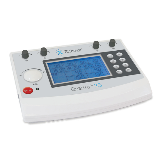
- Page 1 Quattro™ 2.5 INSTRUCTION MANUAL...
- Page 2 This manual is valid for the QUATTRO™ 2.5 This user manual is published by Richmar. Richmar does not guarantee its contents and reserves the right to improve and amend it at any time without prior notice. Amendments may however be published in new editions of this manual.
-
Page 3: Table Of Contents
TABLE OF CONTENTS 1. GENERAL INFORMATION _______________________________4 1.1 General Description 1.2 Indication for Use 2. SAFETY INFORMATION _________________________________5 2.1 Contraindications 2.2 Warnings, Cautions, Adverse Reactions 3. PRESENTATION _______________________________________10 3.1 Construction 3.2 User Interface 4. INSTALLATION _______________________________________13 4.1 Before Use 4.2 Connection of the Power Adapter 4.3 Switching On 4.4 Switch Off and Disconnecting Power Adapter 5. -
Page 4: General Information
1. GENERAL INFORMATION 1.1 General Description The microprocessor controlled Quattro™ 2.5 provides Interferential (4-pole interferential), Premodulated (2-pole interferential), medium frequency Russian (S and A), EMS (S and A) and TENS waveforms. You can choose between several different amplitude modulation options. The Interferential and Premodulated waveforms offer frequency modulation as well as a static frequency option. -
Page 5: Safety Information
2. SAFETY INFORMATION Read instruction manual before operating. Be sure to comply with all “Contraindications”, Warnings”, “Cautions” and “Adverse reactions” in the manual. Failure to follow instructions may cause harm to user or device. 2.1 Contraindications DO NOT use this device on patients who have a cardiac pacemaker, implanted defibrillator, or other implanted metallic or electronic device, because this may cause electric shock, burns, electrical interference, or death. - Page 6 4. Before administering any treatment to a patient you should become acquainted with the operating procedures for each mode of treatment available, as well as the indications, contraindications, warnings and precautions. Consult other resources for additional information regarding the application of electro-therapy. 5.
- Page 7 19. Patients with arterial or venous thrombosis or thrombophlebitis are at risk of developing embolisms when electrical stimulation is applied over or adjacent to the vessels containing the thrombus. If a patient has a history of deep vein thrombosis, even many years past, the affected area should not be stimulated.
- Page 8 8. Portable and mobile RF communications equipment can affect this device. DO NOT use a mobile phone or other device that emits electromagnetic fields, near the unit. This may result in incorrect operation of the device. 9. This device has been thoroughly tested and inspected to assure proper performance and operation! ADVERSE REACTIONS: Skin irritation, inflammation, and electrode burns beneath the...
- Page 9 PRECAUTIONS Federal law (USA) restricts this device to sale to or on the order of a physician. The long-term effects of chronic electrical stimulation are unknown. Electrical stimulation devices have no curative value. Electrical stimulation is not a substitute for pain medications and other pain management therapies.
-
Page 10: Presentation
3. PRESENTATION 3.1 Construction Waveform Step CC/CV Time Program Cycle Save Ramp Vector C.F. F.M. Freq. Burst Beat H. Beat L. A.M. F. Dur. Duty Freq. STOP Quattro ™ Channel 1 Knob • Press to enter treatment parameters for Channel 1 and 2. •... - Page 11 LCD display: Shows the current information of the device. Channel 3 Knob: • Press to enter treatment parameters for channel 3 and 4. • During treatment, press to display treatment parameters for channel 3 and 4 • Rotate to adjust the output intensity for channel 3 Channel 4 Knob: •...
-
Page 12: User Interface
3.2 User Interface Displays output intensity of channel 1; Displays total treatment steps of channels 1 and 2. Displays output intensity of channel 2; Displays treatment steps of channels 1 and 2. Displays output intensity of channel 3; Displays total treatment steps of channels 3 and 4. Displays output intensity of channel 4;... -
Page 13: Installation
4. Installation 4.1 Before Use Remove the equipment and all accessories from shipping carton and box. Visually check if there is any damage or missing parts or accessories. If yes, please report to local dealer or retailer where you purchase this unit. Your equipment contains the following Quattro™... -
Page 14: Connection Of The Power Adapter
4.2 Connection of the Power Adapter • Connect the power adapter to the device connector • Connect the power adapter to a wall socket CAUTION: Prior to connecting this device to the power supply, check that the voltage and frequency stated on the rating label match with the available power supply. -
Page 15: Operation
5. OPERATION 5.1 Check Before Treatment • Ensure there are no contraindications to treatment. • Inspect the skin treatment area for any abrasions, inflammation, surface veins etc. • Clean the skin treatment area with soap or alcohol (70%). • Shaving or clipping excessive hair on the skin treatment area can provide optimal treatment. - Page 16 5.1.3 Self-Adhesive Electrodes This device comes with 8 pieces 2”×2” and 8 pieces 2”×3.5” adhesive electrodes. You can select the appropriate sized electrodes according to the treatment area and output current density. It is recommended that manufacturer’s electrodes be used whenever possible to ensure the highest level of performance and contact with the treatment area and to give the most uniform delivery of the prescribed electro-therapy treatment.
- Page 17 5.1.4 Rubber Electrodes If used for delivery of electro-therapy, there are two conductive mediums for you to select from, the first one is to use electrode sponges as conductive mediums, and the other is to use a conductive medium such as an FDA approved Transmission Gel transmission gel is sold separately.
-
Page 18: Quick Set-Up For Electrical Stimulation
5.2 Quick Set-Up for Electrical Stimulation 1. In order to turn on the device, press ON/ OFF switch to [ ] icon which is located on the left side of the device 2. When you turn the Quattro™ 2.5 on, the device will perform a self-check for about 6~8 seconds, and then the default parameters will display the last treatment... - Page 19 8. There are 7 therapeutic waveforms for you to select. Press the [Waveform] button to choose the therapeutic waveform. Then rotate the central controller dial ( ) to select one of the following waveforms: IF-4P, IF-2P, EMS S, EMS A, TENS, Russian S and Russian A. 9.
- Page 20 13. Press the channel button ( 3 or 4 ) to enter channel 3 and 4 parameter setting mode if necessary. Then set the parameters following steps 8 through 12 above. 14. To pause a channel’s current, press the corresponding channel knob and then press the Central Dial to pause that channel.
-
Page 21: Using Preset Programs
5.3 Using Preset Programs Each therapeutic waveform has 10 programs with default parameters, but you can also set and save the parameters according to the patient’s need. The default parameters for each program are referenced below: IFC-4P & Premodulated IFC-2P Symptoms Pro- Vec-... - Page 22 TENS Symptoms Pro- Freq. Pulse A.M. Time gram Dur. Burst Acute Pain, 150 Hz 100% 20 min 250μ lg site Acute Pain, 150 Hz 100% 20 min 50μ sm site Chronic Pain, 10 Hz 100% 20 min 250μ lg site Chronic Pain, 10 Hz 100%...
- Page 23 EMS S/A Symptoms Freq. Pulse A.M. F.M. Con/ Ramp Time Pro- gram Dur. 250 μs EMS S: 30 Hz 100% 4/12 15 min Muscle Re- Ed, lg muscle group 50 μs EMS S: 30 Hz 100% 10/10 15 min Muscle Re-Ed, sm muscle group 150 μs...
- Page 24 RUSSIAN S/A Symptoms Pro- Freq. Duty Con/ Ramp Time gram RUSS S: Muscle 30 Hz 4/12 15 min Re-Ed, lg muscle group RUSS S: Muscle 30 Hz 4/12 15 min Re-Ed, sm muscle group RUSS S: Muscle 50 Hz 10/10 15 min Spasm Reduction RUSS S: Spasticity...
- Page 25 5.4 Each Stimulation Set-Up Procedure WARNING: When using IF-4P, you must use 2 channels (4 electrodes) and criss cross the channels as shown in the picture to the right. If using IF-2P, only use one channel (two electrodes). 5.4.1 4-Pole Interferential Stimulation Set-up Procedure 1.
- Page 26 7. Press the [Waveform] button to choose CC for constant current. 8. Press the [Vector] button, once to choose a manual vector degree. Press the [Vector] Vector button a second time to choose the auto F.M. Burst vector percentage (%) setting. Then rotate the Central controller knob ( ) to adjust to the desired setting.
- Page 27 14. To adjust the output intensity, press the corresponding channel being used for treatment and rotate the knob clockwise until a strong but comfortable stimulation is felt. The “STIM” symbol indicates when the device is giving the patient an active stimulation.
- Page 28 5.4.2 IF 2-P Interferential Stimulation Set Up Procedure 1. To turn on the device, press the ON/OFF switch to [ ] icon which is located on the side of the device. 2. When you turn the Quattro™ 2.5 on, the device will perform a self-check for about 6~8 seconds, and then the default parameters will display the last treatment mode.
- Page 29 7. Press the [Waveform] button to choose CC for Constant Current 8. Press the [Beat H.] button, and then rotate Beat H. the central controller dial ( ) to set the A.M. Duty parameter from (Beat. L) Hz to150Hz, 1Hz/step. 9.
- Page 30 15. If using Channels 3 & 4, press the knob to enter parameters by following steps 3-13 above. 16. To pause a channel, press the corresponding channel knob on the top of the device and then press the central controller dial to pause that channel. Each channel must be paused individually.
- Page 31 5. Press the [Program/Save] button to choose between P1-P10. Then rotate the Program Save central controller dial until the desired program number is displayed. 6. There are two modes in the device: Normal/Default Mode Professional Mode Step To switch from Normal to Professional, press and hold the [Step] button until you hear a “Beep”.
- Page 32 10. Press the [A.M.] button, then rotate the central controller dial ( ) to set the parameter from 0% to 100% (“A.M.” means amplitude modulation, the setting value indicates percentage of modulation, e.g.: Beat H. “0%” means no modulation, the intensity is A.M.
- Page 33 17. Adjust the output intensity and start treatment by rotating the output intensity adjustable knobs on the control panel. (0.5mA/step or 0.5V/step). The “STIM” symbol in the LCD indicates there is intensity output. Some waveforms have a pause in the middle of treatment and then it will start up again.
- Page 34 A.M. Waveform: Remark: EMS S (Synchronous) stimulation: For this treatment, use two channels (either channels 1 & 2 or 3 & 4). Electrodes for each channel will be placed on different muscle groups. During treatment, both channels will stimulate at the same time. Best used for Bi-lateral conditions.
- Page 35 5.4.4 TENS Stimulation Set-Up Procedure 1. To turn on the device, press the ON/OFF switch to [ ] icon which is located on the side of the device. 2. When you turn the Quattro™ 2.5 on, the device will perform a self-check for about 6~8 seconds, and then the default parameters will display the last treatment mode.
- Page 36 8. Press the [F.M.] button, and then rotate the central controller dial ( ) to set the F.M. Vector F.M. parameter from 0Hz to 249Hz,1Hz/step. But Burst F.M.+Freq.≤250Hz. 9. Press the [F.M.] button again to switch to Burst, and then rotate the central controller dial ( ) to set the Burst rate from 0Hz to 10Hz, 1Hz/step.
- Page 37 16. Place the electrodes on the patient. You will need to use at least one channel, with two electrodes. You can also use two channels with four electrodes as shown int he figure to the left. Place electrodes at least 2”...
- Page 38 5.4.5 Russian S/A Stimulation Set-up Procedure 1. To turn on the device, press the ON/OFF switch to [ ] icon which is located on the side of the device. 2. When you turn the Quattro™ 2.5 on, the device will perform a self-check for about 6~8 seconds, and then the default parameters will display the last treatment mode.
- Page 39 9. Press the [Freq.] button and then rotate Beat L. the central controller dial ( ) to set the P. Dur. frequency from 20Hz to100Hz, 5Hz/step. Freq. 10. Press the [Time] button, and then rotate Time the central controller dial ( ) to set the Cycle treatment time from 1min to 60min, 1min/step.
- Page 40 16. For safety purposes, the load detection function was designed so when the output intensity surpasses10.0mA/10.0V, and there are no electrodes placed on the patient’s skin or the device has not been connected to electrodes, an alarm buzzer will sound and the intensity value will flash and reset to zero.
-
Page 41: Specifications
6. SPECIFICATIONS 6.1 General Specifications: Adapter supply voltage 100V~240V, 50Hz~60Hz, 0.6A Adapter output 15V = 1.2A Max. Type of protection Class II Equipment against electric shock Adapter Dimensions 3.5” (L) x 2.0” (W) x 1.15” (H) Dimensions 9.8” (L) x 7.3” (W) x 3.25” (H) Operating Environmental Temperature: 50°F (10°C) to 104°F (40°C), Relative humidity: 30%-85%... - Page 42 6.2.2 2-Pole Interferential Mode Waveform Type Bi-phasic square Mode Selection CC (Constant Current) or CV (Constant Voltage) Carrier Frequency (C.F.) 4.0kHz Sweep High Beat Frequency (Beat H.) (Beat L.) - 150 Hz Sweep High Beat Frequency (Beat L.) 1 - (Beat H.) Hz Output Intensity 0-50mA (CC, at 1k ohm load) 0-50V (CV, at 1k ohm load)
- Page 43 6.2.4 EMS S/S mode Waveform Type Bi-phasic square Mode Selection CC (Constant Current) or CV (Constant Voltage) Frequency 1 - 250 Hz Frequency Modulation (F.M.) 0 - 249 Hz 30-400 µs Step Duration (P.Dur.) Amplitude Modulation (A.M.) 0%-100% Output Intensity 0-100mA (CC, at 1k ohm load) 0-100V (CV, at 1k ohm load) Treatment time...
-
Page 44: Cleaning And Care
7. CLEANING AND CARE 7.1 Tips for Skin Care Follow these suggestions to avoid skin irritation, especially if you have sensitive skin: Clean the treatment area with mild soap and water. Rinse thoroughly and dry area completely before placing electrodes on or around the treatment area. -
Page 45: Cleaning The Lead Wires And Cables
4. Ensure electrode is completely dry before using the treatment. Check with patient to ensure the patient is not allergic to any cleaning solution used to clean the rubber electrodes, prior to administering treatment. 5. The sponge pads should be washed in warm water, using a household cleaner. -
Page 46: Troubleshooting
8. TROUBLESHOOTING For optimal use: Please follow the directions on the electrode packaging for the care of electrodes. The life of the electrodes varies, depending on skin conditions, skin preparation, storage and climate. Replace electrodes that no longer stick. NOTE: If the following measures fail to alleviate the problem, please call your dealer. -
Page 47: Storage
“E1” or “E2” Hardware problem. Restart the device. displays on “E3” displays Detected the device is over The device will stop treatment on LCD temperature limit. automatically, please wait several minutes before using again. “E4” displays Detected the working current on LCD is over the limit. -
Page 48: Electromagnetic Compatibility (Emc) Tables
11. ELECTROMAGNETIC COMPATIBILITY (EMC) TABLES IMPORTANT INFORMATION REGARDING ELECTROMAGNETIC COMPATIBILITY (EMC) The device requires special precautions regarding electromagnetic compatibility (EMC) and needs to be installed and put into service according to the EMC information supplied in this manual. Care must be taken when operating this device adjacent to or stacked with other equipment. - Page 49 Guidance and manufacturer’s declaration - electromagnetic immunity The device is intended for use in the electromagnetic environment specified below. The customer or the user should assure that it is used in such an environment. Immunity test IEC 60601 test Compliance Electromagnetic level level...
- Page 50 Immunity IEC 60501 Compliance Electromagnetic environment guidance test test level level Conducted 3 Vrms 3 Vrms Portable and mobile RF Communications RF lEC 150 kHz equipment should be used no closer to any 61000-4-6 to 80 MHz part of the device, including cables, than the recommended separation distance Radiated 3 V/m80...
- Page 51 Recommended separation distances between portable and mobile RF communications equipment and the device. The device is intended for use in an electromagnetic environment in which radiated RF disturbances are controlled. The customer or the user of the device can help prevent electromagnetic interference by maintaining a minimum distance between portable and mobile RF communications equipment (transmitters) as recommended below, according to the maximum output power of the communications equipment...
-
Page 52: Glossary Of Symbols
12. GLOSSARY OF SYMBOLS Serial number Attention: Read the operating instruction before use! Equipment capable of delivering output values in excess of 10mA r.m.s. or 10V r.m.s. averaged over any period of 5s. Electrical devices are recyclable material and should not be disposed of with household waste after their useful life! Help us to protect the environment and save resources and take this device to the ap- propriate collection points. -
Page 53: Warranty
Richmar’s sole obligation in the case of any breach of its warranties set forth in the manual shall be, at Richmar’s option, to replace the Product with a new or factory certified refurbished product without charge to the purchaser or to refund the purchase price of the Product. - Page 54 4. The following is excluded under the warranty: a. All damage which has arisen due to improper treatment, e.g. nonobservance of the user instruction. b. Any device that has been opened or has a damaged warranty seal, automatically voids the warranty and no refund or warranty replacement will be provided.
- Page 55 Manufactured for: 3305.19.06.A ©2019 Compass Health Brands Corp.
Need help?
Do you have a question about the Quattro 2.5 and is the answer not in the manual?
Questions and answers