Table of Contents
Advertisement
Available languages
Available languages
Quick Links
USA office: Fontana
AUS office: Truganina GBR office: Ipswich
If you're having difficulty, our friendly
customer team is always here to help.
FRA office: Saint Vigor d'Ymonville
USA:cs.us@costway.com
AUS:cs.au@costway.com
GBR:cs.uk@costway.com
FRA:cs.fr @costway. com
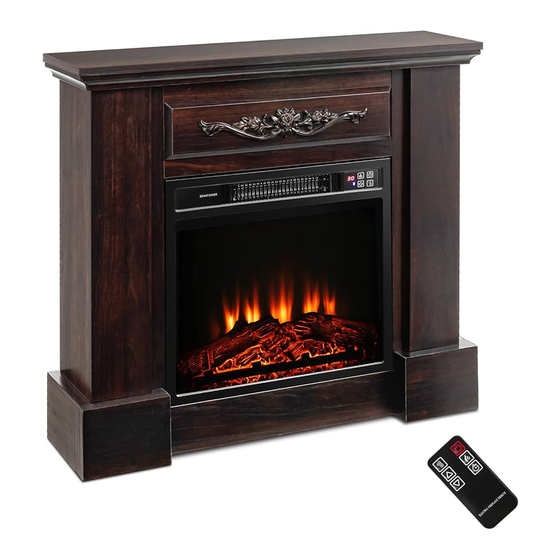
Electric Fireplace
Cheminée Électrique
FP10252
THIS INSTRUCTION BOOKLET CONTAINS IMPORTANT SAFETY INFORMATION. PLEASE READ AND KEEP FOR FUTURE REFERENCE.
Advertisement
Table of Contents

Subscribe to Our Youtube Channel
Related Manuals for Costway FP10252


Summary of Contents for Costway FP10252
- Page 1 AUS office: Truganina GBR office: Ipswich FRA office: Saint Vigor d'Ymonville USA:cs.us@costway.com If you're having difficulty, our friendly AUS:cs.au@costway.com GBR:cs.uk@costway.com customer team is always here to help. THIS INSTRUCTION BOOKLET CONTAINS IMPORTANT SAFETY INFORMATION. PLEASE READ AND KEEP FOR FUTURE REFERENCE. FRA:cs.fr @costway. com...
- Page 2 Before You Start Please read all instructions carefully. Retain instructions for future reference. Separate and count all parts and hardware. Read through each step carefully and follow the proper order. We recommend that, where possible, all items are assembled near to the area in which they will be placed in use, to avoid moving the product unnecessarily once assembled.
-
Page 3: Part Identification
PART IDENTIFICATION: Hardware Parts List: CODE DESCRIPTION CODE PICTURE DESCRIPTION Top Panel Bolt Front Up Panel Front Base Panel Plastic Connector Back Base Panel Metal Dowel Left Side Panel Right Side Panel Metal Cam L eft Front Panel Right Front Panel Wood Dowel Left Trim Panel Screw... - Page 4 Assembly Tools Required: Outils d'Assemblage Requis : OR / OU Hand Drill / Perceuse à main OR / OU Hex Key / Clé hexagonale...
-
Page 7: Important Safety Information
Safety Information IMPORTANT SAFETY INFORMATION PLEASE READ ALL OF THE INFORMATION IN THIS OPERATING MANUAL, INCLUDING ALL SAFETY, OPERATING, AND MAINTENANCE INFORMATION. TO AVOID THE POTENTIAL RISK OF FIRE, ELECTRIC SHOCK, OR INJURY TO PERSONS, USERS SHOULD FOLLOW THE DIRECTIONS AND WARNINGS IN THIS MANUAL. -
Page 8: Grounding Instructions
SAVE THESE INSTRUCTIONS CAUTION: When the heater is in use, the top center of the fireplace can get hot to the touch, and WARNING: There are no user serviceable parts inside may cause serious injury or burns. Always the fireplace/heater. If the unit appears to malfunction, turn the unit o ffand unplug the unit from the wall supervise small children around the fireplace/heater. -
Page 9: Pre-Installation
Part Description Quantity Screw 12 + 3 extra Grounding Pin Part Description Quantity Cover of Grounded Outlet Box Remote Control with Battery ireplace In sert op Trim ide Trim Adapter Grounding Lug Metal Screw Cover of Grounded Outlet Box Pre-installation ELECTRICAL SPECIFICATIONS Voltage: 120 VAC, 60 Hz Watts: 1400 Watts... -
Page 10: Fireplace Installation
Assembly Attaching the metal trims • Fasten the top trim (X) to the top of the fireplace insert (W) with two screws (18). Make sure that the right angle side points towards the front of the unit. • Align and attach two side trims (Y) to both sides of the fireplace insert (W) respectively with the right angle side facing the front of the unit, using two screws (18) per trim. - Page 11 Using the Control Panel Heater Control Button Main Power Button • Check that the heater outlet grill is not covered or obstructed in anyway, and make sure that the power to the unit is switched on. Flame Control Button Heater: UP Heater: Down Timer Button •...
-
Page 12: Informations De Sécurité Importantes
Informations de Sécurité WARNING: Do not use this fireplace insert if any part of it has been under water. Immediately call a qualified INFORMATIONS DE SÉCURITÉ IMPORTANTES service technician to inspect the firebox and replace any VEUILLEZ LIRE TOUTES LES INFORMATIONS DE CE MANUEL part of the electrical system which has been under water. -
Page 13: Instructions De Mise À La Terre
CONSERVEZ CES INSTRUCTIONS ATTENTION : Lorsque l'appareil de chauffage est AVERTISSEMENT utilisé, le centre supérieur du foyer peut devenir chaud au toucher et causer des blessures graves l'utilisateur à l'intérieur du foyer/appareil de chauffage. Si l'appareil semble mal fonctionner, éteignez-le et débranchez-le ou des brûlures. -
Page 14: Contenu Du Colis
Pièce Description Quantité 12 + 3 supplémentaires Broche de mise Pièce Description Quantité à la terre Couvercle de la Télécommande avec batterie boîte de sortie mise à la terre Insert de cheminée Garniture supérieure Adaptateur Garniture latérale Cosse de mise à la terre CONTENU DU COLIS Vis en métal Couvercle de la... - Page 15 Assemblage Fixer les garnitures métalliques • Fixez la garniture supérieure (X) au dessus de l'insert de cheminée (W) avec deux vis (18). Assurez-vous que le côté à angle droit pointe vers l'avant de l'appareil. • Alignez et fixez deux garnitures latérales (Y) aux deux côtés de l'insert de cheminée (W) respectivement avec le côté...
- Page 16 Utiliser le Panneau de Commande Bouton de Contrôle • Vérifiez que la grille de sortie du radiateur n'est pas couverte ou Bouton d'Alimentation Principal du Chauffage obstruée de quelque manière que ce soit et assurez-vous que Bouton de Contrôle de la Flamme Chauffage : HAUT l'alimentation de l'appareil est allumée.
-
Page 17: Entretien Et Maintenance
Entretien et Maintenance AVERTISSEMENT : Débranchez toujours l'alimentation électrique avant de nettoyer l'appareil de chauffage. Coupez d'abord l'alimentation principale. Retirez ensuite Return / Damage Claim Instructions la fiche électrique de la prise murale. DO NOT discard the box / original packaging. In case a return is required, the item must be returned in original box.
Need help?
Do you have a question about the FP10252 and is the answer not in the manual?
Questions and answers