Table of Contents
Advertisement
Available languages
Available languages
Quick Links
USA office: Fontana
AUS office: Truganina
GBR office: Ipswich
If you're having difficulty, our friendly
customer team is always here to help.
FRA office: Saint Vigor d'Ymonville
USA:cs.us@costway.com
AUS:cs.au@costway.com
GBR:cs.uk@costway.com
FRA:cs.f r @costway.com
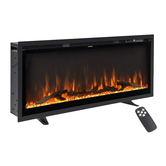
Electric Fireplace
Foyer Électrique
FP10530US
THIS INSTRUCTION BOOKLET CONTAINS IMPORTANT SAFETY INFORMATION. PLEASE READ AND KEEP FOR FUTURE REFERENCE.
Advertisement
Table of Contents

Related Manuals for Costway FP10530US


Summary of Contents for Costway FP10530US
- Page 1 GBR office: Ipswich FRA office: Saint Vigor d'Ymonville USA:cs.us@costway.com If you're having difficulty, our friendly AUS:cs.au@costway.com customer team is always here to help. GBR:cs.uk@costway.com THIS INSTRUCTION BOOKLET CONTAINS IMPORTANT SAFETY INFORMATION. PLEASE READ AND KEEP FOR FUTURE REFERENCE. FRA:cs.f r @costway.com...
-
Page 2: Consumer Safety Information
Before You Start Please read all instructions carefully. Retain instructions for future reference. Separate and count all parts and hardware. Read through each step carefully and follow the proper order. We recommend that, where possible, all items are assembled near to the area in CONSUMER SAFETY INFORMATION which they will be placed in use, to avoid moving the product unnecessarily once assembled. - Page 3 ● Extreme caution is necessary when any heater is used by or electric shock, or injury to persons. near children or invalids and whenever the heater is left ● ALWAYS plug heaters directly into a wall outlet/receptacle. operating and unattended. Never use with an extension cord or relocatable power tap ●...
- Page 4 ● ALWAYS store this heater in a dry location. NEVER use the ● The power cord supplied with the heater has a plug with two fireplace if it has become wet. flat blades (live and neutral) and one round pin (ground). If a 3-slot receptacle is not available, an adapter MUST be used.
-
Page 5: Parts & Hardware
PARTS & HARDWARE Specification and Dimensions A. Fireplace B. Wood Screws C. Wall Anchors D. 4x8mm Screws (x11) (x11) (x2) E. Wall Bracket F. Metal Bracket G. Remote Control (Fixed on back of firebox) H. Log Set I. Decorative J. Left Crystals Freestanding Leg K. -
Page 6: Product Dimensions
PRODUCT DIMENSIONS MANTEL Model 11.8"(300mm) Number 36" 17.7" 5.6" 34.7" 16.3" 12.2" 32.0" IF-36 91.44cm 45.0cm 14.2cm 88.3cm 41.5cm 30.9cm 81.3cm 42" 17.7" 5.6" 40.7" 16.3" 12.2" 38.0" IF-42 106.7cm 45.0cm 14.2cm 103.5cm 41.5cm 30.9cm 96.5cm 50" 17.7" 5.6" 48.7" 16.3"... - Page 7 RECESSED TO WALL INSTALLATION ( Tips: Wall bracket removing is NOT required. ) STEP 1. Select a dry wall to open a hole for fireplace box. Figure Figure (C) STEP 2. Remove two screws on both sides of the fireplace at front hole size corner.
- Page 8 Figure (G) Figure (E) ● Use the 4 screws (provided) to lock the STEP 4. Take the foam out of the fireplace. appliance into the wall Figure (E) with the existing two side flanges. Figure (G) STEP 5. Have two people to move the fireplace box to the wall hole or fireplace mantel.
-
Page 9: Wall Mounted Installation
Figure (I) Figure (a) STEP 7. Lock the front panel to the appliance with screws. Figure (I) WALL MOUNTED INSTALLATION Due to many different materials used on different walls, it is highly recommended that you consult your local builder before you install this appliance on the wall. - Page 10 Hook Bracket Hook Figure (c) Figure (e) STEP 6. Mark out the location, then mount the bracket (E) onto the wall using the supplied screws. This bracket MUST have the hooks STEP 4. Take the glass panel out of facing upward and be level. Figure (e) the fireplace box.
- Page 11 Free Standing Option Fasten the metal bracket (F) at the back of the fireplace with 2pcs of 4x8 mm screws, the other end to the wall with 1pc of ● Lay the heater on the floor or a table. drywall anchors. ●...
-
Page 12: Methods Of Operation
LOG-SET/CRYSTAL EMBER WARNING INSTALLATION Read and understand this entire owner’s manual, (Note: Please make the installation according to the embers which including all safety information, before plugging in or you bought or selected.) using this product. Failure do to so could result in electric shock, fire, serious injury, or death. - Page 13 ACTION & BUTTON FUNCTION INDICATION FLAME button: Makes 1. Press once. Flame Remote Control flame effect dimmer brightness effect gets and brighter. changing. NOTE: Flame effect 2. Press again. Until the stays on until the desired setting is power button is turned reached.
-
Page 14: Care And Maintenance
clogged with dust or lint. If there are, use a vacuum to clean the ACTION & BUTTON FUNCTION vent areas. INDICATION 4. With the POWER switch in the OFF position, plug the power TIMER button: Control 1. Press once. Indicator cord back into the outlet. -
Page 15: Troubleshooting
Metal: ● Electrical components are integrated in the fireplace and are not ● Buff using a soft cloth, slightly dampened with a citrus oil-based serviceable by the consumer. product. ● DO NOT use brass polish or household cleaners as these Storage: products will damage the metal trim. -
Page 16: Informations De Sécurité Importantes
POSSIBLE PROBLEM SOLUTION CAUSE Flame is not 1. Loose wiring. 1. Inspect wiring for loose moving. 2. Flame motor connections. defective. 2. Call a qualified service 3.Flame rod out of technician to replace flame place. motor. “3. Flame Rod” out of place due to rough transit/handing of the product. - Page 17 combustibles, tels que les meubles, les oreillers, la literie, les ● Pour éviter un éventuel incendie, NE bloquez PAS les prises papiers, les vêtements et les rideaux à au moins 3 pieds (0,9 d'air ou les sorties d'air de quelque manière que ce soit. Cela m) de l'avant de l'appareil de chauffage et éloignez-les des pourrait provoquer un incendie.
- Page 18 ● N'utilisez JAMAIS un support de montage mural d'un autre ii) Les appareils de chauffage consomment plus de courant fabricant. que les petits appareils. Une surchauffe peut se produire même si elle ne s'est pas produite lors de l'utilisation d'autres ●...
-
Page 19: Pièces & Accessoires
PRÉPARATION Ce produit comprend un panneau en VERRE ! Soyez toujours extrêmement prudent lorsque vous B. Vis à Bois (x11) C. Ancrages Muraux D. Vis 4x8mm (x2) manipulez le verre. Ne pas le faire pourrait entraîner (x11) des blessures ou des dommages matériels. Retirez toutes les pièces et la quincaillerie du carton et placez-les sur une surface propre, douce et sèche. -
Page 20: Dimensions Du Produit
Spécifications et Dimensions DIMENSIONS DU PRODUIT Numéro Modèle 36" 17,7" 5,6" 34,7" 16,3" 12,2" 32,0" IF-36 91,44cm 45,0cm 14,2cm 88,3cm 41,5cm 30,9cm 81,3cm 42" 17,7" 5,6" 40,7" 16,3" 12,2" 38,0" IF-42 106,7cm 45,0cm 14,2cm 103,5cm 41,5cm 30,9cm 96,5cm 50" 17,7" 5,6"... -
Page 21: Vue De Côté
INSTALLATION ENCASTRÉ AU MUR MANTEAU ( Conseils : Le retrait du support mural n'est PAS 11.8"(300mm) nécessaire. ) ÉTAPE 1. Sélectionnez un mur sec pour ouvrir un trou pour le boîtier du foyer. Figure (A) taille du trou VUE DE CÔTÉ Figure (A) Taille du Trou Découpé... - Page 22 Figure (C) Figure (E) ÉTAPE 2. Retirez les deux vis des ÉTAPE 4. Retirez la mousse du foyer. deux côtés du foyer au coin Figure (E) avant. Figure (C) ÉTAPE 5. Demandez à deux personnes de déplacer le boîtier du foyer vers le trou du mur ou le manteau du foyer.
-
Page 23: Montage Mural
Figure (G) Figure (I) ÉTAPE 6. Utilisez les 4 vis (fournies) pour verrouiller l'appareil dans ÉTAPE 8. Verrouillez le panneau avant le mur avec les deux à l'appareil avec des vis. Figure (I) brides latérales existantes. Figure (G) MONTAGE MURAL ÉTAPE 7. - Page 24 Figure (c) Figure (a) ÉTAPE 4. Retirez le panneau de verre du boîtier du foyer. Placez-le dans un endroit doux et propre. Figure (c) Figure (b) Figure (d) ÉTAPE 5. Retirez la mousse (A) du foyer. Figure (d)
- Page 25 Crochet Support Crochet Fixez le support métallique (F) à l'arrière du foyer avec 2 vis 4x8 mm, l'autre extrémité au mur avec 1 ancrage pour cloison sèche. Figure (e) ÉTAPE 6. Marquez l'emplacement, puis montez le support (E) sur le mur à l'aide des vis fournies. Ce support DOIT avoir les crochets vers le haut et être de niveau.
- Page 26 Option Debout Libre INSTALLATION DE L'ENSEMBLE DE BÛCHES/BRAISES EN CRISTAL ● Posez le radiateur sur le sol ou sur une table. ● Installez la base avec 6 vis (les vis sont au bas du foyer) comme (Remarque : Veuillez effectuer l'installation en fonction des braises fourni.
- Page 27 AVERTISSEMENT Lisez et comprenez l'intégralité de ce manuel du propriétaire, y compris toutes les informations de sécurité, Télécommande avant de brancher ou d'utiliser ce produit. Le non-respect de cette consigne peut entraîner un choc électrique, un incendie, des blessures graves ou la mort. ALIMENTATION Assurez-vous que l'interrupteur MARCHE/ARRÊT, situé...
- Page 28 ACTION & ACTION & BOUTON FONCTION BOUTON FONCTION INDICATION INDICATION Bouton de FLAMME : 1.Appuyez une fois. L'effet Bouton de 1.Appuyez une fois. Le Rend l'effet de de luminosité de la flamme TEMPÉRATURE : voyant s'allume. La flamme plus sombre change.
-
Page 29: Soin Et Entretien
SOIN ET ENTRETIEN Contrôle de Limitation de Température Cet appareil de chauffage est équipé d'un contrôle de limitation de Nettoyage température. Si le radiateur atteint une température dangereuse, il s'éteindra automatiquement. Pour réinitialiser : TOUJOURS éteindre le radiateur et débrancher le cordon d'alimentation de la prise avant de nettoyer, 1. -
Page 30: Dépannage
Dépannage Maintenance AVERTISSEMENT: DÉBRANCHEZ Risque de choc electrique ! NE PAS OUVRIR ! COMPLÈTEMENT L'APPAREIL ET LAISSEZ-LE Aucune pièce réparable par l'utilisateur à REFROIDIR AVANT TOUT ENTRETIEN. l'intérieur ! SEUL UN PERSONNEL DE SERVICE QUALIFIÉ TOUJOURS éteindre le radiateur et débrancher le DOIT ENTRETENIR ET RÉPARER CET APPAREIL cordon d'alimentation de la prise avant de nettoyer, ÉLECTRIQUE. - Page 31 CAUSE PROBLÈME SOLUTION POSSIBLE Ce problème peut être corrigé Return / Damage Claim Instructions aussi simplement que de retirer la vitre, de retourner le DO NOT discard the box / original packaging. foyer de haut en bas, de retirer In case a return is required, the item must be returned in original box. Without this un jeu de vis qui maintiennent your return will not be accepted.
Need help?
Do you have a question about the FP10530US and is the answer not in the manual?
Questions and answers