Table of Contents
Advertisement
Quick Links
AUBER INSTRUMENTS
Instruction Manual
Caution
This controller is designed for use under normal operating conditions within
the temperature range of 32°F to 122°F (0°C to 50°C) with a Relative
Humidity of less than 85%. Please refrain from exposing the controller to
water or rain, and avoid placing it under direct sunlight on hot days. When
not in use, store the controller in a cool and dry environment.
This controller comes with a one-year warranty, limited to the controller only.
1. Front Panel and Connection Ports
1. LCD display
2.SET ke y
3.TIMER/BACK ke y
4.Down key
5.Up k ey
12.Power adapter
conne ctor
11.Fan connector
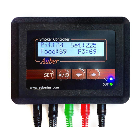
Figure 1. Front panel of a SYL-3615 controller.
Figure 2. Connection ports on the bottom of a SYL-3615.
2024.01
SYL-3615 Wi-Fi BBQ Controller
Firmware v1.1.86
Document version 1.0 (Jan, 2024)
Table 1. Recognizing Different Parts on a SYL-3615.
#
1
2
3
4
5
6
7
8
9
10
11
12
6. Wi-Fi indi cator
13
7. Output indicator
14
15
8. Pit probe
16
17
9. Food probe
10. Probe 3
Name
Description
LCD Display
Show probe readings and other information.
SET Key
* Short-press to access the cooking profile.
* Long-press to access menus.
TIMER / BACK
* Check status (step number, time, and output).
Key
* Cancel the Open-Lid function.
DOWN Key
* Mute the buzzer.
* Scroll down in the menu.
* Decrease the value.
UP Key
* Scroll up in the menu.
* Increase the value.
Wi-Fi Indicator
* Solid: connected to Wi-Fi and the server.
* Slow-blinking: lost connection.
* Fast-blinking: ready to pair (AP mode).
Output Indicator
Display the output status to the fan.
Pit Probe
The probe that measures the pit temperature.
Food Probe
A pointed probe can be inserted into food.
Probe 3
A third probe for monitoring food temperature.
Fan Connector
DC connector from the fan, 2.5 mm x 5.5 mm.
Power Adapter
DC connector, 2.1 mm x 5.5 mm. Supplies 12
Connector
VDC from the power adapter.
P1
Sensor port for the pit probe.
P2
Sensor port for the food probe.
P3
Sensor port for the third probe.
Output to Fan
Output port for the fan, 2.5 mm x 5.5 mm.
Power-In
Power input socket, 2.1 mm x 5.5 mm.
2. Getting Started
2.1 Powering Up the Device
Simply connect the 12 VDC power adapter to a wall outlet and then plug
the barrel connector (2.1 mm x 5.5 mm) to the power-in socket located
on the very left port at the bottom of the SYL-3615 controller (refer to
Figure 2).
The controller's LCD screen should illuminate and display its model
number and the firmware version (Figure 3a) for a few seconds.
Subsequently, the LCD screen will change to the normal display mode
(Figure 3b). The "-H-" is a sensor error code, which means no probe is
connected or detected.
Figure 3(a). The display screen when controller is just powered up.
WWW.AUBERINS.COM
SYL-3615
v1. 1. 86
P1/7
Advertisement
Table of Contents

Subscribe to Our Youtube Channel
Related Manuals for Auber Instruments SYL-3615


Summary of Contents for Auber Instruments SYL-3615
- Page 1 Simply connect the 12 VDC power adapter to a wall outlet and then plug the barrel connector (2.1 mm x 5.5 mm) to the power-in socket located on the very left port at the bottom of the SYL-3615 controller (refer to Figure 2).
- Page 2 4. Pairing a SYL-3615 to a Wi-Fi Router 2.2 Connecting Probes Important: The Wi-Fi module in SYL-3615 can only connect to a 2.4 GHz Wi-Fi network. Please make sure your router broadcast 2.4 GHz Wi-Fi Connect the pit probe to the P1 port, the food probe to the P2 port, and frequencies.
- Page 3 Figure 7. Change PRG to ON to enable the multi-step mode. Once you tap on the CONFIRM button, the SSID and password will be sent to the SYL-3615 so that it can log on to your 2.4 GHz Wi-Fi network.
- Page 4 AUBER INSTRUMENTS WWW.AUBERINS.COM (Back), BGE, Start WSM22, Save Back Save PID Settings WSM18, 4,5,6 (Back), BGE, Step x WSM22, Recall Back Recall PID Settings WSM18, 4,5,6 Determine the desired pit Back to the main temperature of this step Back menu How do you want to end this step? Ending? Note 1. Pit-AH is the high-limit alarm for the pit probe temperature. When the Cooking ...
- Page 5 AUBER INSTRUMENTS WWW.AUBERINS.COM Note 6. D is the Derivative Time, measured in seconds. The derivative action To recall a set of parameters and Control Mode, go to "Control Setting", use contributes to the output power based on the rate of temperature change. A the ▼...
- Page 6 Fan-Speed Control Mode. The default FMRV setting is parameter settings. Upon selecting “Yes” to Reset WiFi, the device will reboot, 4.0 V, a value recommended for blowers sold by Auber Instruments. Typically, and the blue LED indicator should start blinking rapidly, indicating that the there is no need to adjust this parameter when using the controller on an device is ready to pair with a mobile device.
- Page 7 While the open-lid detection might be triggered accidentally by a temperature drop unrelated to lid-opening during smoking, Figure 10. Two mounting hooks installed on the back of a SYL-3615 you can cancel this activation by pressing the TIME/BACK key on the controller.
Need help?
Do you have a question about the SYL-3615 and is the answer not in the manual?
Questions and answers