Advertisement
Quick Links
#38960 –
1/10/19
Overview
The Nitrogen Dioxide
(NO
with outstanding accuracy at low concentrations. The Duct unit (Part #NSB-NO2-D-BB) samples duct air using an
aspiration tube. The Rough Service unit features a ventilated BB box and is ideal for parking ramps, equipment rooms
.
and warehouses
The sensor has field selectable
ranges and outputs, plus two
independent SPDT alarm contacts
that switch at field selectable
concentrations. An alarm timer holds the
output relays on for a fixed time after the
NO
level has fallen below 80% of
2
setpoint. This allows additional fan run
time to be sure that the
NO
purged.
The LCD is backlit for 10 seconds
after a button push. A status LED
is green when the
NO
is below the
2
lowest relay setpoint. The LED turns red
when an alarm relay is on.
Specifications
Power
18 to 28 VAC, 7.2 VA Max
18 to 40 VDC, 180 mA Max
Field Selectable Ranges
0 to 2.5 ppm • 0 to 5.0 ppm
0 to 7.5 ppm • 0 to 10.0 ppm
Accuracy
±5% of full scale
Alarm Relays
2 Independent, Dry SPDT (Form C)
2 Amps at 24 VAC/DC, resistive
140 VA Inrush, 48 VA holding at 24 VAC
Field Wiring Terminals
Pluggable screw terminals, 14 to 24 AWG
Catalog No. 11-808-709-01
Nitrogen Dioxide Duct and Rough Service Sensor
)
Rough Service Sensor (Part #NSB-NO2-V-BB) offers enhanced electrochemical sensing
2
NO
2
NO
2
has been
2
Specifications subject to change without notice.
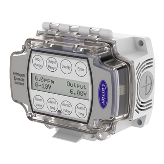
Figure 1: NO
Rough Service Sensor and parts
2
Response Time
<80 seconds from 10% to 90% of range
Alarm Relay Setpoints
1.0, 2.5, 5.0, 7.5, or 10 ppm
Alarm Timer
0, 1, 5, and 10 minutes
Field Selectable Analog Outputs
3-wire 4 to 20 mA
0 to 5 VDC, 1 to 5 VDC
0 to 10 VDC, 2 to 10 VDC
Environmental Operation Range
14 to 122°F (-10 to 50°C)
5 to 95% RH non-condensing
Sensor Module Life
7 years typical
Installation and Operation
Cover latch
screws
Conduit
Mounting
foam plug
screws
1 of 12
Advertisement

Related Manuals for Carrier NSB-NO2-V-BB


Summary of Contents for Carrier NSB-NO2-V-BB
- Page 1 Overview The Nitrogen Dioxide Rough Service Sensor (Part #NSB-NO2-V-BB) offers enhanced electrochemical sensing with outstanding accuracy at low concentrations. The Duct unit (Part #NSB-NO2-D-BB) samples duct air using an aspiration tube. The Rough Service unit features a ventilated BB box and is ideal for parking ramps, equipment rooms...
- Page 2 Nitrogen Dioxide Duct and Rough Service Sensor Installation and Operation #38960 – 1/10/19 Mounting Rough Service Ventilated Unit 1. Mount the unit on a solid, non-vibrating surface 3 to 5 feet above floor level. Mount in a horizontal orientation with the enclosure hinge at the top as shown in Figure 2.
- Page 3 Nitrogen Dioxide Duct and Rough Service Sensor Installation and Operation #38960 – 1/10/19 Mounting Holes Template Figure 4: Screw Hole Template. Shown actual size. Specifications subject to change without notice. Catalog No. 11-808-709-01 3 of 12...
- Page 4 A legend describing the function of each terminal is printed on the circuit card in the lid. (See Figure 5) Carrier recommends wiring the product with power disconnected. Proper supply voltage, polarity and wiring connections are important to a successful installation. Not observing these recommendations may damage the product and void the warranty.
- Page 5 Nitrogen Dioxide Duct and Rough Service Sensor Installation and Operation #38960 – 1/10/19 Relay Load Termination The Alarm Relays may be used to switch a load on or off. Figure 7 shows a circuit that may be used to switch on a load under alarm conditions.
- Page 6 Nitrogen Dioxide Duct and Rough Service Sensor Installation and Operation #38960 – 1/10/19 Relay Load Termination continued... Some circuits require a switched ground to operate, such as audible alarms, visual alarms, or large AC motor controllers. Figure 10 shows how to apply ground under an alarm condition. Figure 11 shows how to remove ground under an alarm condition.
- Page 7 Nitrogen Dioxide Duct and Rough Service Sensor Installation and Operation #38960 – 1/10/19 Operation continued... Display On and Display Off Modes measurement when the Display Mode is set to “On” . If the Display Mode is set The top line of the display shows the NO to “Off,”...
- Page 8 Nitrogen Dioxide Duct and Rough Service Sensor Installation and Operation #38960 – 1/10/19 Operation continued... Alarm Condition 1 Display If the NO measurement exceeds the Alarm 1 setpoint: • The NO measurement or the word “On” is displayed on the first line •...
- Page 9 Nitrogen Dioxide Duct and Rough Service Sensor Installation and Operation #38960 – 1/10/19 Reviewing Parameter Settings You can review the parameter settings at any time during normal operation by touching any of the eight buttons on the face of the unit. The following figures show a typical display when a button is touched. The values will display for 10 seconds and then the display will revert to normal.
- Page 10 Nitrogen Dioxide Duct and Rough Service Sensor Installation and Operation #38960 – 1/10/19 Parameter Setup and Default Settings If field personnel wish to change any parameter settings, they must remove the tamper resistant screws, open the cover, and press the switch on the board labeled “Setup”. Follow Figure 19 below to change parameters. Figure 19: Parameter Setup Flow Chart (Default settings are shown with gray shading)
- Page 11 Carrier recommends replacing the sensor module whenever the Replace Sensor alarm is active, every 7 years, or at the recalibration intervals required by the local jurisdiction. Replacement NO sensor modules (Part #NSB-NO2S) are available from Carrier.
- Page 12 Nitrogen Dioxide Duct and Rough Service Sensor Installation and Operation #38960 – 1/10/19 Diagnostics POSSIBLE PROBLEMS: POSSIBLE SOLUTIONS: Determine that the input is set up correctly in the controller’s and building automation General troubleshooting software. Check wiring for proper termination Check for corrosion at either the controller or the sensor.
Need help?
Do you have a question about the NSB-NO2-V-BB and is the answer not in the manual?
Questions and answers