Table of Contents
Advertisement
Quick Links
®
Mk 6 OIL MIST DETECTOR
INSTALLATION,
OPERATION AND
MAINTENANCE
MANUAL
1-59812-K001
PROPRIETY RIGHTS NOTICE
The information contained in this manual is the property of Carrier Fire & Security UK Ltd and may not be reproduced
or transmitted in any form or by any means, electronic, mechanical, photocopying, recording or otherwise, nor stored
in any retrieval system or any nature without the express written authority of Carrier Fire & Security UK Ltd.
© Copyright 2021 Carrier Fire & Security UK Ltd
Nov-21
Page i of xi
1-59812-K001 Rev 10
Advertisement
Table of Contents

Related Manuals for Carrier GRAVINER Mk 6


Summary of Contents for Carrier GRAVINER Mk 6
- Page 1 PROPRIETY RIGHTS NOTICE The information contained in this manual is the property of Carrier Fire & Security UK Ltd and may not be reproduced or transmitted in any form or by any means, electronic, mechanical, photocopying, recording or otherwise, nor stored in any retrieval system or any nature without the express written authority of Carrier Fire &...
-
Page 2: Table Of Contents
TABLE OF CONTENTS Chapter Page DESCRIPTION ......................12 INTRODUCTION DESCRIPTION TECHNICAL SPECIFICATION SYSTEM OVERVIEW INSTALLATION AND COMMISSIONING ..............21 CONTROL PANEL MOUNTING CONTROL PANEL CABLING JUNCTION BOX MOUNTING DETECTOR MOUNTING DETECTOR CABLES CONNECTING THE SYSTEM SYSTEM CHECKS PRIOR TO SWITCHING ON SYSTEM SETUP / CONFIGURATION COMMISSIONING THE SYSTEM OPERATION ........................64 SYSTEM POWER UP... - Page 3 DETECTOR CLEANING DECOMMISSIONING FAULT FINDING ......................92 FAULT INDICATIONS FAULT DIAGNOSTICS AND REMEDIES SPARE PARTS ......................112 CONTROL PANEL JUNCTION BOX DETECTOR SPARES KITS RECOMMENDED OPERATIONAL SPARES CABLE ASSEMBLIES AUXILARY OMD MK6 LOG READER Nov-21 Page iii of xi 1-59812-K001 Rev 10...
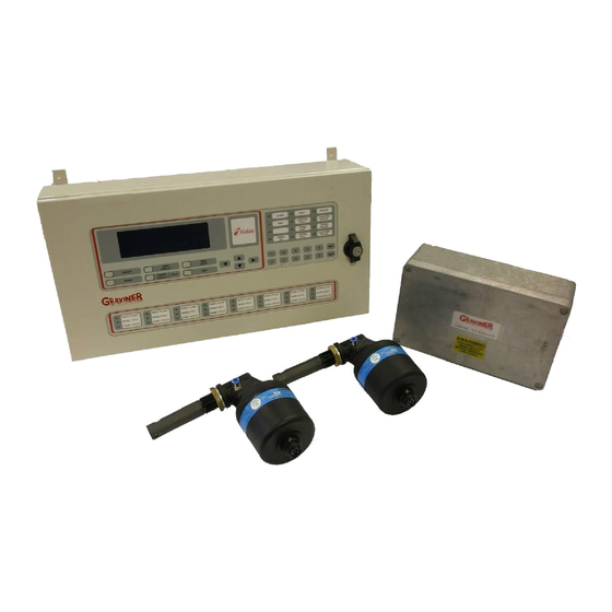
- Page 4 LI ST OF I LLUSTRATI ONS Figure Title Page Figure 1 Areas of Failure 2 Stroke Engine Figure 2 Areas of Failure 4 Stroke Engine Figure 3 Graviner Mk6 OMD Components Figure 4 Typical System Configuration Figure 5 MK6 Control Panel Bulkhead Mounting (1-53836-K170) Installation Drawing 21 Figure 6 MK6 Control Panel Flush Mounting (1-53836-K206) Installation Drawing Figure 7...
- Page 5 Figure 48 Clear Peak and Average Values Figure 49 Clear Maximum Average Values Figure 50 Confirm Clear Maximum Average Values Figure 51 System Status Menu Figure 52 Engine Status Selection Figure 53 Engine Status Figure 54 Set Alarm Levels Figure 55 Set Engine Average Alarm Figure 56 Detector Status Menu Figure 57 Detector Status Engine Selection...
- Page 6 Figure 87 Optics Test Figure 88 Alarm Test Engine Selection Figure 89 Alarm Test Engine Figure 90 Test Menu Engineer Level Figure 91 Shutdown / Slowdown Relay Test Engine Selection Figure 92 Shutdown / Slowdown Relay Test Figure 93 Event Log Menu Figure 94 Event Listing Figure 95 Event Log Select Event Type Figure 96 Event Log by Event...
- Page 7 Figure 124 Fuel in the lube oil Figure 125 Detector Base Cleaning Figure 126 Detector Assembly Figure 127 Cleaning Kit Figure 128 Pulling Tool Figure 129 Sample Chamber Cleaning Figure 130 Example Fault Screen Figure 131 Example Accepted Fault Screen Figure 132 Accepted Events Screen Figure 133 Event Text Figure 134 Backup Alarm Fault...
- Page 8 Figure 161 Junction Box Figure 162 Detector Spares Figure 163 Base Fixing Screw Removal Figure 164 Download Cable Connection Nov-21 Page viii of xi 1-59812-K001 Rev 10...
- Page 9 Figure 20 & 21 Graviner MK6 OMD System wiring colours Sept 17 Part number 1-21888-K073 added. Jan 18 Part number 1-43682-K037 changed to 1-43682-K261. Nov 20 UTC updated to Carrier Nov 21 Manual re-written. Nov-21 Page ix of xi 1-59812-K001 Rev 10...
- Page 10 OI L MI ST DETECTOR WARRANTI ES 1. Carrier Fire & Security UK Ltd (Carrier) warrants, for a period of 3 years from the handover of the new vessel which is installed with Graviner Mk6 Oil Mist Detector (OMD) system to the system owner, and...
- Page 11 6. The Warranties are conditional upon: a. the buyer or OMD system owner giving written notice to Carrier of the alleged defect, such notice to be given immediately when the buyer or OMD system owner discovers or ought to have discovered the defect;...
-
Page 12: Description
INTRODUCTION High temperatures, in excess of 200 C that occur on bearing surfaces under initial failure conditions, can lead to a rapid generation of oil vapour When the hot vapour contacts the relatively cooler atmosphere of the crankcase it condenses into a fine mist, with typical particle sizes of around 0.5 to 5 microns in diameter. -
Page 13: Description
The Graviner Mk 6 OMD provides the following benefits: • Multi engine capability, up to 8 engines on a single system • Suitable for both 2 stroke and 4 stroke engines. -
Page 14: Technical Specification
Each detector communicates electronically over a serial data link via the engine mounted Junction Box with the Control Panel designed to be mounted within the Engine Control Room. This eliminates the need to enter the machinery space in alarm conditions. Junction Box Auxillary Engine 5 Cylinder Backup alarm relay... - Page 15 Junction Box Enclosure Rating IP65 Max detector inputs Fuse Rating 4A 20mm slow blow Back-up alarm relay Volt-free change over contacts rated at 30Vdc 1A Power Consumption 100mW Temperature Rating Dimensions Height 186mm (110mm mounting centres) Width 318mm (240mm mounting centres) Depth 90mm Weight...
- Page 16 Height 309mm Width 559mm Depth 118.5mm Weight 8.7kg Nov-21 Page 16 of 132 59812-K001 Rev 10...
-
Page 17: System Overview
The Graviner MK6 OMD retains the long-established differential measuring system unique to Carrier Fire & Security Limited, which enables high sensitivity to be used while maintaining the maximum false alarm rejection. It still uses optical sensing, but light scatter instead of obscuration. - Page 18 On receipt of either an Average Alarm or Deviation Alarm the engine should, unless connected to a slowdown/shutdown relay, be stopped if safe to do so and allowed to cool down so that the background oil mist levels reduce before entering the engine room. When the oil mist levels have returned to normal then the Accept and Reset buttons can be operated from the Control Panel membrane and the system will then return to normal operation.
- Page 19 Membrane Keypad Function Keys Function Accept Acknowledge faults and alarms on the system. Silences the buzzer Reset Clears faults and alarms on the system. Faults and alarms must be accepted before the reset key will operate. Following reset the fault or alarm indication will be reactivated if the initial cause has not been corrected.
- Page 20 This process can be followed in section 2.8 of this manual. The Service level is also password protected (different from the Engineer Menu) and allows access to all functions. This is only available to authorised Carrier personnel and authorised Service Providers. Nov-21...
-
Page 21: Installation And Commissioning
CONTROL PANEL MOUNTING The Control Panel is designed for either bulkhead, 1-53836-K170 or flush, 1-53836-K206, mounting and must be installed in a control room or similar safe environment, not in the engine room. For bulkhead mounting fix the panel to a rigid structure using the four M6 mounting flanges at the rear of the unit. - Page 22 Figure 6 MK6 Control Panel Flush Mounting (1-53836-K206) Installation Drawing Nov-21 Page 22 of 132 59812-K001 Rev 10...
-
Page 23: Figure 7 Bezel - Part Number 1-35100-K187
Figure 7 Bezel - Part Number 1-35100-K187 Figure 8 MK6 Control Panel Flush Mounting Installation Drawing Cut Out Details Nov-21 Page 23 of 132 59812-K001 Rev 10... -
Page 24: Control Panel Cabling
CONTROL PANEL CABLING 24v DC I nput supply The Mk6 Control Panel should be powered from a floating 24v DC supply (+30% -25%) suitably rated depending on the number of detectors connected. PLEASE NOTE: - The Control Panel may not operate correctly if the external 24v power supply is referenced to the vessel earth and there is also a risk the input protection circuitry in the units could be damaged. - Page 25 the cable glands, the routing of the cables and to facilitate easy access to all aspects of the Junction Box. Each Junction Box can connect up to 14 Detectors, where 14 Detectors are not required the additional gland holes must be covered using 20mm metal blanking plugs, Lapp Kabel 52103125, to maintain EMC and IP integrity.
-
Page 26: Figure 9 Junction Box Installation
Figure 9 Junction Box Installation Nov-21 Page 26 of 132 59812-K001 Rev 10... -
Page 27: Detector Mounting
Figure 10 Junction Box External Connections DETECTOR MOUNTING Each detector is mounted to an individual crankcase via a ¾ inch BSP threaded hole. Ensure all detectors fitted to the engine are locked tightly in place by means of the lock nut supplied. It is recommended that the detector be located at the upper part of the crankcase wall where it is not in the direct line of the oil throw. -
Page 28: Figure 11 Ideal Mounting Position
Figure 11 Ideal Mounting Position The detector must be fitted at a maximum of plus or minus 20 degrees from the vertical. Horizontally the detector must be mounted level or with the detector body inclined towards the engine to ensure oil drainage. -
Page 29: Figure 12 Detector Head Installation
Figure 12 Detector Head Installation Nov-21 Page 29 of 132 59812-K001 Rev 10... -
Page 30: Figure 13 Detector Head Installation (Short Sample Pipe)
Figure 13 Detector Head Installation (Short Sample Pipe) Nov-21 Page 30 of 132 59812-K001 Rev 10... -
Page 31: Detector Cables
DETECTOR CABLES Each detector must be connected to the Junction Box by way of a supplied detector cable. Refer Figure 14. Ensure that the cables are run in a suitable cable tray and clipped at regular intervals to ensure they cannot be subjected to mechanical damage caused by vibration. -
Page 32: Figure 15 Detector Cable Assembly (Straight Connector)
Figure 15 Detector Cable Assembly (Straight Connector) Notes: Cable Spec 8-core screened (90 C) Halogen free & oil resistant. Cables should be secured every 0.5m (cable clips are not provided). Do not exceed the minimum bend radius as shown. Nov-21 Page 32 of 132 59812-K001 Rev 10... -
Page 33: Figure 16 Detector Cable Assembly (Right Angle Connector)
Figure 16 Detector Cable Assembly (Right Angle Connector) The pin to pin connections for the Detector cables are shown in the table below: Connector Pin Last Detector Colour of wire Function Function Pink Comms Out - TB10 EOL- White Comms In - C- in Yellow Comms In+... -
Page 34: Connecting The System
CONNECTING THE SYSTEM 2.6.1 Input power +24 V dc and 0 V dc power input cables for the Control Panel should be terminated onto Interface Board Supply Input (terminal block TB5). Where required by the vessel approval authority two separate 24v supply cables may be necessary. The two cables should be routed by different paths to reduce the risk of damage affecting both cables. -
Page 35: Figure 18 Power Cable Through Emc Gland
Cable gland Earthing Prongs Figure 18 Power cable through EMC gland Connect the earth wire to the earth stud, see Figure 19 Figure 19 Power Input Cable Earth Stud Connect the 24v and 0v in to TB5 on the Interface Board, 1-44782-K183, see Figure 19. Nov-21 Page 35 of 132 59812-K001 Rev 10... -
Page 36: Figure 20 Power Connections
Figure 20 Power connections The Control Panel should be connected from the earth stud to a suitable earthing point. Where permitted by the vessel approval authority only one power cable may be required. Connections can be made to either power input 1 or power input 2. Both the earth and the screen of the cable should be connected to earth at the 24v DC power supply. - Page 37 Feed the cable into the Control Panel via a metal IP65 EMC gland supplied, ensuring that the metal prongs make a good contact with the exposed cable screen as shown. The gland should be fixed in place using a toothed nut to cut through the Control Panel paint. The relays should be connected to the Alarm Monitoring System, AMS, to initiate the required response when the relay is activated.
- Page 38 Figure 22 Cable Gland Isolation Feed the cable into the Control Panel via a metal EMC gland, e.g. Lapp Kabel Skintop MS-SC-M-XL range, ensuring that the metal prongs make contact with the exposed cable screen as shown below Earthing prongs Figure 23 Cable Gland Isolation Remove a suitable knockout from the Control Panel and fix the cable glands in place using a toothed nut,...
- Page 39 Figure 24 Toothed Nut Connect the power cable in place at the Interface Board within the Control Panel. Figure 25 Power cable connections to Interface Board. Connect the Communications cable in place at the top of the Interface Board. Nov-21 Page 39 of 132 59812-K001 Rev 10...
- Page 40 Figure 26 Communications cable connections to Interface Board Junction Box Connections At the Junction Box strip the power supply cable to the required length for ease of installation. Approximately 100mm is usually suitable. For braided cables twist the cable screen to produce a tail. For foil screened cables use the drain wire.
- Page 41 Figure 28 Power cable Screen Tail Insulation. Feed the cables into the Junction Box via the two plastic glands. Connect the wires into the Junction Box Communications and Power Input terminals. Figure 29 Junction Box Power cable & Communications terminal connections.
- Page 42 2.6.4 Junction Box to Detector Connections At the Junction Box strip the Detector cables to the required length. The cables should be long enough to reach easily from the gland to the terminals. Remove approximately 1cm of the outer sheath to expose the cable screen as shown below Figure 30 Detector cable, stripped.
- Page 43 Connector Pin Last Detector Colour of wire Function Function Pink Comms Out - TB10 EOL- White Comms In - C- in Yellow Comms In+ C+ in Brown Comms Out + TB10 EOL+ Grey Backup Alarm Alarm Back-up Blue 0v supply 24v supply +24V Centre...
-
Page 44: Figure 34 Mk6 Junction Box Connections
Figure 34 MK6 Junction Box Connections Locate and tighten the collar of the connector to the top of the Detector. Figure 35 Connection to the Detector Head Assembly. Nov-21 Page 44 of 132 59812-K001 Rev 10... - Page 45 2.6.5 Backup relay connection in the Junction Box. The connection to the Backup Alarm relay can be made using a screened cable. The screen of the cable being terminated inside a metal EMC gland, e.g. Lapp Kabel Skintop MS-SC-M-XL range, ensuring that the metal prongs make contact with the cable screen. See Figure 21. Nov-21 Page 45 of 132 59812-K001 Rev 10...
-
Page 46: Figure 36 System Drawing
Figure 36 System Drawing Nov-21 Page 46 of 132 59812-K001 Rev 10... -
Page 47: Figure 37 Wiring Diagram
Figure 37 Wiring Diagram Nov-21 Page 47 of 132 59812-K001 Rev 10... -
Page 48: Figure 38 Wiring Diagram
Figure 38 Wiring Diagram 2.6.6 Cable screening It is critical that the cable screening instructions are followed. Failure to correctly connect the cable screens may result in communication failures and / or permanent damage to components. Note where armored cable is used the armor must not be used as the cable screen. Nov-21 Page 48 of 132 59812-K001 Rev 10... -
Page 49: System Checks Prior To Switching On
SYSTEM CHECKS PRIOR TO SWITCHING ON 2.7.1 Setting Detector Address Correct operation of the system depends on all Detector heads being correctly addressed. This is carried out after installation (refer to Figure 39). Figure 39 Detector Head 1-E3561-301 Remove the adhesive label covering the access port to the address switches. Use an instrument screwdriver to set the switches. - Page 50 etc. Ensure that the pink and brown wires from the last Detector are connected in to the EOL terminals in the Junction Box. 2.7.3 Ensure that the Communication and Junction Box power supply cables are connected correctly at the Junction Box (refer to section 2.6.3). 2.7.4 Check the cable run of the Communication and Junction Box power supply cables back from the Junction Box to the Control Panel to ensure that they are not damaged.
-
Page 51: System Setup / Configuration
SYSTEM SETUP / CONFIGURATION 2.8.1 Initial Actions and Settings 1. After switch on, the Control Panel display shows the message SCANNING FOR DETECTORS. Followed by a flashing COMMS FAULT message. The Detectors illuminate. 2. Press ACCEPT to silence the audible alarm. The COMMS FAULT continues to flash. Select MAIN MENU use the cursor to highlight ENGINEER. -
Page 52: Figure 43 Engine Configuration
2. In ENGINE/DETECTOR CONFIGURATION enter number of Engines. Press . Figure 43 Engine Configuration 3. Select each Engine in turn using the ▲ and ▼ navigation keys. 4. For each engine enter the number of Detectors. Press after each entry. Figure 44 Detector Configuration 5. -
Page 53: Figure 46 Entering Engine Description
2. Enter engine description letter by letter using the ▲/▼ keys to sequence through the alphabet and the ◄/► keys to move to the next letter Press store the name. Press ← to return to engine description page and select NEXT ENGINE. Figure 46 Entering Engine Description 3. -
Page 54: Figure 48 Clear Peak And Average Values
Figure 48 Clear Peak and Average Values Select YES and press 2. Clear the maximum average reading for each engine to ensure all test readings are erased. This can be done via MAIN MENU: ENGINEER 1. Configure System 7. Clr Max Average. Figure 49 Clear Maximum Average Values Select the required engine and press ... -
Page 55: Figure 52 Engine Status Selection
Figure 52 Engine Status Selection 3. Select the required Engine (1 2, 3, 4, etc) from the list. Figure 53 Engine Status 4. Read Maximum actual level value (retain this value for deviation alarm setting). 5. Set Average alarm level to twice the Maximum actual level, as follows: Return to the Configuration menu, Figure 42 select 3, Alarm Levels, Figure 54 Set Alarm Levels... -
Page 56: Figure 56 Detector Status Menu
2.8.7 Deviation Alarm Have the Maximum actual level for each engine to hand as used in setting the Average alarm level (from step 4. in section 2.8.6 above). Enter MAI N MENU and select ENGI NEER MAI N MENU. Enter the password, Press 1. -
Page 57: Commissioning The System
Dev. Alarm level = 2 x (Detector Peak Level minus engine Maximum actual level). 6. Repeat for each detector on each engine by using ← key to return to the required Detector Status screen. Note the required deviation alarm level in the range 0.05 to 0.5mg/l for each detector. -
Page 58: Figure 62 Test Menu User Level
2.9.2.1 Fault and Common Alarm relays 1. On the Control Panel press the Test key to access the Test Menu. The test menu can also be accessed from the Main Menu, Figure 40, by selecting 1. User 2. Test Figure 62 Test Menu User Level 2. -
Page 59: Figure 65 Test Menu Engineer Level
Figure 65 Test Menu Engineer Level 2. Select 8. Shutdown relay. Figure 66 Shutdown / Slowdown Relay Test Engine Selection 3. Select the engine to be tested from the list. Figure 67 Shutdown / Slowdown Relay Test 4. Select ACTI VATE or DE-ACTI VATE to change the relay state and ensure that the correct engine response is initiated by the AMS. - Page 60 2.9.4 Detector Smoke Alarm Test A smoke test should be performed on each detector to ensure that the correct response is obtained. One of two methods may be used to conduct the Smoke Alarm Test. Note: I solation of the Slowdown/Shutdown relays is required before commencing the smoke alarm test, see sections Error! Reference source not found.
-
Page 61: Figure 71 Clear Max Average Levels Engine Selection
Figure 70 Smoke Test 3. Dip the wick into the bottle of smoke oil and reseal the bottle firmly. Only a small quantity of oil is required. 4. Ignite the wick of the smoke tester and blow out the flame. Squeeze the pipette bulb to keep the wick smoking. -
Page 62: Figure 72 Clear Max Average Levels
Figure 72 Clear Max Average Levels Select Yes to confirm the levels are to be cleared. d. From the Configuration menu, Figure 42, select 8. Clr Peak & Avg Figure 73 Clear Peak and Average Levels e. Select Yes to confirm the levels are to be cleared. 8. - Page 63 To release the pipe from the connector, press in the metal collar on the end of the connector at the same time as pulling the pipe out Remove the nylon pipe from the pipe connector for stowage purposes. Refer to the Material Safety Data Sheet in the event of health or safety issues. Method 2 is recommended in situations where the use of a naked flame would be hazardous.
-
Page 64: Operation
Under normal operation the detector continuously monitors the oil mist level in the engine. The Control Panel communicates with each connected detector to obtain the measured oil mist level and the detector status. The Control Panel determines if the measured oil mist level is above the alarm levels or if there is a fault condition and activates the appropriate relays. -
Page 65: Engine Screen User
3.2.3 Service Level A 6-digit pin is required to access the Service Level. Service level access is reserved for Carrier approved Service Engineers. ENGINE SCREEN USER Information on a single engine can be accessed by pressing the Engine Display | Hold key. -
Page 66: Engine Status Information
Each of the engines may be examined using the up and down arrow keys to scroll through the available engines. ENGINE STATUS INFORMATION Engine status information may be accessed at User Level by selecting 1. System Status on the Main Menu: User screen. -
Page 67: Test Menu
The status screen shows: Average alarm level The Average Alarm Level set for that engine. Maximum actual level Shows the highest average oil mist level recorded on that engine since the maximum level was reset. Current Level The current highest oil mist level indicated by a detector on that engine. Slow down relay isolated Yes indicates the Slowdown / Shutdown relay for that engine is isolated. -
Page 68: Figure 84 Fault Relay Test
3.5.2 Fault Relay Allows the Fault Relay to be tested. 1. Select 2. Fault Relay Figure 84 Fault Relay Test 2. Select Enable or Disable to change the relay state and ensure that the correct engine response is initiated by the AMS. 3.5.3 System Test This is a legacy option and no longer performs a function. -
Page 69: Figure 86 Backup Alarm Test
3.5.5 Backup Alarm Tests the Backup Alarm signal between each detector and the Control Panel. Select 5. Backup Alarm A short beep maybe heard from the Control Panel buzzer while the connection from each detector is tested. Figure 86 Backup Alarm Test If the Backup Alarm test is completed successfully the display will return to the Test Menu. - Page 70 Figure 88 Alarm Test Engine Selection Select the required engine from the list. Figure 89 Alarm Test Engine Select the required detector from the list. The Control Panel and Detector will indicate an alarm condition on the selected detector. The Common Alarm Relay will be operated but not the Shutdown / Slowdown Relay.
-
Page 71: Event Log
Figure 92 Shutdown / Slowdown Relay Test 3. Select ACTI VATE or DE-ACTI VATE to change the relay state and ensure that the correct engine response is initiated by the AMS. EVENT LOG The Event Log enables the user to interrogate the past 256 events and can be accessed via the menus below. - Page 72 Figure 94 Event Listing The latest event held in the log will be displayed providing: The number of that event in the log together with the total number of events in the log. The even that occurred The events which occurred after a specified time and date. Additional events held in the log can be displayed using the up and down cursor keys.
-
Page 73: Detector Status User
Figure 98 Events Log from Time and Date Additional events held in the log can be displayed using the up and down cursor keys. 3.6.4 Download to PC With Engineer Level access an additional menu option is available allowing the Event Log contents to be downloaded to a PC. - Page 74 Figure 101 Detector Status Engine Selection Select the required engine from the list. Figure 102 Detector Status Detector Selection Select the required detector from the list Figure 103 Detector Status The status screen shows: The engine and detector being examined Peak level Shows the highest level recoded for that detector since the peak value was reset.
-
Page 75: Engineers Access
Figure 104 Detector Faults Engine Selection Select the required engine from the list Figure 105 Detector Faults Detector Selection Select the required detector from the list Figure 106 Detector Fault Status The status screen shows: The engine and detector being examined Fan fault Indicates if the detector fan has failed. -
Page 76: System Configuration Menu
System Status Provides status information on the current system operation, see section 3.10 Isolate Allows isolation of Detectors, Engines and Relays, see section 4.1 Test Accesses the Test Menu in Engineer Level, see section 3.5 Event Log Accesses the Event Log Menu in Engineer Level, see section 3.6 Cancel Password If the Engineers password has been altered Cancel Password reverts it to the default password. -
Page 77: Alarm Operation
Detector See section 3.7 Status Allows the panel Configuration to be reset to the default state. 3.10.1 Erase Configuration Select 3. Status Figure 110 Erase Configuration Select 1. Erase Configuration Figure 111 Confirm Configuration Reset. Confirm the configuration is to be erased. The panel configuration will revert to the factory default. Default Configuration Engines Detectors... - Page 78 Note: When the engine is started from cold in Arctic/Antarctic conditions, a water mist can be produced that could give a false alarm. All events are stored in the alarm/fault queue in order of occurrence. The user can scroll through the queue by use of the arrow keys.
-
Page 79: Backup Alarm
Following acceptance of the alarm the buzzer will silence and the common alarm relay is deactivated. Pressing reset will clear the alarm and return the Control Panel to the normal state. 3.12 BACKUP ALARM The Backup Alarm is a hard-wired link from each Detector installed on the system and operates independent of the system software. - Page 80 Slowdown/ Relay Unit off Unit on Fault Description Shutdown Engine Slow/Shutdown Alarm Common Alarm Fault Figure 113 Relay Function Modes Nov-21 Page 80 of 132 59812-K001 Rev 10...
-
Page 81: Maintenance
Warning: Do not work on the system unless the power is switched off or isolated. Caution: Ensure that anti-static handling procedures are observed applied when working on the system, i.e. Anti- Static Wrist Straps Warning: The I nvalidate Guarantee label around the Detector Head is fitted to ensure that the Detector head is not tampered with. - Page 82 4.1.1 Isolate Engine Select 1. Engine Figure 115 Isolate Engine Selection Select the required engine from the list. Figure 116 Isolate Engine Select ISO to isolate the engine, preventing the reporting of alarms or faults from all detectors on the LED.
-
Page 83: System Monitoring
Figure 119 Isolate Detector Select ISO to isolate the detector, preventing the reporting of alarms or faults. The Isolate and Detector Select DE-ISO to de-isolate the detector and return it to normal operation. 4.1.3 Isolate Relay Select 3. Relay Figure 120 Isolate Relay Engine Selection Select the required engine from the list. -
Page 84: Routine Maintenance Schedule
Event Log, see section 3.6. Examination of the event log could identify any underlying ongoing faults on the system, e.g. communications faults, memory errors etc. ROUTINE MAINTENANCE SCHEDULE This maintenance schedule is a guide only as every engine is different in its usage, oil, temperature, scrubber performance etc. - Page 85 3. Internally inspect the Mk6 Control Panel and Junction Box(s). 4. All Detectors installed on the engine(s) plus any Detector Heads which are considered as usable spares by the vessel (external view), document the status of the LEDs on each Detector. 5.
- Page 86 Figure 123 Emulsified oil in the detector base Fuel in the lube oil (a green colour in the lube oil) may indicate a problem with the fuel oil heaters or leaking valves. Figure 124 Fuel in the lube oil Metal particles may indicate wear due to high vibration levels.
-
Page 87: Detector Cleaning
ANNUAL: A Graviner Authorised Service Engineer should perform a complete system inspection. 1. Record serial numbers and software revisions for the Control Panel. 2. Verify all Graviner Mk6 System Functions. 3. Review and record Event log. 4. Clean Detector heads and Detector base Assemblies and renew base O-Rings. 5. - Page 88 Detector Head Detector Base Detector Sample Pipe Figure 126 Detector Assembly The oil mist detection chamber in each Detector Head must be inspected at regular intervals and cleaned to remove any build-up of oil splash or carbon deposits created by the operation of the engine. The OMD system will automatically warn the Users when the detection optics become partially obscured and must be cleaned.
- Page 89 To clean a detector: - 1. With the detector isolated disconnect the cable connector fitted to the top of the Detector Head. 2. Using a 4mm hexagonal key, loosen the two fixing screws in the Detector Base. The screws are self-retaining.
- Page 90 Figure 129 Sample Chamber Cleaning 11. Ensure that the glass ring around the side of the Detector Head and the small aperture shown in the image above are thoroughly cleaned with the foam cleaning buds. 12. To ensure thorough cleaning Graviner recommend that steps 10 and 11 are repeated with cleaning fluid applied to another foam bud.
-
Page 91: Decommissioning
18. If a fault is indicated for that Detector the Detector Head should be replaced, as it is approaching the end of its operational service life. 19. Repeat the above procedure for all Detectors cleaned. DECOMMISSIONING All the components of the Graviner Mk6 OMD system must be disposed of as electrical/electronic equipment waste. -
Page 92: Fault Finding
Warning: Do not work on the system unless the power is switched off or isolated. Caution: Ensure that anti-static handling procedures are observed applied when working on the system, i.e. Anti- Static Wrist Straps Prior to conducting fault diagnostics on the OMD system it is recommended to isolate the Slowdown/Shutdown Relays and the detectors being examined see section 4.1. - Page 93 Detector No fault indication. Control Panel Activation of the Fault Relay Buzzer on Fault LED flashing System Fault LED flashing Fault indicated on the LCD Further details on the type of fault indicated can be obtained by examining the event-log, see section 3.6 5.1.3 Accepted Faults To silence the Control Panel buzzer press the ACCEPT key.
- Page 94 5.1.4 Fault List A list of the fault messages that may be viewed in the Event Log are detailed below. Event Log Message Description Section Following a Backup Alarm Test the Control Panel failed to detect the activation of the backup alarm signal from a detector.
-
Page 95: Fault Diagnostics And Remedies
A list of the fault that are not listed in the Event Log are detailed below. Fault Description Section Continuous Backup A backup alarm is indicated without a deviation or 5.2.10 Alarm average alarm. Control Panel Reset The Control Panel is continuously resetting every 2 5.2.11 seconds. - Page 96 Figure 135 Link at Detector Connections If the buzzer sounds at the Control Panel while the link is in place, replace the detector cable. If the buzzer does not sound at the Control Panel while the link is in place, replace the Junction Box PCB.
- Page 97 5.2.1.3 All Detectors in fault If all the detectors connected to the Control Panel are shown with a Backup Alarm Fault the Control Panel Interface Board should be replaced. 5.2.2 Communications Fault Under normal operating conditions the Control Panel polls each of the detectors one at a time with the detector responding each time.
- Page 98 At the Control Panel disconnect the communications + and connections from the terminals. Using a multi-meter measure voltage between the two wires. The voltage measured should be between 200 300mV. If the voltage measured is not between 200 300mV go to 8. If the voltage measured is between 200 300mV replace the wires into the communications + terminals.
- Page 99 Figure 139 Loss of communications on consecutive detectors Having established which detectors are in fault it is necessary to establish the cause of the fault using the following steps. Remove the power from the system 2. Using a multi-meter measure the continuity between the c+ in (yellow), c+ out (brown) and between c- in (white), c- out (pink) terminals in the Junction Box for the detectors before and after the first detector with communications fault 3.
- Page 100 Reconnect each detector head one at a time ensuring the green LED is on. If the green LED is not on replace the detector. Reconnecting a failed detector may cause the Junction Box fuse to blow. Continue reconnecting the detectors until all are reconnected and powered. De-isolate all detectors on the engine.
- Page 101 5.2.3 Detector CPU Fault The detector continually checks the operation of the detector software to ensure that it has not been corrupted or locked up. If an error in the software operation occurs an automatic reset will be performed to restart the detector operation. If the software has been successfully restarted the performance of an automatic reset is indicated in the event log as a Detector CPU Fault.
- Page 102 Figure 142 Fan Fault An inspection of the engine event log, see section 3.6, will list the event: Fan Fault Eng X det Y 1. Using a 4mm hexagon key, unscrew 2 off screws from the underside of the Detector head. The screws are self-retaining.
- Page 103 Screw Removal Figure 144 Base Moulding Seal Caution: Do not press the fan, only handle the outer housing. 3. Using the Pulling Tool, Figure 145, remove the Fan Retaining Plug by capturing the shoulder and pulling. Carefully remove the Fan from its mountings, Figure 146. Figure 145 Pulling Tool One Fixing...
- Page 104 5. Remove the fixing screw holding the fan socket to the mounting plate and unplug the fan from the detector head. 6. Discard the failed fan and fit a replacement fan in reverse order of disassembly. 7. Reconnect the detector head to the base and to the Junction Box, ensure that the fault does not reoccur.
- Page 105 Accept and Reset the fault. If the PSU fault persists and be replaced. Control Panel Fitted with Interface Board, 1-44782-K085 Using a multi-meter measure the input power supply voltage at the Supply In terminals on the Interface Board. If the measured voltage is outside the limits 18 31.2v the power supply should be investigated. Inspect the Interface Board in the Control Panel.
- Page 106 With all Backup Alarm connections disconnected from the Interface Board and the buzzer sounding continuously, disconnect the ribbon cable between the Interface Board and the Main Control Processor Board. Ignore any faults indicated. If the buzzer continues to sound after pressing Accept replace the Main Control Processor Board.
- Page 107 If the voltage is within the limits replace the Main Control Processor Board. Remove the power from the system 10. Disconnect the power cable between the Interface board and Main Control Processor Board. 11. Check that the connector pins are clean and there is no oxidation. If necessary, lightly clean the pins with emery paper.
- Page 108 Figure 151 Soldered EEPROM On later versions the EEPROM (device IC17) is fitted in a socket (see below) and can be replaced without removing the Main Control Processor Board. Figure 152 Plug in EEPROM You will note from the image above that the EEPROM is now a smaller device and is supplied on a small daughter board which plugs into the existing socket on the Main Control Processor Board.
- Page 109 The original Control Panel display used a CCFL backlight that contained small amounts of mercury now prohibited by the RoHS directive. To comply with this directive Carrier have re-engineered the LCD and the display driver electronics on the Main Control Processor Board.
- Page 110 2. Unplug the cables from the Main Control Processor Board. 3. Remove the PCB fixing screws, 8 screws in total. 4. Remove the Main Control Processor Board. 5. The LCD must also be replaced if an old version is fitted. Figure 154 Control Panel Main Control Processor Board...
- Page 111 Figure 156 Unadjusted Display 11. Adjust the contrast on the Main Control Processor Board to produce a readable display. Figure 157 Contrast Adjustment 12. Re-program the original parameters for the system configuration and alarm levels. Nov-21 Page 111 of 132 59812-K001 Rev 10...
-
Page 112: Spare Parts
CONTROL PANEL Figure 158 Control Panel Door Nov-21 Page 112 of 132 59812-K001 Rev 10... - Page 113 TEST INSP TEST INSP Figure 159 Control Panel Box Control Panel Spares I tem Description Part No. Mk6 Main PCB 1-44782-K071-02 Mk6 LCD Display 1-43782-K120 Mk6 Status Display PCB 1-44782-K102-02 Function Key Membrane 1-39155-K047 Status Display Membrane 1-39155-K048 Mk6 8 Engine Status Display PCB 1-44782-K098-01 Door Seal 1-13455-D033...
- Page 114 6.1.1 Main Control Processor PCB Replacement 1. Prior to powering down the Mk6 OMD system use read and make note of the parameters below. These values will need to be re-entered into any replacement Main Control Processor PCB. a. The number of engines. b.
- Page 115 4. Remove the 4 fixing screws, washers and remove the PCB. 5. Fit the replacement PCB with the 4 fixing screws and washers. 6. Replace the Main Control Processor Board, re-fit all connectors. 7. Switch on system and allow it to initialis of the initialisation process.
- Page 116 3. Fit the firmware replacemen legs are in the socket. 4. Switch on system and allow it to initialise. 6.1.9 EEPROM Replacement Follow the steps detailed in section 5.2.12 6.1.10 Interface PCB Replacement Prior to replacing the Interface Board ensure the replacement board is the correct version, 1-44782- K183X where one input power supply connection is required or 1-44782-K183GL were two input power supply connections are required.
-
Page 117: Junction Box
JUNCTION BOX Figure 161 Junction Box Junction Box Spares I tem Description Part No. MK6 Junction Box PCB 1-44782-K184 4A 20mm Slow Blow Fuse 1-27411-K001 6.2.1 Junction Box PCB Replacement 1. Power down the system. 2. Disconnect all external wires from the Junction Box Board ensuring each wire is identified to allow correct reconnection to the replacement board. -
Page 118: Detector
DETECTOR Figure 162 Detector Spares Detector Spares I tem Description Part No. Mk6 Detector Head Replacement 1-D5622-001 Fan Assembly (1 Screw) 1-D5622-005-02 Fan Assembly (2 Screw) 1-53569-K005 Base Unit sub-Assembly 1-D5622-101 Base Unit sub Assembly (Short Sample 1-D5822-102 Pipe) Connector Push In 1-21888-K073 Base Moulding O Ring Seal 1-C1513-802... - Page 119 6.3.1 Detector Head replacement WARNI NG - Do NOT remove the Detector from the base whilst the engine is in operation. This action should be carried out whilst the engine is stopped to avoid the possibility of hot oil coming out of the Detector Base. 1.
-
Page 120: Spares Kits
3. Identify the cable to be removed at the Junction Box, disconnect each wire from the terminals. 4. Unscrew the top of the gland to release the cable strain release. 5. To prevent damage to the cable gland cut the cable near the top of the gland and pull the cable through the gland. -
Page 121: Recommended Operational Spares
RECOMMENDED OPERATIONAL SPARES Recommended Operational Spares Description Part No. Commissioning Kit 1-D9221-026 Service Kit 1-D9221-027 Interface Board 1-44782-K183X 1-44782-K183GL Main Processor Board 1-44782-K071-02 Switch Window Label 1-C9189-801 Cable, 25 metres 1-43682-K108-08 1-43682-K109-08 Detector Head Assembly 1-D5622-001 For systems with more than 10 detectors, it is recommended that additional detector head assemblies (1-D5622-001) are supplied. -
Page 122: Auxilary
Commissioning Kit 1-D9221-026 Service Kit 1-D9221-027 Smoke Oil 1-D9221-028 Smoke tester 1-D9221-029 AUXILARY The parts listed below are not supplied by Carrier and should be purchased locally. Manufactures Description Manufacture Supplier Supplier Stock No. Part No. RS Components 839-5340 Farnell... - Page 123 Nov-21 Page 123 of 132 59812-K001 Rev 10...
- Page 124 GRAVINER Mk6 OIL MIST DETECTOR SYSTEM WEEKLY PEAK READINGS Engine Name Detector Name Peak Peak Peak Peak Peak Peak Peak Peak Peak Peak Peak Peak Peak Peak Date Level Level Level Level Level Level Level Level Level Level Level Level Level Level Nov-21...
- Page 125 EXAMPLE SHEET Engine Name Main Engine Detector Name Peak Peak Peak Peak Peak Peak Peak Peak Peak Peak Peak Peak Peak Peak Date Level Level Level Level Level Level Level Level Level Level Level Level Level Level 01/03/21 08/03/21 Nov-21 Page 125 of 132 59812-K001 Rev 10...
- Page 126 Nov-21 Page 126 of 132 59812-K001 Rev 10...
- Page 127 Twice Yearly Maintenance See Section 4.2 for further details ☐ External Inspection Performed ☐ Internal Inspection Performed ☐ Detector sta ☐ Correct number of engines and detectors displayed on the Control Panel ☐ System component software versions documented ☐ Event Logs inspected and recorded ☐...
- Page 128 Annual Maintenance See Section 4.2 for further details ☐ System component serial numbers and software versions recorded ☐ System functions verified ☐ Event Logs inspected and recorded ☐ Detectors cleaned, status and parameter readings checked ☐ Detector bases inspected and cleaned ☐...
- Page 129 Nov-21 Page 129 of 132 59812-K001 Rev 10...
-
Page 130: Omd Mk6 Log Reader
PC, examined and saved. 6.8.1 Requirements PC running Windows Download cable, MT0021, available from Carrier USB to RS232 converter, if the PC does not have an integrated RS232 communications port (not supplied) OMD Log Reader software, P57972 6.8.2... - Page 131 Vessel Name Receive Log button Save Log button Comms port drop down Text window 6.8.3 Features Vessel Name Text box allowing the event log to be saved under the vessel name Receive Log button Clicking on the button will allow the programme to accept incoming data via the communications port Save Log button Save the contents of the text window as a text file...
- Page 132 6.8.4.2 Saving the event log To save the event log enter the vessel name in the Vessel Name text box Click on the Save Log button The log is saved as a text file in C:\vessel name\vessel name time date, e.g. C:\Seaham\Seaham 06_12 01_06.txt The text file can be read using any Windows©...
Need help?
Do you have a question about the GRAVINER Mk 6 and is the answer not in the manual?
Questions and answers