Table of Contents
Advertisement
Quick Links
#26268 –
02/28/2020
Overview
The Water Leak Detector is designed to sense the presence of water and alert a central monitoring system of the
potentially destructive situation. Upon water detection, an alarm relay changes state, and a local red LED illuminates.
The transmitter can be set for latching alarm or non-latching alarm with normally energized or de-energized operation.
An optional remote water sensor is available for small inaccessible locations such as AHU pans or under floor water
detection.
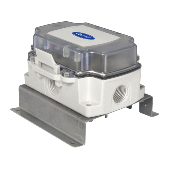
Figure 1:
Water Leak Detector with
Internal Sensor Probe
Part #NSB-LDT4-PS-BB
Catalog No. 11-808-639-01
Figure 2:
Water Leak Detector (above) with
Remote Spot Sensor (right) and
10 ft. FEP cable
Part #NSB-LDT4-RS10-BB
Water Leak Detector (above) with
Water Rope Sensor (below)
Part #s:
NSB-LDT4-RR10-BB (10 ft. rope)
NSB-LDT4-RR25-BB (25 ft. rope)
NSB-LDT4-RR50-BB (50 ft. rope)
NSB-LDT4-RR100-BB (100 ft. rope)
Specifications subject to change without notice.
Water Leak Detector
Installation and Troubleshooting
1 of 8
Advertisement
Table of Contents

Summary of Contents for Carrier NSB-LDT4-PS-BB
- Page 1 Part #s: Figure 1: NSB-LDT4-RR10-BB (10 ft. rope) NSB-LDT4-RR25-BB (25 ft. rope) Water Leak Detector with NSB-LDT4-RR50-BB (50 ft. rope) Internal Sensor Probe NSB-LDT4-RR100-BB (100 ft. rope) Part #NSB-LDT4-PS-BB Specifications subject to change without notice. Catalog No. 11-808-639-01 1 of 8...
- Page 2 Water Leak Detector Installation and Troubleshooting #26268 – 02/28/2020 Figure 3: Water Leak Detector with Built-in Sensor and a 5 Amp Relay in a System Diagram (Side View) Figure 4: Water Leak Detector with Remote Spot Sensor and a 5 Amp Relay in a System Diagram (Side View) Specifications subject to change without notice.
-
Page 3: Specifications
Water Leak Detector Installation and Troubleshooting #26268 – 02/28/2020 Specifications 24VAC +/- 10% Set Up Power Adjustable depth from .063” to 5 Amp Relays 4 VA max BB Sensor .84” (≈1/16th” default) Wiring Flex connector or liquid-tight fitting Adjustable depth from .063” to Relays Up to 6 wires Remote Sensor... - Page 4 Water Leak Detector Installation and Troubleshooting #26268 – 02/28/2020 Mounting Place the transmitter in a location where a water leak is likely to cause damage such as a cooling coil pan, a hot water tank pan, under a sink, under an elevated floor, or in a drop ceiling under pipes.
- Page 5 Water Leak Detector Installation and Troubleshooting #26268 – 02/28/2020 Rope Sensor Mounting Figure 11: Sub-floor Sensor Mounting The following combinations of sensors can be used: 1. Two rope sensors with a combined length of no Figure 10: Hot Water Tank Pan Mounting more than 100’.
-
Page 6: Wiring And Termination
Water Leak Detector Installation and Troubleshooting #26268 – 02/28/2020 Wiring and Termination Terminal Description Water Sensor (No polarity to water sensor cable) Water Sensor (No polarity to water sensor cable) NC2* Alarm Contact 2, Normally Closed to C2 when De-energized COM2 Alarm Contact 2, Common Alarm Contact 2, Normally Open to... -
Page 7: Set Up And Commissioning
Water Leak Detector Installation and Troubleshooting #26268 – 02/28/2020 Set Up and Commissioning Indication/Controls Description Red LED LED illuminates when water is detected Green LED LED illuminates when normal power is applied Reset Button Resets latching alarm contact (only if water is no longer present) Left side of J1 set to top two pins listed as “L”... -
Page 8: Maintenance
Water Leak Detector Installation and Troubleshooting #26268 – 02/28/2020 Maintenance Check the water sensor probe once a year to be sure there is no dirt or debris collected around the probes. Dirt or debris around the probes may cause nuisance alarms in moist situations. Change the service intervals depending on environmental conditions.


Need help?
Do you have a question about the NSB-LDT4-PS-BB and is the answer not in the manual?
Questions and answers