
Related Manuals for Akw T301


Summary of Contents for Akw T301
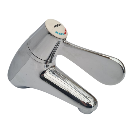
- Page 1 T301 Basin Mixer Valve Installation, Servicing & User Care Instructions Always read all the instructions carefully BEFORE installation and leave with the end user for future reference WRAS WR AS WRAS WRAS WRAS...
-
Page 2: High Pressure
OFF through COLD and WARM to a maximum blend temperature preset at 41°C, which can be adjusted if required. The T301 is designed for single or two hole basins. The supply connections are via flexible inlet tails which incorporate non return check valves and filters. - Page 3 The T301 is precision-engineered and should give continued superior and safe performance, provided that: 1. The T301 is installed, commissioned, operated and maintained in accordance with the recommendations given in this manual. 2. Periodic attention is given, as necessary, to maintain the product in good functional order Product Specifications 1.
- Page 4 The 15mm compression fitting adaptor allows connection to either flat-faced 1/2” BSP external or 15mm compression union. The hot supply connection is through the flexible inlet tail nearest the spout of the T301 tap, identified with a red mark. Note: Isolation valves must be fitted adjacent to the inlets.
-
Page 5: Installation
Before starting the installation of this product, ensure that the site conditions are suitable for installation of this product. The hot supply connection is through the flexible inlet tail nearest the spout of the T301 tap, identified with a red mark. - Page 6 2. Screw the fixing bolts fully into the T301 body. 3. Place the Rubber Washer (44mm od) in the groove in the base of the T301 body. 3. Screw the red flexible inlet tail into the T301 hole marked with a ‘RED DOT’...
- Page 7 Operation The T301 has a single lever that provides sequential operation from OFF through WARM to a maximum preset blending temperature. The maximum temperature is preset to approximately 41°C under ideal installation conditions at the factory. To change this setting refer to the information given in section: ‘Commissioning’.
- Page 8 Procedure Check that: a) the designation of the T301 mixing valve matches the intended application. b) the supply pressures are within the range of operating pressures for the designation of the valve. c) the supply temperatures are within the range permitted for the valve and by guidance information on the prevention of legionella etc.
- Page 9 The maximum blend temperature obtainable by the user should be limited to prevent accidental selection of a temperature that is too hot. The T301 tap is fully performance tested and the maximum temperature is preset to 41°C under ideal installation conditions at the factory. Site conditions and personal preference may dictate that the maximum temperature has to be reset following installation.
- Page 10 Commissioning Step 1 To Adjust Temperature Setting 1. Remove cover cap 2. Use a screwdriver to loosen the centre screw in the lever. 3. Move the lever to full hot, note its position and remove the lever. 4. Let the water run until the temperature stabilises.
- Page 11 In-Service Testing The purpose of in-service testing is to regularly monitor the thermal performance of the T301 mixing valve. Deterioration in performance can indicate the need for service work to be carried out on the system. If the authority concerned does not have a planned test and maintenance schedule then the suggestions below should form the basis of a new system.
- Page 12 No flow check supply. Filters are blocked - Check filters Isolation valve is closed - check valves. No hot water is reaching the T301 - check Water goes cold in use any boiler or water tank that is supplying hot water.
-
Page 13: Warranty Card
Warranty Card To be completed by the Installer (Product Identification can be found on the outer packaging) Warranty Model/Part Number ....................Serial Number (SN) ....................Batch number (BN) ....................Installation Date ....................Installed By ..................... Address ........................................................Contact ..................... - Page 14 ...°C Mains water supply running pressure (within range 0.5-10 bar) ..Bar With T301 turned on at max flow and max temperature setting, record the water temperature when it is stabilized ...°C Record details of test equipment (brand, model, serial number and calibration...
- Page 15 To be free of charge work must be only undertaken by AKW or our approved agents in the UK or the Republic of Ireland and with prior agreement.
- Page 16 These instructions are provided to advise the minimum standards of installation and recommends what is the best practice for the installation. Due to the very wide variability of possible installation conditions AKW cannot provide all circumstances for the installation. AKW cannot accept any liability in connection with this information or its use.
Need help?
Do you have a question about the T301 and is the answer not in the manual?
Questions and answers