Table of Contents
Advertisement
Advertisement
Chapters
Table of Contents
Troubleshooting

Related Manuals for StarCharge DH-AC0070XG70


Summary of Contents for StarCharge DH-AC0070XG70
- Page 1 7/11kW AC EVSE Installation & User Manual Wanbang Digital Energy Co., Ltd.
-
Page 2: Identifying Symbols
Identifying symbols Identifying symbols Symbols Meaning “Warning”, which indicates a hazard Pay attention to personal injuries or death caused by operation steps, practice or incorrect implementation. The operation after the "warning" sign can only be performed when the conditions are fully understood and satisfied. “Caution”, which indicates a hazard. -
Page 3: Table Of Contents
Content Content Identifying symbols ..........................1 Key Information ............................... 4 1.1 Safety Instruction ............................4 1.2 Specified Use ............................5 1.3 About this manual ............................. 5 Product Overview ............................6 2.1 Product Features ............................6 2.2 Product Functions ............................ 6 2.3 Technical Characteristics ......................... - Page 4 Content A.5 Product Installation ..........................24 A.5.1 Wall-mounted charger ........................25 A.5.2 Pole-mounted charger ........................30 B. Appendix................................. 34 Warranty Card ............................35 C.1 Warranty Terms and Conditions ......................35 C.2 Information Registration ........................36 Equipment Accessories ........................37 D.1 Equipment Accessories List ......................... 37 Instruction Manual Wanbang Digital Energy Co., Ltd.
-
Page 5: Key Information
Key Information 1. Key Information 1.1 Safety Instruction Symbol Content Failure to follow safety instructions can result in death, injury, and equipment damage. Refuse to bear any claims arising from this. Electrical hazard Only trained, qualified and authorized electrical professionals are responsible for installation. -
Page 6: Specified Use
Key Information Never use spray water to clean the charging point (Hose for garden watering, high pressure cleaners, etc) The adaptors or conversion adapters and extension cords are not allowed to be used. Cord extension sets are not allowed to be used. ... -
Page 7: Product Overview
Product Overview 2. Product Overview 2.1 Product Features Detailed description of product performance DH-AC0070XG70 DH-AC0110XG70 (Case C: plug, type2) (Case C: plug, type2) Model DH-AC0070XG71 DH-AC0110XG71 (Case B: socket, type2) (Case B: socket, type2) Rated Power 7 kW 11 kW Dimension 282 mm×409 mm×148 mm... -
Page 8: Technical Characteristics
Product Overview 2 ) The charger controller has the functions of measurement, control and protection for the charger. 3 ) With lighting protection, overload protection, short circuit protection, leakage protection, over voltage protection, under voltage protection and grounding detection. 4 ) Charger supports OCPP 1.6J communication protocol, and the charger can be linked to the data service platform and management platform (Cloud platform) of OCPP 1.6J. -
Page 9: Operation Instruction
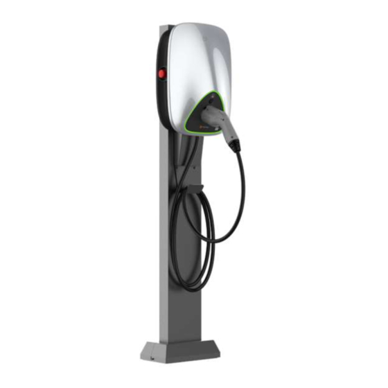
Operation Instruction 3. Operation Instruction 3.1 Appearance Introduction Case C Figure 3-3 Appearance of the wall-mounted (Subject to the actual product) [A]——Cable winding trough [B]——Emergency stop: press the button to stop the device running when the device is running abnormally press the button to unlock the charging ... - Page 10 Operation Instruction Figure 3-4 Appearance of the pole-mounted (Subject to the actual product) [A]——Optional cable winding trough [B]——Emergency stop: press the button to stop the device running when the device is running abnormally press the button to unlock the charging ...
-
Page 11: Storage Of Charging Cable And Connector
Operation Instruction 3.2 storage of charging cable and connector When charger is not used, the charging cable should be rolled up and put back into the cable winding trough in position [A] in figure 3-5 or placed on the bracket [I] of the stand as indicated in Figure 3-6,and the charging connector should be inserted into the designated position [F] for safe storage Wall Mounted Pole Mounted... -
Page 12: Start-Up Charger
Operation Instruction 3.3 Start-up charger Precondition The charging connector is not inserted in the vehicle. The charger is ready for operation (the LED status is constant green). The steps Step 1 Insert the charging connector into the vehicle and confirm that it is connected properly, the blue LED lights up means the charger is in connection status. -
Page 13: Indicator Description
Operation Instruction Stop Procedure 1) If the car is fully charged the charger will stop automatically. 2) To stop the charging manually, tap the RFID card or tap the “End Charging” on the Mobile App provided by the Charge Point Operator. 3) Unlock the charging cable from the vehicle. - Page 14 Operation Instruction deactivated from the system. A deactivated charger will not be able to be used for charging until it is reactivated on the charging management system by customer service engineer. Instruction Manual Wanbang Digital Energy Co., Ltd. Rev. B-004...
-
Page 15: Troubleshooting
Troubleshooting 4. Troubleshooting Fault Possible causes and solutions No power supply Power LED is off Damaged, please contact your service partners. Did not insert the connector into the vehicle properly: Pull out and plug in again. ... -
Page 16: Routine Maintenance
Routine Maintenance 5. Routine Maintenance The following routine maintenance items are for reference only. Please refer to the relevant standards and operation instructions for operation. 5.1 Power distribution system Power on and off steps of the distribution box. 1 ) Check if the supply voltage is normal. 2 )... -
Page 17: Auxiliary System
Routine Maintenance Complete inspection of all components and parts of the box. If any abnormality is found, please replace the parts as fast as possible. 5.4 Auxiliary System 5.4.1 Indicator Lights Monthly routine inspection: check if the indicator lights burning phenomenon are fixed firmly. ... -
Page 18: Maintenance Period
Routine Maintenance 5.7 Maintenance Period Every Every Every Inspection item Annual Treating method month quarter half year Charging connector √ √ √ √ Check Leakage switch √ √ √ √ Check protection Emergency stop √ √ √ √ Test function check Dust inspection of Check and √... -
Page 19: Customer Service
Record the model and serial number of the device and send to the contact information in 6.2 below. 6.2 Contact Information Company address: No.39, Longhui Road, Wujin High-tech zone, Changzhou, Jiangsu, China. Website: www.starcharge.com Company E-mail: starcharge@wanbangauto.com Hotline in China: 400-828-0768 Instruction Manual Wanbang Digital Energy Co., Ltd. Rev. B-004... -
Page 20: Installation Instruction
Installation Instruction A. Installation Instruction A.1 Installation Requirements The charger should not be installed close to dangerous locations such as water pipes, gas pipes, and steam pipes. The installation location should be convenient for charging. When laying the circuit, the wiring length should be shortened, and the cable resistance energy consumption should be reduced. - Page 21 Installation Instruction 11kW 400V Type B residual current protection device should comply with IEC 61008-1, IEC 61009-1, IEC 60947-2 and IEC 62423; The circuit breaker should comply with IEC 60898-1 or IEC 60947-2 or IEC 61009-1. Shunt release recommended model specifications are as follows: ...
- Page 22 Installation Instruction Figure A-1 7kW Installation electrical diagram Figure A-2 11kW Installation electrical diagram Instruction Manual Wanbang Digital Energy Co., Ltd. Rev. B-004...
- Page 23 Installation Instruction Figure A-3 Installation diagram detail The components in as below, Figure A-4 MCB Figure A-5 Type-B RCD Instruction Manual Wanbang Digital Energy Co., Ltd. Rev. B-004...
-
Page 24: Power Supply Requirements
Installation Instruction Figure A-6 Shunt release Figure A-7 Isolator switch A.2 Power Supply Requirements The power supply mode of the 7kW AC charger is AC single-phase power supply, and the input electrical requirements are showed as follow: AC working voltage: AC 230V ... -
Page 25: Environmental Requirements
Installation Instruction Voltage asymmetry: no more than 5% Voltage distortion rate: 10% of non-sinusoidal content does not exceed 10% of 400V A.3 Environmental Requirements Working environmental temperature: -30 ℃~﹢ 50 ℃ Relative humidity: 5% to 95% ... -
Page 26: Wall-Mounted Charger
Installation Instruction A.5.1 Wall-mounted charger The general assembly drawing is shown in Figure A-9. Figure A-9 General assembly drawing of wall-mounted charger Chargers use a same installation method between charger with charging cable (Case C) and with socket (Case B). ... - Page 27 Installation Instruction Figure A-10 Wall mounting height Figure A-11 Pole mounting height 2. As shown in Figure A-12, the center distance of the wall drilling hole, place the punching template at a suitable height, and mark the punching position on the wall with a pencil. Figure A-12 Wall drilling center distance 3.
- Page 28 Installation Instruction Figure A-13 Fixed Socket and Socket holder bracket 4. Thread the incoming cable through the large hole in the center of the rubber plug of the cable, compress the terminal, and fasten it to the wiring connector with a screw (torque 1.8 Nm, there is a wiring comparison table in the shell).
- Page 29 Installation Instruction Figure A-14 7kW wiring diagram 8. The 11kW charger is connected with 5 entry cables, as shown in Figure A-15. For 11kW chargers, please connect 5 entry cables Figure A-15 11W wiring diagram 9. Use 6 M4*12 screws to tighten the wiring compartment cover, and 2 M4*12 screws to tighten the crimping ferrule.
- Page 30 Installation Instruction If the entry cable is thick, please screw the crimping hoop in the above location. If the entry cable is thin (less than 14mm), please screw the crimping hoop in the below location. Figure A-16 Install the wiring cover and the cable entry clamp 10.
-
Page 31: Pole-Mounted Charger
Installation Instruction Wipe the insulation with an antistatic cloth. Do not use any corrosive solvents. Inspection Check that the base is secure and sealed. Check that the internal components of the device are securely fastened. Check that the electrical connections and wiring are correct and complete, that the connections are secure, and that the grounding is reliable. - Page 32 Installation Instruction Figure A-19 Into the line installation 2. After connecting the inlet line with the charging station body, fix the charging station body on the vertical column. First, use 2 cross M6*12 (torque: 1.8-2.0n.m) combination screws to fix the wall mount on the column. 3.
- Page 33 Installation Instruction Figure A -21 Thread hook and thread guard installation Fixed base 1. Drill 4 holes with A diameter of 10mm and A depth of 150mm on the concrete floor, and the spacing between hole centers is 100mm*200mm. Use 4 M10*120 expansion screws to install and tighten the charging station posts, as shown in Figure A-22 and A-23.
- Page 34 Installation Instruction Figure A-24 Install the rear decorative cover 3. Insert the front decorative cover into place from top to bottom and the back decorative cover, and fix both sides of the front decorative cover with 2 M4*12 flower-shaped composite screws (Torque: 1.4~1.6 N.M) with column core.
-
Page 35: Appendix
Appendix B. Appendix The following documents are the product design standards: IEC 61851-1:2017Electric vehicle conductive charging system –Part 1: General requirements IEC 61851-21-2:2018 Electric vehicle conductive charging system –Part 21-2: Electric vehicle requirements for conductive connection to an AC/DC supply – EMC requirements for off-board electric vehicle charging systems ... -
Page 36: Warranty Card
Warranty Card Warranty Card C.1 Warranty Terms and Conditions Basic information 1.Welcome to buy products for Wanbang Digital Energy Technology Co., LTD 2.If there are any requirements for the products purchased or used that exceed the standard warranty, please call 400-828-0768 to learn about various warranty upgrades and extended warranty services. ... -
Page 37: Information Registration
Warranty Card C.2 Information Registration Product name Product model Warranty period User name Contact Phone Contact address Dealer stamp Instruction Manual Wanbang Digital Energy Co., Ltd. Rev. B-004... -
Page 38: Equipment Accessories
Equipment Accessories D. Equipment Accessories D.1 Equipment Accessories List Equipment component Quantity Comments AC charger Pin terminal:E6012-BLACK,KST*3 Round terminal:RVL5-4,KST*3 Ground terminal:AVK16RD*1 Terminal connectors 11kW Pin terminal:E2508-BLUE,KST*5 Round terminal:RV3-4,KST*5 Ground terminal:AVK16RD*1 Wall hanging*1 M6 Self-tapping screws*4 Wall hanging 8mm diameter plastic expansion tube*4 M6 flower type pan head combination screw*2 RFID Card User manual... - Page 39 22 kW AC EV Charger Installation & User Manual Wanbang Digital Energy Co., Ltd.
-
Page 40: Identifying Symbols
Identifying symbols Identifying symbols Symbols Meaning “Warning”, which indicates a hazard Pay attention to personal injuries or death caused by operation steps, practice or incorrect implementation. The operation after the "warning" sign can only be performed when the conditions are fully understood and satisfied. “Caution”, which indicates a hazard. - Page 41 Content Content Identifying symbols ..........................1 Key Information ............................... 4 1.1 Safety Instruction ............................4 1.2 Specified Use ............................5 1.3 About this manual ............................. 5 Product Overview ............................6 2.1 Product Features ............................6 2.2 Product Functions ............................ 6 2.3 Technical Characteristics .........................
- Page 42 Content A.5 Product Installation ..........................24 A.5.1 Wall-mounted charger ........................25 A.5.2 Pole-mounted charger ........................29 B. Appendix................................. 34 Warranty Card ............................35 C.1 Warranty Terms and Conditions ......................35 C.2 Information Registration ........................36 Equipment Accessories ........................37 D.1 Equipment Accessories List ......................... 37 Instruction Manual Wanbang Digital Energy Co., Ltd.
-
Page 43: Key Information
Key Information 1. Key Information 1.1 Safety Instruction Symbol Content Failure to follow safety instructions can result in death, injury, and equipment damage. Refuse to bear any claims arising from this. Electrical hazard Only trained, qualified and authorized electrical professionals are responsible for installation. -
Page 44: Specified Use
Key Information Never use spray water to clean the charging point (Hose for garden watering, high pressure cleaners, etc) The adaptors or conversion adapters and extension cords are not allowed to be used. Cord extension sets are not allowed to be used. Specified Use ... -
Page 45: Product Overview
Product Overview 2. Product Overview 2.1 Product Features Detailed description of product performance DH-AC0220XG70 Model (Case C: plug, type2) Rated Power 22 kW Dimension 282 mm×409 mm×148 mm Cable Length Weight 5.6 kg Installation Wall-mounted , Pole-mounted Input Voltage: AC400±10% Input Mode :... -
Page 46: Technical Characteristics
Product Overview 3 ) With lighting protection, overload protection, short circuit protection, leakage protection, over voltage protection, under voltage protection and grounding detection. 4 ) Charger supports OCPP 1.6J communication protocol, and the charger can be linked to the data service platform and management platform (Cloud platform) of OCPP 1.6J. -
Page 47: Operation Instruction
Operation Instruction 3. Operation Instruction 3.1 Appearance Introduction Case C Charger Figure 3-1 Appearance of the wall-mounted (Subject to the actual product) [A]——Cable winding trough [B]——Emergency stop: press the button to stop the device running when the device is running abnormally ... - Page 48 Operation Instruction Pole-mounted charger Figure 3-2 Appearance of the pole-mounted (Subject to the actual product) [A]——Optional cable winding trough [B]——Emergency stop: press the button to stop the device running when the device is running abnormally [C]——Charge plug unlock button: press the button to unlock the charging plug ...
-
Page 49: Storage Of Charging Cable And Connector
Operation Instruction 3.2 storage of charging cable and connector When charger is not used, the charging cable should be rolled up and put back into the cable winding trough in position [A] in figure 3-5 or placed on the bracket [I] of the stand as indicated in Figure 3-6,and the charging connector should be inserted into the designated position [F] for safe storage Wall Mounted Pole Mounted... -
Page 50: Start-Up Charger
Operation Instruction 3.3 Start-up charger Precondition The charging connector is not inserted in the vehicle. The charger is ready for operation (the LED status is constant green). The steps Step 1 Insert the charging connector into the vehicle and confirm that it is connected properly, the blue LED lights up means the charger is in connection status. -
Page 51: Instructions To User
Operation Instruction 3.5 Instructions to User The below instructions and safety precautions shall be installed and placed right beside the charging station by the Charge Point Operator in a manner that is sturdy and visible to the user. Basic Instructions to use the Charger: Start Procedure 1) Check if the power is “ON”... -
Page 52: Emergency Button
Operation Instruction Standby Green Constant Charging Blue Changes gradually Fault Constant Vehicle end S2 Blue Pulsate (1Hz) disconnect Charging current < Blue Constant 1A for 10 minutes 3.7 Emergency button In the event of an emergency, the user should depress the emergency stop button on the charger. Once activated, the emergency stop button will cut off the power supply of the charger from the relay coil and disconnect the hardware circuit board. -
Page 53: Troubleshooting
Troubleshooting 4. Troubleshooting Fault Possible causes and solutions No power supply Power LED is off Damaged, please contact your service partners. Did not insert the connector into the vehicle properly: Pull out and plug in again. Did not execute charging steps correctly: ... -
Page 54: Routine Maintenance
Routine Maintenance 5. Routine Maintenance The following routine maintenance items are for reference only. Please refer to the relevant standards and operation instructions for operation. 5.1 Power distribution system Power on and off steps of the distribution box. 1 ) Check if the supply voltage is normal. 2 )... -
Page 55: Auxiliary System
Routine Maintenance Complete inspection of all components and parts of the box. If any abnormality is found, please replace the parts as fast as possible. 5.4 Auxiliary System 5.4.1 Indicator Lights Monthly routine inspection: check if the indicator lights burning phenomenon are fixed firmly. ... -
Page 56: Maintenance Period
Routine Maintenance 5.7 Maintenance Period Every Every Every Inspection item Annual Treating method month quarter half year Charging connector √ √ √ √ Check Leakage switch √ √ √ √ Check protection Emergency stop √ √ √ √ Test function check Dust inspection of Check and √... -
Page 57: Customer Service
Record the model and serial number of the device 6.2 Contact information. 6.2 Contact Information Company address: No.39, Longhui Road, Wujin High-tech zone, Changzhou, Jiangsu, China. Website: www.starcharge.com Company E-mail: starcharge@wanbangauto.com Hotline in China: 400-828-0768 Instruction Manual Wanbang Digital Energy Co., Ltd. -
Page 58: Installation Instruction
Customer Service A. Installation Instruction A.1 Installation Requirements The charger should not be installed close to dangerous locations such as water pipes, gas pipes, and steam pipes. The installation location should be convenient for charging. When laying the circuit, the wiring length should be shortened, and the cable resistance energy consumption should be reduced. - Page 59 Routine Maintenance Type B residual current protection device should comply with IEC 61008-1, IEC 61009-1, IEC 60947-2 and IEC 62423. The circuit breaker should comply with IEC 60898-1 or IEC 60947-2 or IEC 61009-1. Shunt release recommended model specifications are as follows Brand Model A9A26476...
- Page 60 Routine Maintenance Figure A-1 22KW Installation electrical diagram Figure A-2 Installation diagram detail The components in as below, Instruction Manual Wanbang Digital Energy Co., Ltd. Rev. B-002...
- Page 61 Routine Maintenance Figure A-3 Figure A-4 Shunt release Instruction Manual Wanbang Digital Energy Co., Ltd. Rev. B-002...
-
Page 62: Power Supply Requirements
Routine Maintenance Figure A-5 Type-B RCD Figure A-6 Isolator switch A.2 Power Supply Requirements AC working voltage: AC 400V AC working frequency: 50Hz/60Hz Voltage asymmetry: no more than 5% Voltage distortion rate: non-sinusoidal content does not exceed 10% of 400V A.3 Environmental Requirements ... -
Page 63: Wiring Requirements
Routine Maintenance Installation and operation altitude: ≤ 2000 meters There is no strong vibration and impact at the place of use, and there is no strong electromagnetic interference. A.4 Wiring Requirements Recommended cable specifications of 22kW charger: 6mm (brown L1, black L2, grey L3, blue N ,... -
Page 64: Wall-Mounted Charger
Installation Instruction A.5.1 Wall-mounted charger The general assembly drawing is shown in Figure A-8. Figure A-8 General assembly drawing of wall-mounted charger Installation 1. Please confirm the installation location and mark it on the wall. It is suggested that the top station height of charging should be about 1.1 meters from the ground, as shown in Figure A-9... - Page 65 Installation Instruction Figure A-9 Wall mounting height Figure A-10 Pole mounting height 2. As shown in Figure A-11, the center distance of the wall drilling hole, place the punching template at a suitable height, and mark the punching position on the wall with a pencil. Figure A-11 Wall drilling center distance 3.
- Page 66 Installation Instruction Figure A-12 Fixed Socket and Socket holder bracket 4. Thread the incoming cable through the large hole in the center of the rubber plug of the cable, compress the terminal, and fasten it to the wiring connector with a screw (torque 1.8 Nm, there is a wiring comparison table in the shell).
- Page 67 Installation Instruction Figure A-13 22kW wiring diagram 8. Use 6 M4*12 screws to tighten the wiring compartment cover, and 2 M4*12 screws to tighten the crimping ferrule. Note that there are two positions for the crimping ferrule, depending on the thickness of the incoming cable, as shown below A-13.
-
Page 68: Pole-Mounted Charger
Installation Instruction Figure A-15 Hanging charger and bottom fastening Check after installation Clean up Dispose of all shipping and packaging materials in accordance with local regulations. Clean the charger and surrounding debris, such as small cables, straps, screws/mothers, etc. - Page 69 Installation Instruction Figure A-16 Pole-mounted assembly drawing Install incoming line and charging station 1. Lay the column flat on the ground and pass the incoming line out from the front. Figure A-17 Into the line installation Instruction Manual Wanbang Digital Energy Co., Ltd. Rev.
- Page 70 Installation Instruction 2. After connecting the inlet line with the charging station body, fix the charging station body on the vertical column. First, use 2 cross M6*12 (torque: 1.8-2.0n.m) combination screws to fix the wall mount on the column. 3. Hang the charging station on the column, screw in two pattern M6*12 (torque: 1.8~2.0 N.M) combination screws at the bottom, as shown in Figure A-18.
- Page 71 Installation Instruction Figure A-20 Fixed base Figure A-21 Fixed column 2. Place the rear decorative cover on the bottom plate of the column. Figure A-22 Install the rear decorative cover 3. Insert the front decorative cover into place from top to bottom and the back decorative cover, and fix both sides of the front decorative cover with 2 M4*12 flower-shaped composite screws (Torque: 1.4~1.6 N.M) with column core.
- Page 72 Installation Instruction Figure A-23 Fixed the decorative cover Check after installation Clean up Dispose of all shipping and packaging materials in accordance with local regulations. Clean the charger and surrounding debris, such as small cables, straps, screws/mothers, etc.
-
Page 73: Appendix
Appendix B. Appendix The following documents are the product design standards: IEC 61851-1:2017Electric vehicle conductive charging system –Part 1: General requirements IEC 61851-21-2:2018 Electric vehicle conductive charging system –Part 21-2: Electric vehicle requirements for conductive connection to an AC/DC supply – EMC requirements for off-board electric vehicle charging systems ... -
Page 74: Warranty Card
Warranty Card Warranty Card C.1 Warranty Terms and Conditions Basic information 1. Welcome to buy products for Wanbang Digital Energy Co., Ltd. 2. If there are any requirements for the products purchased or used that exceed the standard warranty, please call 400-828-0768 to learn about various warranty upgrades and extended warranty services. -
Page 75: Information Registration
Warranty Card C.2 Information Registration Product name Product model Warranty period User name Contact Phone Contact address Dealer stamp Instruction Manual Wanbang Digital Energy Co., Ltd. Rev. B-002... -
Page 76: Equipment Accessories
Equipment Accessories D. Equipment Accessories D.1 Equipment Accessories List Equipment component Quantity Comments AC charger 22kW Pin terminal:E2508-BLUE,KST*5 Terminal connectors Round terminal:RV3-4,KST*5 Ground terminal:AVK16RD*1 Wall hanging*1 M6 Self-tapping screws*4 Wall hanging 8mm diameter plastic expansion tube*4 M6 flower type pan head combination screw*2 RFID Card User manual M3 flower type pan head combination screw*2...
Need help?
Do you have a question about the DH-AC0070XG70 and is the answer not in the manual?
Questions and answers