
Related Manuals for StarCharge DH-DC1800SG40-B


Summary of Contents for StarCharge DH-DC1800SG40-B
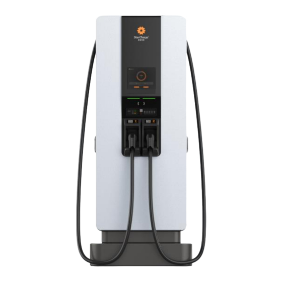
- Page 1 180kW Super Plus DC Charger Instruction Manual Wanbang Charging Equipment Co.,Ltd. The pictures are for reference only...
-
Page 2: Identifying Symbols
Identifying Symbols Identifying Symbols Symbols Meaning “Warning”, which indicates a hazard Pay attention to personal injuries or death caused by operation steps, practice or incorrect implementation. The operation after the "warning" sign can only be performed when the conditions are fully understood and satisfied. “Caution”, which indicates a hazard. -
Page 3: Table Of Contents
Content Content Identifying Symbols ........................... 1 Key information ............................3 1.1 Safety Instruction ..........................3 1.2 Intended use ............................4 1.3 About this Manual ..........................4 Product Overview ............................5 2.1 Product Structure ..........................5 2.2 Product Features ..........................6 2.3 Product Functions .......................... -
Page 4: Key Information
Key information 1. Key information Safety Instruction Symbol Content Failure to follow safety instructions can result in death, injuries and equipment damage. Refuse to bear any claims arising from this. Electrical hazard Only trained, qualified and authorized electrical professionals are responsible for installation. -
Page 5: Intended Use
Key information Be careful Damage hazard. Never use spray water to clean the charging point (hose for garden watering, high-pressure cleaners, or others). 1.2 Intended use This product is an integrated charger that can charge electric powered vehicles (for example, an electric car) in indoor and outdoor areas. -
Page 6: Product Overview
Product Overview 2. Product Overview The integrated charger is a lithium-ion battery charger product designed and manufactured according to the charging requirements of electric vehicle equipment. The product adopts international advanced soft switching technology, featuring high conversion efficiency, stable output current, and high reliability. -
Page 7: Product Features
The pictures are for reference only. When charging is completed, insert the connector into slot [D] for safe storage. 2.2 Product Features Detailed description of product performance DH-DC1800SG40-B Model 800 mm *726.5 mm *1990 mm Dimension 305kg ( Without modules) -
Page 8: Technical Characteristics
Product Overview 3)Support two charging methods: BMS charging mode and manual charging mode. The BMS charging method supports "GB / T 27930-2015 Communication protocol between non-vehicle conductive chargers and battery management systems for electric vehicles" or user-defined protocols. The manual charging method can set the output voltage and current via touch screen, which is suitable for no CAN communication scene. - Page 9 Product Overview to set voltage, current, and charging time, which is suitable for applications without CAN communication. 8)CAN bus is used to realize real-time data exchange with the vehicle to achieve the purpose of smart charging. 9)Power module features: Adopt advanced phase shift resonant high frequency soft switch, active PFC technology, which has high power density, power factor efficiency and low harmonic distortion features.
- Page 10 Product Overview Ambient temp. (℃) Ambient temp. & power curve Figure 2-3: 750V&30kW Power temperature curve Parameter Value Remark Output voltage 200~750V Max. output power of module is 30 kW Max. output power 30kW under normal condition. Max. output current Rated current Rated voltage is 750V Instruction Manual...
-
Page 11: Operation Instruction
Operation Instruction 3. Operation Instruction The charger operation has two parts, the charging connection operation and the equipment operation. To use the product, the user must connect the charger to the vehicle firstly, and then carry out relevant charging operations through the HMI. 3.1 Charging Connection Operation The pictures are for reference only Step 1. - Page 12 Operation Instruction Figure 3-1 Main Interface of Charging (The pictures are for reference only) Step 2 Enter the model setting interface, and select EV models of charging port. Figure 3-2 Model settings (The pictures are for reference only) Step 3 After the setting is completed, click "Confirm" to return to the main interface, click "Charge" and then select "Scan code".
- Page 13 Operation Instruction Figure 3-3 Select charging mode (The pictures are for reference only) Step 4 Click "scan code" to enter QR code interface. Figure 3-4 Scan interface (The pictures are for reference only) Step 5 Open App and click the red button to scan the QR Code on charger’s screen. Instruction Manual Wanbang Charging Equipment Co.,Ltd...
-
Page 14: Swipe The Rfid Card To Charge
Operation Instruction The pictures are for reference only Figure 3-5 APP interface (Take the star charging app as an example) Step 6 During the charging process, the charger’s screen displays the interface as shown in Figure 3-6. The charging state picture here is an example of charging with two connectors at the same time. - Page 15 Operation Instruction Figure 3-7 Main Interface of Charging (The pictures are for reference only) Step 2 Enter the model setting interface, and select EV models of charging port. Figure 3-8 Model settings (The pictures are for reference only) Step 3 After the setting is completed, click "Confirm" to return to the main interface, click "Charge" and select "Swipe card".
- Page 16 Operation Instruction Figure 3-9 Select charging mode (The pictures are for reference only) Step 4 Click" Swipe card " to enter the card swipe interface. Figure 3-9 Swipe Card Charging (The pictures are for reference only) Step 5 Place the RFID card on the swiping area to start charging. Step 6 During the charging process, the charger’s screen displays the interface as shown in Figure 3-10The charging state picture here is an example of charging with two connectors at the same time.
- Page 17 Operation Instruction Figure 3-10 Charging status (The pictures are for reference only) Step 7 After fully charging, click "Back" to return to the main charging interface. You can also stop charging by clicking the stop button on Star Charge APP or the "Stop Charging" button on the charger interface.
-
Page 18: Troubleshooting
Troubleshooting 4. Troubleshooting Fault Possible causes and Solutions No power supply. Check the protection switch od circuit, restart if necessary Damaged, please contact your service partners. Power LED is off Input power is normal. Check the phase sequence to confirm the correct phase sequence of the inlet cable of the charger. - Page 19 Troubleshooting Abnormal communication of power module stops during Check front - end relay for suction. charging Instruction Manual Wanbang Charging Equipment Co.,Ltd...
-
Page 20: Routine Maintenance
Routine Maintenance 5. Routine Maintenance 5.1 Power distribution system Power on and off steps of the distribution box. Check if the supply voltage is normal. Power on: first turn on the main switch of the distribution box and then the branch circuit switch. Power off: first turn off the branch circuit switch, and then turn off the main switch of the distribution box. -
Page 21: Auxiliary System
Routine Maintenance Quarterly routine inspection: check whether the circuit components are fixed firmly and if there is a phenomenon of fire burning at the connection of the components. If any abnormality is found, please replace the components as fast as possible. ... -
Page 22: Electrical Ground System
Routine Maintenance Figure 5-1 Left fan mounting plate Figure 5-2 replace the filter assembly 2. Open the right door and unscrew the three butterfly nuts on the right door fan mounting plate, Remove the filter platen and replace the filter assembly. Figure 5-3 Right fan mounting plate ... -
Page 23: Appearance
Routine Maintenance If the grounding equipment is not solid, reliable and does not conform to the standard requirements, it will inevitably lead to security risks, and there is always the possibility of personal and equipment safety crisis. Therefore, careful inspection and timely maintenance must be carried out to make the ground system always operate in a safe state. -
Page 24: Emergency Treatment
Routine Maintenance Maintenance Dust inspection of √ √ √ √ control board Clean 5.8 Emergency Treatment In order to maintain the DC power supply of the integrated charger without interruption, it is necessary to take several emergency measures for the DC supply failures. The faults that may occur in the power system that cause the DC output to be interrupted include: irreversible damage of the AC power distribution circuit, DC load short circuit or DC power distribution shutdown because of the monitoring module damage and the blockage of the module caused by DC... -
Page 25: Customer Service
Record the model and serial number of the device (the nameplate of the device). 6.2 Contact Information Company address: No.39, Longhui Road, Wujin High-tech zone, Changzhou, Jiangsu, China. Website: www.starcharge.com Company E-mail: wanbang@wanbangauto.com Hotline in China: 400-828-0768 Instruction Manual... -
Page 26: Appendix
Appendix Appendix The following documents are this product’s standards design. GB / T 18487.1-2015 General requirements for charging systems GB / T 18487.2-2017 Conductive charging system for electric vehicles Part 2: Requirements for electromagnetic compatibility of non-vehicle conductive power supply equipment ... - Page 27 Appendix GBT 20234.3-2015 Connecting device for conductive charging of electric vehicles Part 3: DC charging interface GBT 27930-2015 Communication protocol between electric vehicle non-vehicle conductive charger and battery management system NB / T 33001-2018 Technical Conditions for Non-vehicle Conductive Charger for Electric Vehicles ...
-
Page 28: Warranty Card
Warranty Card B. Warranty Card C.1 Warranty Terms and Conditions Basic information Welcome to buy products for Jiangsu Wanbang Dehe New Energy Technology Co., LTD. 2、 If there are any requirements for the products purchased or used that exceed the standard warranty, please call 400-828-0768 to learn about various warranty upgrades and extended warranty services. - Page 29 Warranty Card Warranty period User name Contact Phone number Contact address Dealer stamp Instruction Manual Wanbang Charging Equipment Co.,Ltd...
Need help?
Do you have a question about the DH-DC1800SG40-B and is the answer not in the manual?
Questions and answers