Table of Contents
Advertisement
Quick Links
Advertisement
Table of Contents

Subscribe to Our Youtube Channel
Related Manuals for St. Jude Medical CardioMEMS CM3000


Summary of Contents for St. Jude Medical CardioMEMS CM3000
- Page 1 CardioMEMS™ HF System Model CM3000 System Guide...
- Page 2 Unless otherwise noted, ™ indicates that the name is a trademark of, or licensed to, St. Jude Medical or one of its subsidiaries. ST. JUDE MEDICAL and the nine-squares symbol are trademarks and service marks of St. Jude Medical, Inc. and its related...
-
Page 3: Table Of Contents
Contents Description ................................1 Indications ................................1 Contraindications ..............................1 Warnings ................................. 1 Precautions ................................2 Package Contents ..............................2 Sterilization ................................2 The Patient and Hospital Electronics Systems ......................3 The Antenna ..................................3 Components and Setup ............................3 Connect the System Cables .............................. - Page 4 Guidelines for the Management of Hemodynamic Parameters ................21 Elevated PA Pressures (Hyper-volemic) ........................21 Low PA Pressures (Hypo-volemic) .......................... 22 Recommended Frequency of CardioMEMS HF System Review ................22 Cleaning ................................22 Storage .................................. 22 User/Owner Responsibility ............................. 22 Electromagnetic Interference and Electromagnetic Compatibility ................
-
Page 5: Description
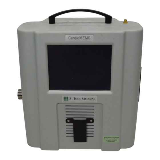
Description The CardioMEMS™ HF System provides pulmonary artery (PA) hemodynamic data used for monitoring in the management of heart failure (HF). The system measures PA pressure, and the data is used by the physician to initiate or modify heart failure treatment and manage heart failure. -
Page 6: Precautions
Ingestion of any part of the system may cause injury. Care should be taken to keep all cables away from the neck and face to prevent airway blockage. If the patient develops redness of the skin or a change in skin sensitivity occurs, they should discontinue use of this product ... -
Page 7: The Patient And Hospital Electronics Systems
The Patient and Hospital Electronics Systems The Patient and Hospital Electronics Systems are designed to obtain information from the sensor. The functional components of the hardware include an electronics unit and an antenna. The antenna simultaneously sends a Radio Frequency (RF) signal to energize the sensor and measures the RF signal returned by the sensor. -
Page 8: The Printer
Figure 3. Connect the antenna Attach the connectors as shown in the figure below. You can connect an optional VGA cable to the auxiliary VGA connector. Figure 4. The connectors Power switch Power cable (5 pin DIN) Printer serial cable (9 pin D-SUB) VGA connection Printer power cable Plug the power cord into the power supply and plug the power cord into the wall. -
Page 9: The Pole Attachment
The Pole Attachment To mount the electronics unit to a pole, use the pole clamp. Follow these guidelines: Use a pole that is sturdy, has locking wheels, and can remain stable at an incline of 10 degrees. If the pole is on an incline, it may experience an initial settling movement before it stabilizes. Maintain control of the pole until it ... - Page 10 Figure 7. The New Implant button Select the New Implant button. The list of patients you entered on the website appears on the screen. Select a patient from the list and then select the OK button. After the sensor information loads, it appears on the screen along with the patient information. Verify that the patient information is correct.
-
Page 11: Acquire The Sensor Signal
Figure 9. The Demographics screen Enter the patient information using the touchscreen keyboard. To modify a field, touch the desired field. Make sure you fill out the first and last name fields and the birthdate field. The phone number field is optional. All of this information appears on the website once the implant is complete. Select the OK button. -
Page 12: Take A Reading
Figure 11. The Pressure Baseline screen Wait for the screen to refill with a stable pressure waveform and then confirm that the sensor mean pressure matches the catheter PA mean pressure within +/- 1 mmHg. Repeat this step as necessary to achieve a good match between the measurements. Confirm that the height of the sensor signal pressure (systolic - diastolic) is within +/- 25% of the height of the catheter pressure. -
Page 13: Transfer The Data
Figure 13. The PA catheter pressure reading If the reading is acceptable, select the Yes button. If not, select the No button and repeat the reading. Reconfirm that the sensor mean pressure matches the catheter PA mean pressure within +/- 1mmHg. Check the setup and if necessary, set the PA pressure baseline again to achieve a good match between the measurements. -
Page 14: Setup With A Wireless Connection
The two options for the setup are: From the website using wireless connectivity From the electronics unit using a USB flash drive A manual option is available as a backup method. Refer to the Manual Setup Instructions section for instructions. Figure 14. -
Page 15: Setup Without A Wireless Connection
Figure 17. The Serial Number screen To enter the the 6 digit serial number located on the patient's identification card, select the Enter button and then type in the serial number using the touchscreen keyboard. Figure 18. The Verification screen Verify that the patient information and the sensor information is correct. -
Page 16: Patient Training
Figure 20. The USB screen Select the OK button on the Insert Website USB screen to load the data from the website. If there are multiple patients found on the USB flash drive, screens for each patient on the USB flash drive appear. Figure 21. -
Page 17: Pulmonary Artery Catheter Setup
If the Shift Position screen appears, have the patient move positions to find the best position. Once a good signal is available, the system says "Good Position on Pillow, Stay Still", and then begins to play music. WARNING Avoid placing the handheld unit directly on the pillow during a reading. A reading takes approximately 18 seconds to complete. -
Page 18: Acquire The Sensor Signal
You can search the list by entering information into the search box at the top of the screen. Select the desired patient from the list. Select the OK button. Without a Wireless Connection To retrieve the patient information: Insert a USB flash drive into the USB port of the computer. On the Merlin.net™... -
Page 19: Optimize The Signal Strength
Optimize the Signal Strength Use fluoroscopy to improve the position of the antenna relative to the implanted sensor. If the signal strength is not optimal (<70% or not green), follow the steps below. Align the center of the antenna with the sensor and adjust the antenna to maximize the signal strength. If the signal strength is optimal (>70%), return to the Acquire the Sensor Signal section and resume where you left off. -
Page 20: Patient Position
Figure 25. Technically suspect readings with low signal strength The waveform in the figure above is pulsatile with a heartbeat but at a high pressure that does not make sense for the patient. For all technically suspect readings, if the reported mean pressure reads above or below the value from the pulmonary artery catheter: ... -
Page 21: Manual Setup Instructions
Table 1. Troubleshooting Problem Symptom Solution Touchscreen does Buttons are not activated by repeated Turn off the system by holding in the power button on the back of not respond presses the electronics unit for greater than 5 seconds. Turn on the system and retry to use the touchscreen. -
Page 22: Patient Electronics System
Verify that the information is correct. Patient Electronics System To set up the Patient Electronics System without using a USB flash drive, you need the following: Patient information Sensor information Baseline information Four digit activation code This information is available on the implant report from the website. -
Page 23: The Settings Screen
The Settings Screen Figure 26. The Settings screen From the Settings screen, you can access additional system functions. These include: Patient Options: Use the Patient Options button to do the following: Print any previously captured images Export information from the USB flash drive for upload into the website Display the baseline information for manual input into the website Password. -
Page 24: Software Update
Update button. If your Hospital Electronics System does not have a network connection, software updates are installed with a USB flash drive by St. Jude Medical™. Additional Patient Electronics System Functions This section explains additional functions of the Patient Electronics System. -
Page 25: Guidelines For The Management Of Hemodynamic Parameters
Figure 28. The pressure values Guidelines for the Management of Hemodynamic Parameters The CardioMEMS HF System allows intermittent assessment of pulmonary artery systolic, diastolic and mean pulmonary artery pressures. Hemodynamic information obtained by the system should be used for clinical decision making in addition to symptoms, weights or physical examination (traditional markers of volume). -
Page 26: Low Pa Pressures (Hypo-Volemic)
Low PA Pressures (Hypo-volemic) Hypo-volemic Definitions Subject symptoms: poor perfusion in absence of signs and symptoms of congestion CardioMEMS HF System Parameters: below the acceptable range Daily trends: decrease in trend data outside the acceptable range Weekly trends: decrease in trend data ... -
Page 27: Electromagnetic Interference And Electromagnetic Compatibility
Electromagnetic Interference and Electromagnetic Compatibility This section provides a brief overview of Electromagnetic Interference and Electromagnetic Compatibility guidance associated with the use of the CM3000. Table 2. Electromagnetic Emissions Guidance and manufacturer’s declaration – electromagnetic emissions The electronics unit is intended for use in the electromagnetic environment specified below. The customer or the user of the electronics unit should assure that it is used in such an environment. - Page 28 Table 3. Electromagnetic Immunity Guidance and manufacturer’s declaration – electromagnetic immunity The electronics unit is intended for use in the electromagnetic environment specified below. The customer or the user of the electronics unit should assure that it is used in such an environment. Immunity Test IEC 60601 Compliance level...
-
Page 29: Fcc And Industry Canada Statement
Table 4. Recommended separation distances between portable and mobile RF communications equipment and the electronics unit The electronics unit is intended for use in an electromagnetic environment in which radiated RF disturbances are controlled. The customer or the user of the electronics unit can help prevent electromagnetic interference by maintaining a minimum distance between portable and mobile RF communications equipment (transmitters) and the electronics unit as recommended below, according to the maximum output power of the communications equipment. -
Page 30: System Specifications
DEHP is found in the following component(s): Table 5. Component Component Part Amount Present Rigid Antenna CS-000132 Less than 0.8% w/w (weight of substance/weight of product) As a result, there are no restrictions for the user of the rigid antenna in this application. System Specifications Electrical Characteristics Power... -
Page 31: Emi/Emc Testing
Keep dry Affixed in accordance with European Council Directive 90/385/EEC ("0086") and 1999/5/EC ("0982"). Hereby, St. Jude Medical declares that this device is in compliance with the essential requirements and other relevant provisions of these Directives. Authorized EC Representative in the European Community... - Page 32 Sorting such waste and removing it from other forms of waste lessens the contribution of potentially toxic substances into municipal disposal systems and into the larger ecosystem. Return the device to St. Jude Medical at the end of its operating life. Part number Alternating current...
- Page 36 Manufacturer: European Authorized Australian Sponsor: St. Jude Medical Representative: St. Jude Medical Australia Pty. Limited 387 Technology Circle NW St. Jude Medical 17 Orion Road Atlanta, GA 30313 USA Coordination Center BVBA Lane Cove NSW 2066 +1 866 240 3335...
Need help?
Do you have a question about the CardioMEMS CM3000 and is the answer not in the manual?
Questions and answers