Table of Contents
Advertisement
Advertisement
Table of Contents

Related Manuals for St. Jude Medical CardioMEMS CM3000


Summary of Contents for St. Jude Medical CardioMEMS CM3000
- Page 1 CardioMEMS™ HF System Model CM3000 System Guide...
- Page 2 Do not attempt to use the device before reading and fully understanding the User’s Manual and the System Guide. Carefully inspect all product packaging for damage or defects prior to use. CAUTION: Federal (USA) law restricts this device to sale by or on the order of a physician. Unless otherwise noted, ™...
-
Page 3: Table Of Contents
Contents Description ................................1 Indications ................................1 Contraindications ..............................1 Warnings ................................. 1 Precautions ................................2 Package Contents ..............................2 Sterilization ................................3 Components and Setup ............................3 Connect the System Cables ..............................3 Printer ....................................3 The Pole Attachment ................................4 Hospital Electronics System Password Access ........................ - Page 4 Additional Hospital Electronics System Functions ....................38 A. Wireless Connectivity Setup ............................. 38 B. Setting Baseline in Follow-Up Reading ..........................38 C. Settings Screen................................39 D. The Admin Screen ................................39 Software Update ................................. 40 Additional Patient Electronics System Functions ..................... 40 Patient Electronics System - Viewing Pressure Values During the Reading ................
-
Page 5: Description
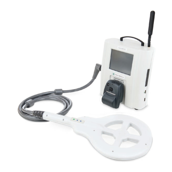
Description The CardioMEMS HF System provides pulmonary artery (PA) hemodynamic data used for the monitoring and management of heart failure (HF) patients. The system measures changes in PA pressure which physicians use to initiate or modify heart failure treatment. The system includes the following components: Implantable wireless sensor with delivery catheter ... -
Page 6: Precautions
All sensors have a unique calibration. Ensure readings are only taken using the correct calibration information from the sensor. Use of the incorrect calibration information may result in an inaccurate reading. All right heart catheterizations must be performed under fluoroscopic guidance to prevent sensor dislodgement. ... -
Page 7: Sterilization
Sterilization The Hospital Electronics System is provided non-sterile. Components and Setup Connect the System Cables Align the keyed antenna at an approximately 30 degree angle and twist on the locking connector. Figure 1. Connecting the antenna Attach the connectors as shown in the figure below. Connectors: Power supply connector (5 pin DIN) Printer serial communication cable (9 pin D-SUB ) -
Page 8: The Pole Attachment
Figure 3. The printer mount The Pole Attachment To mount the electronics unit to a pole, use the pole clamp. Ensure that the pole is sturdy and can remain stable when at an incline of 10 degrees. Recommended pole: Pryor Products, Inc. -
Page 9: Patient And Hospital Electronics Systems
Patient and Hospital Electronics Systems The CardioMEMS PA Sensor is implanted into a distal branch of the descending PA. Following implantation, patients are instructed to take pressure readings from home as directed by their physician. The information transmitted to the database is immediately available to clinicians for review. -
Page 10: Overview
Overview Implant Procedure Overview For detailed instructions, refer to the following sections: New Sensor Implant - Wireless Connection Available New Sensor Implant - No Wireless Connection Available New Sensor Implant - Wireless Connection Available This section presents using the Hospital Electronics System to perform a sensor implant when a wireless connection is available for communication with the Merlin.net Patient Care Network Heart Failure Management Application. - Page 11 Figure 7. Main screen, select New Implant. Figure 8. Select patient from list downloaded from Merlin.net Patient Care Network Heart Failure Management Application. NOTE: All screenshots are simulations and do not represent actual patients or actual patient data. Figure 9. Insert USB drive if prompted. This screen will not appear if USB drive was already inserted.
-
Page 12: Step 2: Acquire Signal
Figure 10. Verify patient and sensor information. Step 2: Acquire Signal Once you have loaded the patient and sensor information into the Hospital Electronics System and then implanted the sensor, the steps below describe how to set the pulmonary artery (PA) pressure baseline. Place the antenna under the patient’s back, approaching from the side where the sensor was placed. - Page 13 Figure 12. Setting PA Pressure Baseline. Wait for the screen to re-fill with a stable pressure waveform and then confirm that the sensor mean pressure matches the catheter PA mean pressure within +/- 1mm Hg. Repeat the PA Baseline step as necessary to achieve a good match between measurements.
-
Page 14: Step 4: Take Reading
Figure 14. Enter Reference Cardiac Output to Set Baseline. Enter the reference cardiac output value and select OK. Step 4: Take Reading Once you are satisfied with the PA pressure baseline, take as many pressure readings as desired. Establishing accurate baseline PA pressure at the time of implant is important to ensure accurate PA pressure readings from home. -
Page 15: Step 5: Transfer Data
Figure 16. Pulmonary Artery Catheter Pressure Reading If the reading is acceptable, select the Yes button to save the reading. If the reading is unacceptable, select the No button and repeat the reading. Re-confirm that the sensor mean pressure matches the catheter PA mean pressure within +/- 1mm Hg. Check the setup and if necessary, set the PA Pressure Baseline again to achieve a good match between measurements. -
Page 16: New Sensor Implant - No Wireless Connection Available
New Sensor Implant – No Wireless Connection Available This section presents the use of the Hospital Electronics System to perform a sensor implant when a wireless connection is not available for communication with the Merlin.net Patient Care Network Heart Failure Management Application. The patient information is entered manually on the Hospital Electronics System. - Page 17 Figure 19. Enter patient demographic information. Figure 20. Enter patient information using touch keyboard. Figure 21. Insert USB drive if prompted. This screen will not be shown if the USB drive was already inserted.
-
Page 18: Step 2: Acquire Signal
Figure 22. Verify patient and sensor information. Step 2: Acquire Signal Once you have loaded the patient and sensor information into the Hospital Electronics System and then implanted the sensor, the steps below describe how to set the pulmonary artery (PA) pressure baseline. Place the antenna under the patient’s back, approaching from the side where the sensor was placed. - Page 19 Figure 24. Setting PA Pressure Baseline. Wait for the screen to re-fill with a stable pressure waveform and then confirm that the sensor mean pressure matches the catheter PA mean pressure within +/- 1mm Hg. Set the PA Pressure Baseline step again as necessary to achieve a good match between measurements.
-
Page 20: Step 4: Take Reading
Figure 26. Enter Reference Cardiac Output to Set Baseline. Enter the reference cardiac output value and select OK. Step 4: Take Reading Once you are satisfied with the PA pressure baseline, take as many pressure measurements as desired. Establishing accurate baseline PA pressure at the time of implant is important to ensure accurate PA pressure readings from home Select the Take Reading button to capture pressure measurements. -
Page 21: Step 5: Transfer Data
Figure 28. Pulmonary Artery Catheter Pressure Reading. If the reading is acceptable, select the Yes button to save the reading. If the reading is unacceptable, select the No button and repeat the reading. As was discussed in the Step 2: Acquire Signal section above, re-confirm that the sensor mean pressure matches the catheter PA mean pressure within +/- 1mm Hg. -
Page 22: Merlin.net Patient Care Network Heart Failure Management Application Setup
Figure 30. Main screen, Select Shut Down Allow the system to complete the shut-down sequence prior to disconnecting power from the system. CAUTION: Disconnecting power before the shut-down sequence is completed may cause file corruption. Merlin.net Patient Care Network Heart Failure Management Application Setup The Merlin.net Patient Care Network Heart Failure Management Application is the central window from which to view the status of your patient. -
Page 23: Setup - Wireless Connection Available
Locally on the electronics using the USB flash drive A third option is available as a backup method in case the primary methods are unavailable See Manual Setup Instructions section. In this option, no USB flash drive is used and all of the information is entered via the touch screen. Setup –... -
Page 24: Setup - No Wireless Connection Available
Figure 35. Confirm patient and sensor information Figure 36. Patient name will be displayed on starting screen Setup - No Wireless Connection Available When the system starts, wireless connectivity may be unavailable for the following reasons. The system has a dial up telephone modem. ... - Page 25 Figure 37. Select the Other button Figure 38. USB screen Figure 39. Confirm patient and sensor information. Figure 40. Patient name will be displayed on start screen...
-
Page 26: Patient Training
Patient Training Discuss the information in the Patient Instructions and Patient System Guide with your patient before and after sensor implantation. For additional copies of the patient’s guide, contact Technical Support. You should also explain the established benefits and risks of the CardioMEMS HF System with the patient. -
Page 27: Overview
Figure 43. Connection in Progress. If cellular coverage is available, the system will send the data and shut down following transmission. If wireless coverage is not available or if the system uses a dial-up connection, select Cancel to stop the system from continuing to attempt the connection. -
Page 28: Step 2: Acquire Signal
Figure 44. Select Follow-Up. Figure 45. Select desired patient from the list. Step 2: Acquire Signal Place the antenna under the patient’s back, approaching from the side where the sensor was placed. Position the center of the antenna under the tip of the patient’s shoulder blade on the side of the torso where the sensor is located. The preferred location for sensor placement is on the left side. -
Page 29: Step 4: Transfer Data
Figure 46. Follow-up Pressure Reading. The captured reading is displayed for confirmation. The colored horizontal lines indicate the catheter pressure values entered as reference (if available). The green line indicates systolic pressure, blue indicates mean pressure, and red indicates diastolic pressure. -
Page 30: Step 1: Retrieve Patient Information [Follow Up No Wireless]
Step 1: Retrieve Patient Information [follow up no wireless] Insert a USB flash drive into the USB port of the computer. On the Merlin.net Patient Care Network Heart Failure Management Application, use the Export feature beneath the More Actions link on the Patient Profile tab for your patient. For more information consult the Merlin.net Patient Care Network Heart Failure Management Application Help Manual. -
Page 31: Step 2: Acquire Signal
Figure 50. Insert USB Drive when prompted. Figure 51. Confirm patient and sensor information. Step 2: Acquire Signal Insert the antenna under the patient’s back, approaching from the side where the sensor was placed. Position the center of the antenna under the tip of the patient’s shoulder blade on the side of the torso where the sensor is located. The preferred location for sensor placement is on the left side. -
Page 32: Step 4: Transfer Data
Figure 52. Follow-up Pressure Reading. The captured reading is displayed for confirmation. The colored horizontal lines indicate the catheter pressure values entered as reference (if available). The green line indicates systolic pressure, blue indicates mean pressure, and red indicates diastolic pressure. -
Page 33: Locating Sensor Signal
Locating Sensor Signal This section outlines procedures to help locate the sensor signal. A. Optimize Signal Strength Follow this procedure if the signal strength is not optimal (<70% or not green). Use fluoroscopy to improve the position of the antenna relative to the implanted sensor. Align the center of the antenna with the sensor and adjust the antenna to maximize the signal strength. -
Page 34: Technically Suspect Readings
B. Technically Suspect Readings Technically suspect readings are readings which result from a signal other than the sensor. If you receive technically suspect readings that have a high signal strength (> 70% ) within the search range of the sensor: Be aware of the angulation of the sensor relative to the antenna and have the patient shift positions until the suspect reading ... -
Page 35: Angulation
Ask the patient to press the antenna firmly into their back as much as is still comfortable. Ask the patient to remove all metallic objects. Have the patient shift into different positions. D. Angulation The signal strength is strongest when the antenna and sensor are parallel. Try these steps to change the angulation: Ask the patient to orient and locate the antenna over the position of the sensor. -
Page 36: Pulmonary Artery Catheter Setup
Table 1. Troubleshooting Problem Symptom Solution Error #3 Important data needed to make a measurement was not available. Error #4 The internal settings values needed to make a measurement were missing or damaged. Error #5 The atmospheric pressure sensor indicated an error in recording pressure or temperature. - Page 37 When prompted for the USB flash drive from the sensor package, select ‘Enter Manually’. Use the touch screen to enter the sensor serial number and calibration code using the label on the sensor package. After the sensor information is loaded, it will be displayed along with the patient information. Verify that Sensor Serial displayed matches the Serial Number printed on the sensor box.
-
Page 38: Patient Electronics System Setup
Figure 61. For manual entry of sensor information, touch ‘Enter Manually’. Figure 62. Enter sensor information from sensor package. Figure 63. Verify patient and sensor information. Patient Electronics System Setup This is a backup option if the cellular connection is unavailable and you are unable to use a USB flash drive to retrieve the sensor information from the Merlin.net Patient Care Network Heart Failure Management Application. - Page 39 These steps will require the patient information, the sensor characteristics and the baseline information be available. In addition, a 4 digit code is needed from the website. All of this information is available on the implant report which is printed from the Merlin.net Patient Care Network Heart Failure Management Application.
-
Page 40: Follow-Up
Figure 67. Confirm patient and sensor information. Figure 68. Patient name will be displayed on starting screen every time the system is started. Follow-Up Select Follow-Up. You will be presented with the list of patients that are available on this electronics unit. Select the button ‘Add…’ below the list. Select ‘Enter Manually’. - Page 41 Figure 70. In this case, the patient is not available, select ‘Add…’ from below the list. Figure 71. Select Manual Entry when prompted. Figure 72. Enter the patient and sensor information.
-
Page 42: Additional Hospital Electronics System Functions
Figure 73. Confirm patient and sensor information. Additional Hospital Electronics System Functions A. Wireless Connectivity Setup The Hospital Electronics System can be configured to communicate with the Merlin.net Patient Care Network Heart Failure Management Application using local WiFi or cellular using the built-in GSM antenna. WiFi is not installed by default. -
Page 43: Settings Screen
Figure 75. Setting Baseline in Follow-Up Select Set Pressure Baseline or Set CO Baseline to adjust baselines. Refer to the section Step 3: Set Baseline for instructions on properly setting the baseline. If there is any change to the baseline it is important to transfer the information back to the Merlin.net Patient Care Network Heart Failure Management Application so that the system in your patient’s home uses the updated baseline. -
Page 44: Software Update
Enter the username and password of a Merlin.net PCN administrator on the User Log On screen and then select the OK button. Select the Settings button on the CardioMEMS HF screen. The Settings screen appears. On the Settings screen, select the Service button. On the Service screen, select the Admin button. -
Page 45: Guidelines For The Management Of Hemodynamic Parameters
Figure 77. Enable reading values. Press the round green button below the touchscreen on the handheld unit. Have the patient get in position and then start the reading. During the reading, the screen will show the reading values as below. Figure 78. -
Page 46: Low Pa Pressures (Hypo-Volemic)
Subject symptoms: Congestive symptoms (wet) CardioMEMS HF System Parameters: above the acceptable range Daily trends: elevated trend data outside the acceptable range Weekly trends: elevation in trend data Treatment Recommendations Add or increase diuretic (and appropriate electrolyte replacement) ... -
Page 47: Purpose
PA pressure while the patient is at home allowing them to manage patients proactively with the goal of reducing heart failure hospitalizations. CHAMPION (CardioMEMS HF Sensor Allows Monitoring of Pressures to Improve Outcomes in NYHA Functional Class III Heart Failure Patients) was a prospective, multicenter, single-blind, randomized, clinical trial in 550 patients across 64 centers in the United States. -
Page 48: Primary And Secondary Endpoint Results
Table 2. Patient Demographics Randomized Group Treatment Control Variables (N=270) (N=280) p-value Hypertension 207/270 (76.7%) 220/280 (78.6%) 0.6100 Hyperlipidemia 204/270 (75.6%) 218/280 (77.9%) 0.5458 Coronary Artery Disease 182/270 (67.4%) 202/280 (72.1%) 0.2290 History of MI 134/270 (49.6%) 137/280 (48.9%) 0.9320 Diabetes Mellitus 130/270 (48.1%) 139/280 (49.6%) -
Page 49: Results From The Entire Randomized Access Period
Table 5. Primary Safety Endpoint – Freedom from Pressure Sensor Failures Pressure Sensor Lower 95.2% Confidence Objective Performance Criterion p-value Failures (n=550) Limit (OPC) 0 (0.0%) 550 (100%)1 99.3% p<0.0001 Primary Efficacy Endpoint The primary efficacy endpoint of the CHAMPION trial was the rate of HF hospitalizations during the first 6 months of Randomized Access. - Page 50 effect during the entire Randomized Access period was slightly larger than that seen during the 6-month primary endpoint period (33% vs. 28%), indicating durability of the treatment effect. The number needed to treat (NNT) per year to prevent one HF hospitalization was 4.
- Page 51 to have HF hospitalizations. Figure 79 examines Freedom from HF Hospitalization or Death and indicates a non-significant trend favoring women in the treatment group. Figure 79. Freedom from HF Hospitalization over the Full Randomized Period (Part 1). Figure 80. Freedom from Death over the Full Randomized Period (Part 1). Figure 81.
- Page 52 value of 0.15 is typically used because the analysis is typically not powered appropriately. When considering a p-value of 0.15, there was some evidence of treatment-by-gender interaction in the competing risk analyses under the following models: AG Model with Frailty for Part 1 ...
- Page 53 Table 11. Non-serious Adverse Device Events Over Part 1 and Part 2 Part 1 Part 2 TREATMENT (270) CONTROL (280) ALL PATIENTS (550) Subjects Events Subjects Events Subjects Events Subjects Events General disorders and 1 (0.4%) 1 (16.7%) 4 (1.4%) 6 (54.5%) 5 (0.9%) 7 (41.2%) 0 (0%)
- Page 54 Table 12. Non-Serious Adverse Events not related to the device Over Part 1 and Part 2 Part 1 Part 2 Treatment (270) Control (280) All Patients (550) All Patients (347) Subjects Events Subjects Events Subjects Events Subjects Events Immune system 4 (1.5%) 4 (1.4%) 8 (1.5%)
- Page 55 Table 13. Serious Adverse Events Over Part 1 and Part 2 Part 1 Part 2 Treatment Control All Patients All Patients (270) (280) (550) (347) Subjects Events Subjects Events Subjects Events Subjects Events Coronary artery disease Ventricular arrhythmia Ventricular fibrillation Anginal discomfort Cardiac arrest Ischemic cardiomyopathy...
- Page 56 Table 13. Serious Adverse Events Over Part 1 and Part 2 Part 1 Part 2 Treatment Control All Patients All Patients (270) (280) (550) (347) Subjects Events Subjects Events Subjects Events Subjects Events Ventricular rhythm Wide complex tachycardia Wide complex ventricular tachycardia Asystole Congestive cardiomyopathy End stage heart disease...
- Page 57 Table 13. Serious Adverse Events Over Part 1 and Part 2 Part 1 Part 2 Treatment Control All Patients All Patients (270) (280) (550) (347) Subjects Events Subjects Events Subjects Events Subjects Events Methicillin-resistant staphylococcal aureus sepsis Obstructive pneumonia Otitis media Pneumonia MRSA Prostatitis Escherichia coli Purulent bronchitis...
- Page 58 Table 13. Serious Adverse Events Over Part 1 and Part 2 Part 1 Part 2 Treatment Control All Patients All Patients (270) (280) (550) (347) Subjects Events Subjects Events Subjects Events Subjects Events Bronchitis asthmatic Difficulty breathing Dyspnea exacerbated Exacerbation of asthma Hemoptysis Hypoxia Productive cough...
- Page 59 Table 13. Serious Adverse Events Over Part 1 and Part 2 Part 1 Part 2 Treatment Control All Patients All Patients (270) (280) (550) (347) Subjects Events Subjects Events Subjects Events Subjects Events DVT of legs Aortic stenosis Arterial thrombosis (limbs) Deep vein thrombosis Extremity necrosis Hemorrhage, unspecified...
- Page 60 Table 13. Serious Adverse Events Over Part 1 and Part 2 Part 1 Part 2 Treatment Control All Patients All Patients (270) (280) (550) (347) Subjects Events Subjects Events Subjects Events Subjects Events Unresponsive to stimuli Vasovagal symptoms Weakness left or right side Brain injury Restless leg syndrome Todd's paralysis...
- Page 61 Table 13. Serious Adverse Events Over Part 1 and Part 2 Part 1 Part 2 Treatment Control All Patients All Patients (270) (280) (550) (347) Subjects Events Subjects Events Subjects Events Subjects Events Gastric polyps Gastritis erosive Ileus Incarcerated umbilical hernia Ischemic colitis Melena Odynophagia...
- Page 62 Table 13. Serious Adverse Events Over Part 1 and Part 2 Part 1 Part 2 Treatment Control All Patients All Patients (270) (280) (550) (347) Subjects Events Subjects Events Subjects Events Subjects Events Cardiac resynchronisation therapy Heart transplant Cardiac catheterization Implantable defibrillator replacement Amputation Cardiac ablation...
- Page 63 Table 13. Serious Adverse Events Over Part 1 and Part 2 Part 1 Part 2 Treatment Control All Patients All Patients (270) (280) (550) (347) Subjects Events Subjects Events Subjects Events Subjects Events Femur fracture Fracture rib Fractured hip Fractured nose Fractured pelvis NOS Hematoma traumatic Humerus fracture...
- Page 64 Table 13. Serious Adverse Events Over Part 1 and Part 2 Part 1 Part 2 Treatment Control All Patients All Patients (270) (280) (550) (347) Subjects Events Subjects Events Subjects Events Subjects Events Anemia Thrombocytopenia Anemia microcytic Leukocytosis Neutropenia Anemia aggravated Hemolysis Neutropenic fever Investigations...
-
Page 65: Cleaning
Table 13. Serious Adverse Events Over Part 1 and Part 2 Part 1 Part 2 Treatment Control All Patients All Patients (270) (280) (550) (347) Subjects Events Subjects Events Subjects Events Subjects Events Breast cancer Esophageal cancer Lymphoma Endocrine disorders 2 (0.7%) 1 (0.4%) 3 (0.5%) -
Page 66: Storage
To clean the LCD screen, make sure the electronics unit is in the power off mode. Unplug the monitor from the power source before cleaning. Stand away from the LCD monitor and spray cleaning solution onto a clean lint free cloth. Without applying excessive pressure, clean the screen with a slightly dampened cloth. - Page 67 Table 16. Electromagnetic Immunity Guidance and manufacturer’s declaration – electromagnetic immunity The electronics unit is intended for use in the electromagnetic environment specified below. The customer or the user of the electronics unit should assure that it is used in such an environment. Immunity Test IEC 60601 Compliance level...
-
Page 68: Fcc Statement
Rated Maximum output Separation distance according to frequency of transmitter power of transmitter (W) 150 kHz to 80 MHz 80 MHz to 800 MHz 800 MHz to 2,7 GHz d = 1.2 √P d = 1.2 √P d = 2.3 √P 0.01 0.12 m 0.12 m... -
Page 69: Mechanical Characteristics
Mechanical Characteristics Main Unit Weight: approximately 8 pounds Dimensions: Height:11.5 inches Width: 10.5 inches Length: 5.5 inches Product Life: 5 years I/O: 2 USB, RS-232 Printer: FP-900064 Optional WIFI adapter: CM3040 Display Touchscreen: Resistive ... -
Page 70: Technical Support
Technical Support In North America: For Merlin.net™ PCN patients, telephone Technical Support is available Monday through Friday (8AM to 8PM Eastern Standard Time). For clinicians, telephone Technical Support is available 24-hours a day. For Merlin.net Patient Care Network support: 1 877 696 3754 (1 877 MY MERLIN) (toll-free within North America) In Europe: Telephone Technical Support is available Monday through Friday (8:00 to 17:00 Central European Time). - Page 71 Symbol Description Manufacturing Facility Australian Communications and Media Authority (ACMA) and New Zealand Radio Spectrum Management (RSM) Regulatory Compliance Mark (RCM) For prescription use only Conforms to AAMI Std ES60601-1 IEC Std 60601-1-11 Certified to CAN/CSA std C22.2 No. 60601-1...
- Page 72 St. Jude Medical 387 Technology Circle NW Atlanta, GA 30313 USA +1 866 240 3335 St. Jude Medical St. Jude Medical One St. Jude Medical Drive 387 Technology Circle NW St. Paul, MN 55117-9913 USA Atlanta, GA 30313 USA sjm.com 2017-07 ARTEN600007895 A...
Need help?
Do you have a question about the CardioMEMS CM3000 and is the answer not in the manual?
Questions and answers