
Subscribe to Our Youtube Channel
Related Manuals for EWM forceTig 1002


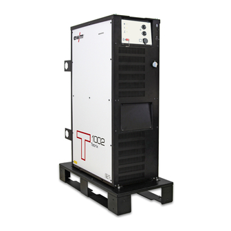
Summary of Contents for EWM forceTig 1002
- Page 1 Operating instructions Power source forceTig 1002 099-000161-EW501 Observe additional system documents! 28.03.2024...
- Page 2 +49 2680 181-0. A list of authorised sales partners can be found at www.ewm -group.com/en/specialist-dealers. Liability relating to the operation of this equipment is restricted solely to the function of the equipment. No other f orm of liability, regardless of type, shall be accepted.
-
Page 3: Table Of Contents
Contents Notes on using these operating instructions Contents 1 Contents........................3 2 For your safety......................6 Notes on using these operating instructions ............... 6 Explanation of icons ....................7 Saf ety instructions ....................8 Transport and installation ..................11 3 Intended use ........................13 Applications......................13 Use and operation solely with the following machines ..........13 Documents which also apply ...................13... - Page 4 Disposing of equipment..................50 7 Rectifying faults ......................51 Checklist for rectifying faults ...................51 Warnings ......................53 Machine faults (error messages)................54 8 Technical data ......................56 forceTig 1002 .......................56 9 Accessories.........................57 System components ....................57 9.1.1 Wire f eed unit..................57 9.1.2 Media separation box ................57 9.1.3...
- Page 5 Contents Notes on using these operating instructions 099-000161-EW501 28.03.2024...
-
Page 6: For Your Safety
For your safety Notes on using these operating instructions For your safety Notes on using these operating instructions DANGER Working or operating procedures which must be closely observed to prevent imminent serious and even fatal injuries. • Saf ety notes include the "DANGER" keyword in the heading with a general warning symbol. •... -
Page 7: Explanation Of Icons
For your safety Explanation of icons Explanation of icons Symbol Description Symbol Description Indicates technical aspects which the Activate and release / Tap / Tip user must observe. Switch of f machine Release Switch on machine Press and hold Incorrect / Invalid Switch Correct / Valid Turn... -
Page 8: Safety Instructions
For your safety Saf ety instructions Safety instructions WARNING Risk of accidents due to non-compliance with the safety instructions! Non-compliance with the safety instructions can be fatal! • Caref ully read the saf ety instructions in this manual! • Observe the accident prevention regulations and any regional regulations! •... - Page 9 For your safety Saf ety instructions WARNING Risk of injury due to improper clothing! During arc welding, radiation, heat and voltage are sources of risk that cannot be avoided. The user has to be equipped with the complete personal protective equipment at all times.
- Page 10 For your safety Saf ety instructions CAUTION Smoke and gases! Smoke and gases may lead to shortness of breath and poisoning! The ultraviolet radia- tion of the arc may also convert solvent vapours (chlorinated hydrocarbon) into poiso- nous phosgene. • Ensure suf f icient f resh air! •...
-
Page 11: Transport And Installation
For your safety Transport and installation CAUTION Obligations of the operator! The respective national directives and laws must be complied with when operating the machine! • Implementation of national legislation relating to framework directive 89/391/EEC on the in- troduction of measures to encourage improvements in the safety and health of workers at work and associated individual guidelines. - Page 12 For your safety Transport and installation CAUTION Risk of accidents due to supply lines! During transport, attached supply lines (mains leads, control cables, etc.) can cause risks, e.g. by causing connected machines to tip over and injure persons! • Disconnect all supply lines bef ore transport! Risk of tipping! There is a risk of the machine tipping over and injuring persons or being damaged itself during movement and set up.
-
Page 13: Intended Use
3.3.1 Warranty For more information refer to the "Warranty registration" brochure supplied and our information regarding warranty, maintenance and testing at www.ewm-group.com! 3.3.2 Declaration of Conformity This product corresponds in its design and construction to the EU directives listed in the decla- ration. -
Page 14: Calibration/Validation
Intended use Documents which also apply 3.3.5 Calibration/Validation An original certificate is enclosed with the product. The manufacturer recommends calibration / validation at intervals of 12 months (f rom commissioning). 099-000161-EW501 28.03.2024... -
Page 15: Part Of The Complete Documentation
Intended use Documents which also apply 3.3.6 Part of the complete documentation This document is part of the complete documentation and valid only in combination with all other parts of these instructions! Read and observe the operating instructions for all system components, especially the safety instructions! The illustration shows a general example of a welding system. -
Page 16: Machine Description - Quick Overview
Machine description – quick overview Front view Machine description – quick overview Front view Figure 4-1 099-000161-EW501 28.03.2024... - Page 17 Machine description – quick overview Front view Item Symbol Description Carrier plate for system components only hot wire version Machine control > see 4.3 chapter Cooling air inlet Operating state signal lamp Lights up when the machine is ready f or use. Collective interference signal light For error messages, Welding process signal lamp...
-
Page 18: Rear View
Machine description – quick overview Rear view Rear view Figure 4-2 099-000161-EW501 28.03.2024... - Page 19 Machine description – quick overview Rear view Item Symbol Description Interfaces connection socket (15-pole) Key button, automatic cutout Wire f eed motor supply voltage f use press to reset a triggered f use 19-pole mechanised welding interface (analogue) > see 5.2.2 chapter Control lead connection, hot wire power source Connection to TIG power source f or hot wire application 19-pole connection socket (analogue)
-
Page 20: Machine Control
Machine description – quick overview Machine control Item Symbol Description Connection thread - G¼" Shielding gas connection (inlet) Mains connection, hot wire power source Power supply f or hot wire power source Mains connection cable > see 5.1.5 chapter Machine control Figure 4-3 Item Symbol Description... -
Page 21: Function Sequence
Machine description – quick overview Machine control Item Symbol Description Signal light Wirefeeder Lights up when wire f eeder f unction is selected Signal light Hotwire Lights up when hotwire f unction is selected Operating mode --- spotArc (Setting range f or spot time 0.01 s to 20.0 s) ---------- Non-latched --------- Special non-latched Display switching push-button... -
Page 22: Connection Plan
Signal light activArc Connection plan 4.4.1 TIG hot wire welding Tetrix Drive 4 Rob 3 HW RINTX12 BUSINTX11 Fassförderung SPS / CU / ROB Tetrix Drive 4 Rob digital only 12 pol Tetrix Hotwire forceTig 1002 Figure 4-5 099-000161-EW501 28.03.2024... -
Page 23: Legend
Machine description – quick overview Connection plan 4.4.1.1 Legend Welding machine supply voltage Shielding gas inlet Welding current (plus potential, workpiece) Wire feeder control cable (12-pole) Wire feeder control cable (7-pole) (Tetrix Drive 4 Rob only) Tetrix Drive 4 Rob only Wire feeding Hose package (HP = hose package) -
Page 24: Tig Welding (Cold Wire)
Machine description – quick overview Connection plan 4.4.2 TIG welding (cold wire) Tetrix drive 4 Rob 3 HW RINTX12 BUSINTX11 SPS / CU / ROB Tetrix Drive 4 Rob digital only 12 pol forceTig 1002 Figure 4-6 099-000161-EW501 28.03.2024... -
Page 25: Legend
Machine description – quick overview Connection plan 4.4.2.1 Legend Welding machine supply voltage Shielding gas inlet Welding current (plus potential, workpiece) Wire feeder control cable (12-pole) Wire feeder control cable (7-pole) (Tetrix Drive 4 Rob only) Tetrix Drive 4 Rob only Wire feeding Hose package (HP = hose package) -
Page 26: Design And Function
Design and function Transport and installation Design and function WARNING Risk of injury from electrical voltage! Contact with live parts, e.g. power connections, can be fatal! • Observe the saf ety inf ormation on the f irst pages of the operating instructions! •... -
Page 27: Ambient Conditions
Design and function Transport and installation Item Symbol Description Rear holder To f ix, push the holder into the machine f eet and secure with f ixing screws. Fixing screws (x 4) 5.1.2 Ambient conditions The machine must not be operated in the open air and must only be set up and operated on a suitable, stable and level base! •... -
Page 28: Mains Connection
Design and function Transport and installation 5.1.5 Mains connection DANGER Hazards caused by improper mains connection! An improper mains connection can cause injuries or damage property! • The connection (mains plug or cable), the repair or voltage adjustment of the device must be carried out by a qualified electrician in accordance with the respective local laws or na- tional regulations! •... -
Page 29: Permitted Torch Coolant
Design and function Transport and installation 5.1.6.1 Permitted torch coolant Coolant Temperature range blueCool -10 -10 °C to +40 °C (14 °F to +104 °F) KF 23E -10 °C to +40 °C (14 °F to +104 °F) blueCool -30 -30 °C to +40 °C (-22 °F to +104 °F) 5.1.6.2 Functional characteristics The machine is equipped with monitoring of coolant f low and temperature. -
Page 30: Notes On The Installation Of Welding Current Leads
Design and function Transport and installation • Plug the quick connect coupling of the welding torch’s coolant return onto the quick-connect nipple (coolant return of the welding torch) of the power source and engage. • Insert the plug nipple of the cooling unit’s coolant return line into the quick connect coupling of the power source and engage f irmly. - Page 31 Design and function Transport and installation • Use an individual welding lead to the workpiece f or each welding machine! Figure 5-5 • Fully unroll welding current leads, torch hose packages and intermediate hose packages. Avoid loops! • Always keep leads as short as possible! Lay any excess cable lengths in meanders.
-
Page 32: Stray Welding Currents
Design and function Transport and installation 5.1.8 Stray welding currents WARNING Risk of injury due to stray welding currents! Stray welding currents can destroy protective earth conductors, damage machines and electronic devices and cause overheating of components, leading to fire. •... -
Page 33: Current Lead Connection
Design and function Transport and installation 5.1.9 Current lead connection WARNING Electric current! When connecting connection leads and interfaces you may come into contact with fatal electric currents! • Follow the saf ety instructions entitled "For your saf ety" on the opening pages! •... -
Page 34: Connection For Workpiece Lead
Design and function Transport and installation 5.1.10 Connection for workpiece lead Figure 5-9 Item Symbol Description Workpiece Load connection screwable potential “+” Workpiece connection > see 5.1.9 chapter • Screw the connection lead to the screw connection, welding current . 5.1.11 Shielding gas supply (shielding gas cylinder for welding machine) WARNING Risk of injury due to improper handling of shielding gas cyli nders! -
Page 35: Shielding Gas Hose Connection
Design and function Transport and installation • Bef ore connecting the pressure regulator to the gas cylinder, open the cylinder valve brief ly to blow out any dirt. • Tighten the pressure regulator screw connection on the gas bottle valve to be gas -tight. •... -
Page 36: Connection Of Media Separation Box
Design and function Transport and installation 5.1.12 Connection of media separation box Read and observe the documentation to all system and accessory components! Figure 5-12 Item Symbol Description Media separation box Observe additional system documents! Intermediate hose package 19-pole connection socket (analogue) Mechanised welding torch connection >... -
Page 37: Connecting The Wire Feed Unit
Design and function Transport and installation • Insert the end of the hose package through the strain relief of the hose package and lock by turning to the right. • Insert the 19-pole control lead plug into the 19-pole connection socket (analogue) and lock. •... -
Page 38: Intermediate Hose Package Strain Relief
Design and function Transport and installation • Insert cable plug on the control lead into the 7-pole connection socket and secure with crown nut (the plug can only be inserted into the connection socket in one position). • Plug the 12-pole cable socket on the control lead into the 12-pole connector plug and secure using crown nut. -
Page 39: Hot Wire Power Source Connection
Design and function Transport and installation 5.1.15 Hot wire power source connection Figure 5-16 Item Symbol Description Hot wire power source Mains connection, hot wire power source Power supply f or hot wire power source hotWire Connection socket, 4-pole Control cable connection, hot-wire power source Connecting plug, welding current "-"... -
Page 40: Welding Torch Connection
Design and function Transport and installation 5.1.16 Welding torch connection Figure 5-17 Item Symbol Description Wire feeder on the torch (Push/Push drive) Welding torch Welding torch hose package 12-pole connection socket Wire f eeder connection to the torch (Push/Push drive) Y adapter cable 19-pole connection socket (analogue) Mechanised welding torch connection >... -
Page 41: Interfaces For Automation
Design and function Interf aces f or automation Item Symbol Description Quick connect coupling, red Coolant return f rom the welding machine or wire f eed unit • Insert the Y adapter cable socket into the machine connector plug and secure with a crown nut. •... -
Page 42: Connecting The Rint X11 Robot Interface/Busint X11 Industrial Bus Interface
Design and function Interf aces f or automation 5.2.1 Connecting the RINT X11 robot interface/BUSINT X11 industrial bus interface Figure 5-18 Item Symbol Description 7-pole connection socket (digital) For connecting digital accessory components Switching cabinet Robot interface / Industrial bus interface Interface casing 7-pole connection cable Connection between switching cabinet and power source... -
Page 43: Rint X12 Robot Interface
Design and function Interf aces f or automation 5.2.1.1 RINT X12 robot interface The standard digital interf ace f or mechanised applications (optional, retrof itting on the machine or external f itting by the customer) Functions and signals: • Digital inputs: start/stop, operating modes, JOB and program selection, inching, gas test •... -
Page 44: Automation Interface
Design and function Interf aces f or automation 5.2.2 Automation interface WARNING No function of the external interrupt equipment (emergency stop switch)! If the emergency stop circuit has been set up using an external interrupt equipment connected to the interface for automated welding, the machine must be configured for this setup. - Page 45 Design and function Interf aces f or automation 19-pole pin assignment for interface for automated welding (X5): Signal form Signal name circuit Function diagram Output Connection f or cable screen Thermal pulse mode up to max. 50 Hz, f ixed balance of Input Pulses on Input...
-
Page 46: Connection Socket Automation Torch
Design and function Interf aces f or automation 5.2.3 Connection socket automation torch Figure 5-20 Connection socket19-pole Automation torch (X22): Signal Signal name designation shape Output Connection f or cable screen Output BR. KOLL. 1 Emergency shut-down collision protection Input BR. -
Page 47: Pc Interface
Design and function PC interf ace PC interface 5.3.1 Connecting the PC 300.net welding parameterisation software Create all welding parameters quickly on the PC and easily transf er them to one or more welding ma- chines (accessories, set consisting of sof tware, interf ace, connection leads) Equipment damage or faults may occur if the PC is connected incorrectly! Not using the SECINT X10USB interface results in equipment damage or faults in signal trans- mission. -
Page 48: Maintenance, Care And Disposal
Maintenance, care and disposal General Maintenance, care and disposal General DANGER Risk of injury due to electrical voltage after switching off! Working on an open machine can lead to fatal injuries! Capacitors are loaded with electrical voltage during operation. Voltage remains present for up to four minutes after the mains plug is removed. -
Page 49: Maintenance Work, Intervals
For more information refer to the "Warranty registration" brochure supplied and our information regard ing warranty, maintenance and testing at www.ewm-group.com! 099-000161-EW501 28.03.2024... -
Page 50: Disposing Of Equipment
Inf ormation on returning used equipment or collections can be obtained f rom the respective municipal administration of f ice. Devices can also be returned to EWM sales partners across Europe. Further inf ormation on the topic of the disposal of electrical and electronic equipment can be found on our website at: https://www.ewm-group.com/de/nachhaltigkeit.html. -
Page 51: Rectifying Faults
Rectifying faults Checklist f or rectif ying f aults Rectifying faults All products are subject to rigorous production checks and final checks. If , despite this, something f ails to work at any time, please check the product using the following flowchart. If none of the f ault rectif ication procedures described leads to the correct functioning of the product, please inform your authorised dea- ler. - Page 52 Rectifying faults Checklist f or rectif ying f aults Pore formation Inadequate or missing gas shielding Check shielding gas setting and replace shielding gas cylinder if necessary Shield welding site with protective screens (draughts af f ect the welding result) ...
-
Page 53: Warnings
Rectifying faults Warnings Warnings Depending on the display options of the machine display, a warning message is displayed as f ollows: Display type - machine control Display Graphic display two 7-segment displays one 7-segment display The cause of the warning is indicated by a corresponding warning number (see table). The display of possible warning numbers depends on the machine version (interfaces/functions). -
Page 54: Machine Faults (Error Messages)
Rectifying faults Machine f aults (error messages) Machine faults (error messages) A welding machine error is indicated by the collective fault signal lamp (A1) lighting up and an error code (see table) being displayed in the machine control display. In the event of a machine error, the power unit shuts down. - Page 55 Rectifying faults Machine f aults (error messages) Error Possible cause Remedy Ignition error Check the welding process. Arc interruption Inf orm service. Error in the emergency stop circuit Check the external shutdown devices. Check jumper (interf ace f or automated welding) JP 1 on PCB T320/1.
-
Page 56: Technical Data
Technical data f orceTig 1002 Technical data Performance specifications and guarantee only in connection with original spare and replacement parts! forceTig 1002 Welding current (I 10 A to 1000 A Welding voltage according to standard (U 10,4 V to 34,0 V Duty cycle DC at 40°... -
Page 57: Accessories
Accessories System components Accessories Performance-dependent accessories like torches, workpiece leads, electrode holders or intermediate hose packages are available from your authorised dealer. System components 9.1.1 Wire feed unit Type Designation Item no. T drive 4 Rob 2 Wire f eeder f or automated applications 090-000077-00502 Wire f eeder f or automated applications, gas, opens T drive 4 Rob 3 RE... -
Page 58: Connection Cables, Connection Sockets
Sof tware f or control and status signal analysis 090-008778-00000 Set PC300 / ANALYZER Set comprising PC300.Net and Analyzer sof tware 090-008779-00000 Set: QM software, a dongle (contains the installa- ewm Xnet Starter-Set 091-008788-00001 tion f iles and sof tware licence) Interfaces Type Designation Item no. -
Page 59: Appendix
Appendix JOB-List Appendix 10.1 JOB-List Process Material Wire Seam position Reserved CrNi CrNi CrNi CrNi CrNi ... - Page 60 Appendix JOB-List Process Material Wire Seam position Fe/St Fe/St >3.2 Fe/St Fe/St Fe/St Fe/St ...
- Page 61 Appendix JOB-List Process Material Wire Seam position CuZn CuZn CuZn CuZn CuZn CuZn >3.2 CuZn CuZn CuZn ...
- Page 62 Appendix JOB-List Process Material Wire Seam position Special Special Special Special >3.2 Special Special Special Special Special Special >3.2 TIG manual/TIG classic Classic electrode Reserved...
-
Page 63: Parameter Overview - Setting Ranges
Appendix Parameter overview – setting ranges 10.2 Parameter overview – setting ranges Parameter Display Setting range Comment TIG/plasma Gas pre-f low time Start current AMP% % of main current AMP Up-slope time 20,0 Pulse time 0,01 0,00 - 20,0 Time f rom main current AMP to se- Slope time 0,00 0,00 - 20,0... -
Page 64: Average Shielding Gas Usage
Appendix Average shielding gas usage 10.3 Average shielding gas usage Gas nozzle number 12.5 inch 0.26 0.31 0.37 0.43 0.63 l/min gal/min 1.58 2.11 2.64 3.17 3.96 10.4 Average wire electrode usage 5 m/min – 197 ipm inch .040 .045 .060 Steel kg/h... -
Page 65: Searching For A Dealer
Appendix Searching f or a dealer 10.5 Searching for a dealer Sales & service partners www.ewm-group.com/en/specialist-dealers "More than 400 EWM sales partners worldwide" 099-000161-EW501 28.03.2024...
Need help?
Do you have a question about the forceTig 1002 and is the answer not in the manual?
Questions and answers