
Related Manuals for Aerotech PRO190SLE


Summary of Contents for Aerotech PRO190SLE
-
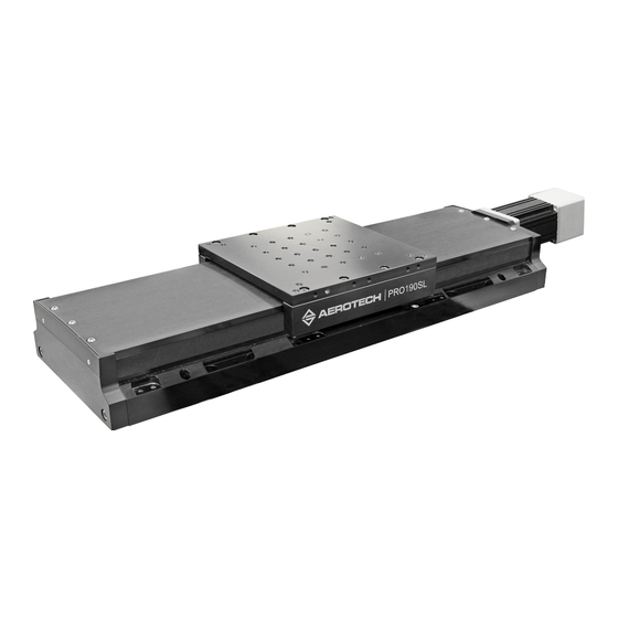
Page 1: Pro190Sl And Sle Mechanical Bearing, Ball-Screw Stage
PRO190SL and SLE Mechanical Bearing, Ball-Screw Stage HARDWARE MANUAL Revision 2.01... - Page 2 Global Technical Support Portal for information and support about your Aerotech, Inc. products. The website supplies software, product manuals, Help files, training schedules, and PC-to-PC remote technical support. If necessary, you can complete Product Return (RMA) forms and get information about repairs and spare or replacement parts.
-
Page 3: Table Of Contents
3.5. Motor and Feedback Phasing Chapter 4: Maintenance 4.1. Service and Inspection Schedule 4.2. Cleaning and Lubrication 4.3. Motor Mounting 4.4. Side Seal Belt Replacement 4.5. Foldback Motor Belt Adjustment 4.6. Troubleshooting Appendix A: Warranty and Field Service Appendix B: Revision History Index www.aerotech.com... -
Page 4: List Of Figures
List of Figures Figure 2-1: PRO190SL Dimensions Figure 2-2: PRO190SL Tabletop Dimensions (-TT2/-TT3 Option) Figure 2-3: PRO190SLE Dimensions Figure 2-4: PRO190SLE Tabletop Dimensions (-TT3) Figure 2-5: Z-Axis Bracket Dimensions Figure 2-6: Stage Orientations Figure 2-7: Cantilevered Load Capability Figure 2-8: Load Torque Equation... -
Page 5: List Of Tables
Table 3-13: Linear Encoder Resolution Specifications Table 3-14: Limit Switch Specifications Table 3-15: Brake Specifications Table 3-16: PRO190SL/SLE Motor Specifications (BMS100) Table 3-17: PRO190SL/SLE Motor Specifications (BM130) Table 4-1: Hardware Requirements Table 4-2: Side Seal Belt Replacement Kit Ordering Guide www.aerotech.com... -
Page 6: Eu Declaration Of Incorporation
PRO190SL/SLE Hardware Manual EU Declaration of Incorporation Manufacturer Aerotech, Inc. 101 Zeta Drive Pittsburgh, PA 15238-2811 herewith declares that the product: PRO190SL/SLE stage is intended to be incorporated into machinery to constitute machinery covered by the Directive 2006/42/EC as amended; and that the following harmonized European standards have been applied:... -
Page 7: Ukca Declaration Of Incorporation
Hardware Manual PRO190SL/SLE UKCA Declaration of Incorporation Manufacturer Aerotech, Inc. 101 Zeta Drive Pittsburgh, PA 15238-2811 herewith declares that the product: PRO190SL/SLE stage To which this declaration relates, meets the essential health and safety requirements and is in conformity with the relevant UK Legislation listed below:... -
Page 8: Safety Procedures And Warnings
To find the newest information about this product, refer to www.aerotech.com. If you do not understand the information in this manual, contact Aerotech Global Technical Support. IMPORTANT: This product has been designed for light industrial manufacturing or laboratory environments. -
Page 9: Installation And Operation
Use care when you move the stage or you could negatively affect the performance of WARNING: Trip Hazard! Route, house, and secure all cables, duct work, air, or water lines. Failure to do so could introduce trip hazards around the system that could result in physical injury or could damage the equipment. www.aerotech.com... -
Page 10: Electrical Warnings
It is the responsibility of the End User/System Integrator to make sure that stages are properly connected and grounded per Engineering Standards and applicable safety requirements. It is the responsibility of the End User/System Integrator to configure the system drive or controller within the Aerotech motor/stage electrical and mechanical specifications. www.aerotech.com... -
Page 11: Motor-Related Warnings
Hardware Manual PRO190SL/SLE Motor-Related Warnings Aerotech motors are capable of producing high forces and velocities. Obey all warnings and all applicable codes and standards when you operate a system that incorporates Aerotech motors. DANGER: Mechanical Hazard! Personnel must be made aware of the mechanical hazards during set up or when you do service to the stage. -
Page 12: Pinch Points
(during normal operation, for example). when the system is moved manually (during the installation process or when you do maintenance, for example). Motors are capable of very high speeds and acceleration rates. Figure 2: Typical Pinch Point Locations www.aerotech.com... -
Page 13: Handling And Storage
Lift this product only by the base. Use lifting hardware if it has been provided (refer to Figure For multi-axis assemblies, always lift the system by the lower axis. Use a cart, dolly, or similar device to move the stage to a new location. www.aerotech.com... - Page 14 Before you operate the stage, let it stabilize at room temperature for at least 12 hours. This will ensure that all of the alignments, preloads, and tolerances are the same as they were when they were tested at Aerotech. Each stage has a label listing the system part number and serial number. These numbers contain information necessary for maintenance or system hardware and software updates.
-
Page 15: Chapter 1: Overview
PRO190SL/SLE Chapter 1: Overview Table 1-1: Model Numbers and Ordering Options PRO190SL and PRO190SLE Series Linear Ball-Screw Stage Direct Linear Feedback (-SLE only) Incremental linear encoder; 1 Vpp Incremental linear encoder; 0.1 µm digital RS422 output Absolute linear encoder; EnDat 2.2 Incremental linear encoder;... - Page 16 PRO190SL/SLE Hardware Manual PRO190SL and PRO190SLE Series Linear Ball-Screw Stage (continued) Foldback (Optional) -FB1 Foldback kit for 1/4" diameter shaft NEMA 23 motor -FB2 Foldback kit with brake for 1/4" diameter shaft NEMA 23 motor -FB3 Foldback kit for 3/8" diameter shaft NEMA 23 motor -FB4 Foldback kit with brake for 3/8"...
-
Page 17: Environmental Specifications
Altitude Operating: 0 m to 2,000 m (0 ft to 6,562 ft) above sea level Contact Aerotech if your specific application involves use above 2,000 m or below sea level. Vibration Use the system in a low vibration environment. Floor or acoustical vibration can affect system performance. -
Page 18: Accuracy And Temperature Effects
Hardware Manual 1.2. Accuracy and Temperature Effects Aerotech products are designed for and built in a 20°C (68°F) environment. Temperature changes could cause a decrease in performance or permanent damage to the stage. At a minimum, the environmental temperature must be controlled to within 0.25ºC per 24 hours to ensure the stage specifications are repeatable over an extended period of time. -
Page 19: Basic Specifications
6. Specifications are for single-axis systems measured 25 mm above the tabletop; performance of multi-axis system depend upon the payload and workpoint. Consult the Aerotech factory for multi-axis or non-standard applications. 7. Specifications listed are non-foldback kit options. Contact the factory for specifications when a foldback kit (-FBx) is used. -
Page 20: Table 1-4: Pro190Sl/Sle Series Specifications (-300 To -800)
6. Specifications are for single-axis systems measured 25 mm above the tabletop; performance of multi-axis system depend upon the payload and workpoint. Consult the Aerotech factory for multi-axis or non-standard applications. 7. Specifications listed are non-foldback kit options. Contact the factory for specifications when a foldback kit (-FBx) is used. -
Page 21: Vacuum Operation
6. To reduce outgassing during the initial pump-down to vacuum pressure, Aerotech recommends that you bake out vacuum systems when you first install them into the vacuum chamber. Bake the vacuum components at 60 °C for 24 to 48 hours to desorb water vapor from surfaces and... - Page 22 PRO190SL/SLE Hardware Manual This page intentionally left blank. www.aerotech.com...
-
Page 23: Chapter 2: Installation
IMPORTANT: The stage installation must be in accordance with the instructions provided by this manual and any accompanying documentation. Failure to follow these instructions could result in injury or damage to the equipment. 2.1. Dimensions Figure 2-1: PRO190SL Dimensions www.aerotech.com... -
Page 24: Figure 2-2: Pro190Sl Tabletop Dimensions (-Tt2/-Tt3 Option)
PRO190SL/SLE Hardware Manual Figure 2-2: PRO190SL Tabletop Dimensions (-TT2/-TT3 Option) www.aerotech.com... -
Page 25: Figure 2-3: Pro190Sle Dimensions
Hardware Manual PRO190SL/SLE Figure 2-3: PRO190SLE Dimensions www.aerotech.com... -
Page 26: Figure 2-4: Pro190Sle Tabletop Dimensions (-Tt3)
PRO190SL/SLE Hardware Manual Figure 2-4: PRO190SLE Tabletop Dimensions (-TT3) www.aerotech.com... -
Page 27: Figure 2-5: Z-Axis Bracket Dimensions
Hardware Manual PRO190SL/SLE Figure 2-5: Z-Axis Bracket Dimensions www.aerotech.com... -
Page 28: Securing The Stage To The Mounting Surface
Refer to Section 2.1. for mounting locations and dimensions. Table 2-2: Stage to Mounting Surface Hardware Typical Screw Mounting Hardware Torque M6 x 30 mm (or 1/4" x 1-1/8") SHCS with flat washers 7 N·m [5 ft·lb] www.aerotech.com... -
Page 29: Attaching The Payload To The Stage
If you start the PRO190SL/SLE without a payload, the servo gains provided by Aerotech with the shipment may not be appropriate and servo instability can occur. Refer to the controller help file for tuning assistance. -
Page 30: Figure 2-6: Stage Orientations
The Side curve is for situations where the stage is mounted on its side and the offset load extends outwards in a direction normal to the tabletop surface. Measure the cantilever length, then find the corresponding load value from Figure 2-7. Figure 2-6: Stage Orientations www.aerotech.com... -
Page 31: Figure 2-7: Cantilevered Load Capability
Load Torque Equation (AxialLoad) (LeadofScrew) Torque π (Efficiency) For PRO190SL/SLE series stages, the ball screw efficiency is rated at 90% (0.90). Refer to Section 1.3. for Load Capacity specifications. Figure 2-9: Torque Required to Turn Ball Screw in Vertical Orientation www.aerotech.com... - Page 32 PRO190SL/SLE Hardware Manual This page intentionally left blank. www.aerotech.com...
-
Page 33: Chapter 3: Electrical Installation
Aerotech motion control systems are adjusted at the factory for optimum performance. When the PRO190SL/SLE is part of a complete Aerotech motion control system, setup should only require that you connect the stage to the appropriate drive chassis with the cables provided. Labels on the system components should indicate the appropriate connections. -
Page 34: Motor And Feedback Connectors
Stages equipped with standard motors and encoders come from the factory completely wired and assembled. IMPORTANT: Refer to the other documentation accompanying your Aerotech equipment. Call your Aerotech representative if there are any questions on system configuration. IMPORTANT: If you are using standard Aerotech motors and cables, motor and encoder connection adjustments are not required. -
Page 35: Table 3-1: Brushless Motor Connector Pinout
Reserved Reserved Reserved Reserved Reserved Frame Ground (motor protective ground) Table 3-2: Mating Connector Part Numbers for the Brushless Motor Connector Mating Connector Aerotech P/N Third Party P/N Backshell ECK00656 Amphenol #17E-1726-2 Sockets [QTY. 4] ECK00659 ITT Cannon #DM53744-6 Connector... -
Page 36: Table 3-3: Brushless Motor Feedback Connector Pinout
Common ground Reserved Reserved Reserved Reserved Brake + (with Brake Option) Table 3-4: Mating Connector Part Numbers for the Brushless Motor Feedback Connector Mating Connector Aerotech P/N Third Party P/N 25-Socket D-Connector ECK00300 FCI DB25S064TLF Backshell ECK00656 Amphenol 17E-1726-2 www.aerotech.com... -
Page 37: Table 3-5: Linear Encoder Connector Pinout (-Sle Only)
Common ground Common ground Common ground Reserved Reserved Reserved Reserved Reserved Reserved Reserved Reserved Table 3-6: Mating Connector Part Numbers for the Encoder Connector Mating Connector Aerotech P/N Third Party P/N 25-Socket D-Connector ECK00300 FCI DB25S064TLF Backshell ECK00656 Amphenol 17E-1726-2 www.aerotech.com... -
Page 38: Table 3-7: Limit Connector Wiring
+Limit/CW (Positive/Clockwise Travel Limit) Home Limit -Limit/CCW (Negative/Counterclockwise Limit) Reserved Common ground Reserved Reserved Table 3-8: Mating Connector Part Numbers for the Limit Connector Mating Connector Aerotech P/N Third Party P/N 9-Pin D-Connector ECK00340 FCI DE09S064TLF Backshell ECK01021 Amphenol 17E-1724-2 www.aerotech.com... -
Page 39: Motor And Feedback Wiring
Hardware Manual PRO190SL/SLE 3.2. Motor and Feedback Wiring Shielded cables are required for the motor and feedback connections. Figure 3-1: Brushless Motor and Feedback Wiring [-SL Option] www.aerotech.com... -
Page 40: Figure 3-2: Brushless Motor And Feedback Wiring [-Sle Option]
PRO190SL/SLE Hardware Manual Figure 3-2: Brushless Motor and Feedback Wiring [-SLE Option] www.aerotech.com... -
Page 41: Motor And Feedback Specifications
-M3, -M4, -M7, -M8 with 1000x Interpolation 5 µm 5 nm (1000 line 1Vpp Amplified Sine signal) -M3, -M4, -M7, -M8 with 4000x Interpolation 5 µm 1.25 nm (1000 line 1Vpp Amplified Sine signal) 1. Quadrature decoding included in interpolated resolution calculations www.aerotech.com... -
Page 42: Table 3-13: Linear Encoder Resolution Specifications
2. -LI1 and -LI2 must have an external pull-up to +5 V (10 kΩ recommended). Table 3-15: Brake Specifications Specification Supply Voltage 24 VDC Supply Current (typical) 250 mA (current required to release the brake and allow motion) www.aerotech.com... -
Page 43: Table 3-16: Pro190Sl/Sle Motor Specifications (Bms100)
(2) Values shown at 75 °C rise above a 25 °C ambient temperature, with housed motor mounted to a 250 mm x 250 mm x 6 mm aluminum heat sink. (3) Peak torque assumes correct rms current; consult Aerotech. (4) Torque constant and motor constant specified at stall. -
Page 44: Table 3-17: Pro190Sl/Sle Motor Specifications (Bm130)
(4) Values shown at 75 °C rise above a 25 °C ambient temperature, with housed motor mounted to a 250 mm x 250 mm x 6 mm aluminum heat sink. (5) Peak torque assumes correct rms current; consult Aerotech. (6) Torque constant and motor constant specified at stall. -
Page 45: Limits, Marker, And Machine Direction
Hardware Manual PRO190SL/SLE 3.4. Limits, Marker, and Machine Direction Aerotech stages have both a positive and negative Machine Direction and a positive and negative Programming Direction. Machine Direction: The machine direction is defined by how the encoder and motor are mounted and the electrical wiring connections in the stage. -
Page 46: Motor And Feedback Phasing
PRO190SL/SLE Hardware Manual 3.5. Motor and Feedback Phasing Motor phase voltage is measured relative to the virtual wye common point. Figure 3-4: Hall Phasing Diagram www.aerotech.com... -
Page 47: Figure 3-5: Encoder Phasing Reference Diagram (Standard/Square Wave)
Hardware Manual PRO190SL/SLE Figure 3-5: Encoder Phasing Reference Diagram (Standard/Square Wave) Figure 3-6: Digital Encoder Phasing Reference Diagram (Sine Wave) www.aerotech.com... - Page 48 PRO190SL/SLE Hardware Manual This page intentionally left blank. www.aerotech.com...
-
Page 49: Chapter 4: Maintenance
Visually inspect the stage and cables. Re-tighten loose connectors. Replace or repair damaged cables. Clean the PRO190SL/SLE and any components and cables as needed. Repair any damage before operating the PRO190SL/SLE. Inspect and perform an operational check on all safeguards and protective devices. www.aerotech.com... -
Page 50: Cleaning And Lubrication
5. We recommend that you do not disassemble the stage beyond the instructions given in this manual. Proper assembly and calibration can only be done at the factory. Contact Aerotech for more information. - Page 51 10. Apply a thin, continuous film of lubricant to the ball-screw threads and linear bearing guides. Aerotech recommends that you use a good quality, natural bristle artist's brush. 11. Move the stage to the opposite end of travel. If the stage has an optional brake, the stage cannot be moved by hand.
-
Page 52: Figure 4-1: Hardcover Rear End Plate Removal
PRO190SL/SLE Hardware Manual Figure 4-1: Hardcover Rear End Plate Removal Figure 4-2: Hardcover Screw Removal www.aerotech.com... -
Page 53: Figure 4-3: Hardcover Removal
Hardware Manual PRO190SL/SLE Figure 4-3: Hardcover Removal www.aerotech.com... -
Page 54: Motor Mounting
4-4). Loctite products are printed with an expiration date. Before use, be sure that the expiration date is legible and the product has not expired. If your stage is used in a vacuum or cleanroom environment, contact Aerotech. Figure 4-4: Motor Mounting Overview www.aerotech.com... -
Page 55: Figure 4-5: Attach The Coupling Adapter To The Motor Shaft
6. Attach the Motor to the Stage in the correct orientation (Figure 4-6). Use a hex wrench to ensure that the motor flange is fully seated and the hardware is tight. The motor housing prevents the use of a torque wrench. Figure 4-6: Attach the Motor the Stage www.aerotech.com... -
Page 56: Figure 4-7: Tighten The Shaft Coupling To The Drive Screw
Tighten the Shaft Coupling to the Drive Screw 8. Rotate the drive screw by hand to ensure that the drive screw rotates freely. IMPORTANT: You must reapply Loctite to the mounting hardware if the Motor or Shaft Coupling screws are removed, adjusted, loosened, or replaced. www.aerotech.com... -
Page 57: Side Seal Belt Replacement
IMPORTANT: Side seal belt replacement should only be attempted on stages that are in working order without any damages other than the worn side seal belts. If there are other issues or inconsistencies in performance, contact Aerotech Global Technical Support. -
Page 58: Figure 4-8: Belt Removal At The Attachment Pins
IMPORTANT: Inspect the stage for any damage that could have caused the old side seal belts to need replacement. Do not continue with this procedure if there are signs of damage. Contact Aerotech Global Technical Support for assistance. 2. Remove the old side seal belt. -
Page 59: Figure 4-9: Spring Location Detail
Slide the belt into the attachment pins at the rear of the stage. e. Refer to Figure 4-9 for the correct belt/pin orientation. The belt and spring will not sit correctly until tension is applied in later steps. Figure 4-9: Spring Location Detail www.aerotech.com... -
Page 60: Figure 4-10: Pull Through Method
After the new belt is pulled through the stage table, cut the off the old side seal belt from the new belt with a perpendicular cut. e. Repeat steps "a" through "d" on the opposite side of the stage. Figure 4-10: Pull Through Method www.aerotech.com... -
Page 61: Figure 4-11: Stage Table Cover Plate Removal
Push the new side seal belt around the rollers. Refer to Figure 4-12. e. Reinstall the cover plate and screws. f. Repeat steps "a" through "e" on the opposite side of the stage. Figure 4-11: Stage Table Cover Plate Removal www.aerotech.com... -
Page 62: Figure 4-12: Manual Feed Method
If there appears to be damages preventing successful installation, contact Aerotech Global Technical Support . 7. Apply equal tension to both loose ends of the new side seal belt to stretch the spring. With the... -
Page 63: Figure 4-14: Belt Alignment
The side seal belt must run parallel to the direction of travel and the belt must ride within its channel to avoid damaging the belt. Refer to Figure 4-14. b. Adjust the tension and placement of the new side seal belt until it is correctly aligned. Figure 4-14: Belt Alignment www.aerotech.com... -
Page 64: Figure 4-15: Belt Trim
Section 4.2. 15. With the stage fully reassembled, do a final test of the belt alignment. Move the stage through full travel to observe if there is interference with the hardcover. Repeat installation steps as needed to improve belt alignment. www.aerotech.com... -
Page 65: Foldback Motor Belt Adjustment
11. Check the pulley flanges for lubrication. 12. Add small amounts of Parker Super O-Lube lubricant around the circumference of both pulley flanges (Figure 4-18). 13. Replace the foldback cover and mounting screws. 14. Restore power to the stage and resume normal use. www.aerotech.com... -
Page 66: Figure 4-16: Foldback Motor Cover Removal
PRO190SL/SLE Hardware Manual Figure 4-16: Foldback Motor Cover Removal IMPORTANT: If the stage has been calibrated (-PL2 option), note the orientation of the two pulleys with regard to each other or recalibration might be required. www.aerotech.com... -
Page 67: Figure 4-17: Foldback Motor Part Callouts
Hardware Manual PRO190SL/SLE Figure 4-17: Foldback Motor Part Callouts Figure 4-18: Lubricate the Pulley Flanges www.aerotech.com... -
Page 68: Troubleshooting
Chapter 3: Electrical Installation and Controller documentation). Stage moves uncontrollably Motor Connections (refer to Chapter 3: Electrical Installation and the Controller documentation). Gains misadjusted (refer to the Controller documentation). Stage oscillates or squeals Encoder signals (refer to the Controller documentation). www.aerotech.com... -
Page 69: Appendix A: Warranty And Field Service
All Other Repairs - After Aerotech's evaluation, the buyer shall be notified of the repair cost. At such time the buyer must issue a valid purchase order to cover the cost of the repair and freight, or authorize the product(s) to be shipped back as is, at the buyer's expense. - Page 70 Aerotech's approval. On-site Warranty Repair If an Aerotech product cannot be made functional by telephone assistance or by sending and having the customer install replacement parts, and cannot be returned to the Aerotech service center for...
-
Page 71: Appendix B: Revision History
Added Section 4.4. Updates have been made to: 2.00 Section 1.3. Basic Specifications Section 4.3. Motor Mounting 1.04 1.03 Revision changes have been archived. If you need a copy of this revision, contact 1.02 Aerotech Global Technical Support. 1.01 1.00 www.aerotech.com... - Page 72 PRO190SL/SLE Hardware Manual This page intentionally left blank. www.aerotech.com...
-
Page 73: Index
Linear Encoder Specifications Braycote® 602EF lubricant vacuum Lubrication cleaning mounting surface 28-29 Cleaning Motor-Related Warnings cleaning solvent mounting surface cleaning 28-29 securing stage Dimensions multiaxis combinations Directive 2006/42/EC packing list Electrical Installation part number 13-14 Electrical Warnings Possible Cause www.aerotech.com... - Page 74 Hall-Effect Sensors Limit Switch Linear Encoder Rotary Encoder Thermistor Specifications stabilizing stage stage distortion stabilizing standoffs Storage Symptom Table of Contents Temperature Effects thermal expansion coefficient Thermistor Specifications torque Troubleshooting vacuum guidelines vacuum lubricant (Braycote 602EF) Vacuum Operation Vibration www.aerotech.com...
Need help?
Do you have a question about the PRO190SLE and is the answer not in the manual?
Questions and answers