Sign In
Upload
Manuals
Brands
Aerotech Manuals
Industrial Equipment
PRO190SLE Series
Aerotech PRO190SLE Series Linear Actuator Manuals
Manuals and User Guides for Aerotech PRO190SLE Series Linear Actuator. We have
3
Aerotech PRO190SLE Series Linear Actuator manuals available for free PDF download: Hardware Manual
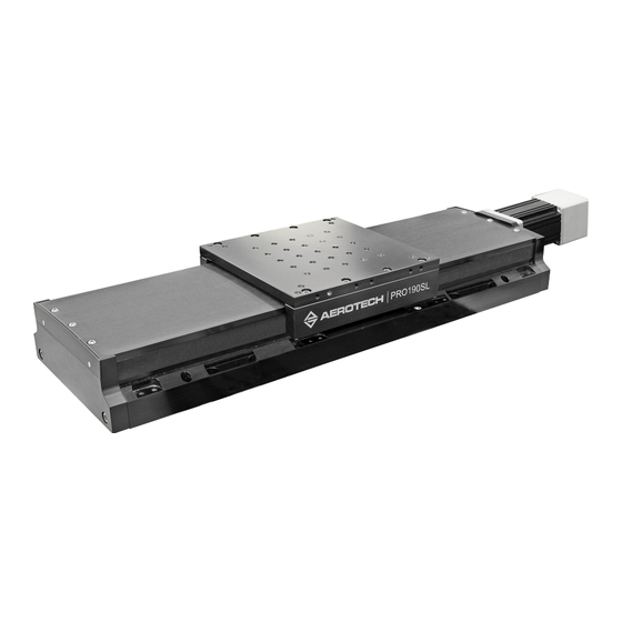
Aerotech PRO190SLE Series Hardware Manual (74 pages)
Mechanical Bearing, Ball-Screw Stage
Brand:
Aerotech
| Category:
Industrial Equipment
| Size: 11 MB
Table of Contents
PRO190SL and SLE Mechanical Bearing, Ball-Screw Stage
1
Table of Contents
3
List of Figures
4
List of Tables
5
EU Declaration of Incorporation
6
UKCA Declaration of Incorporation
7
Safety Procedures and Warnings
8
Installation and Operation
9
Electrical Warnings
10
Motor-Related Warnings
11
Pinch Points
12
Handling and Storage
13
Chapter 1: Overview
15
Table 1-1: Model Numbers and Ordering Options
15
Environmental Specifications
17
Table 1-2: Environmental Specifications
17
Accuracy and Temperature Effects
18
Basic Specifications
19
Table 1-3: PRO190SL/SLE Series Specifications (-050 to -250)
19
Table 1-4: PRO190SL/SLE Series Specifications (-300 to -800)
20
Vacuum Operation
21
Chapter 2: Installation
23
Dimensions
23
Figure 2-1: PRO190SL Dimensions
23
Figure 2-2: PRO190SL Tabletop Dimensions (-TT2/-TT3 Option)
24
Figure 2-3: PRO190SLE Dimensions
25
Figure 2-4: PRO190SLE Tabletop Dimensions (-TT3)
26
Figure 2-5: Z-Axis Bracket Dimensions
27
Securing the Stage to the Mounting Surface
28
Table 2-1: Stage Mounting Surface Flatness Requirement
28
Table 2-2: Stage to Mounting Surface Hardware
28
Attaching the Payload to the Stage
29
Table 2-3: Payload Mounting Surface Flatness Requirement
29
Figure 2-6: Stage Orientations
30
Figure 2-7: Cantilevered Load Capability
31
Figure 2-8: Load Torque Equation
31
Figure 2-9: Torque Required to Turn Ball Screw in Vertical Orientation
31
Chapter 3: Electrical Installation
33
Motor and Feedback Connectors
34
Table 3-1: Brushless Motor Connector Pinout
35
Table 3-2: Mating Connector Part Numbers for the Brushless Motor Connector
35
Table 3-3: Brushless Motor Feedback Connector Pinout
36
Table 3-4: Mating Connector Part Numbers for the Brushless Motor Feedback Connector
36
Table 3-5: Linear Encoder Connector Pinout (-SLE Only)
37
Table 3-6: Mating Connector Part Numbers for the Encoder Connector
37
Table 3-7: Limit Connector Wiring
38
Table 3-8: Mating Connector Part Numbers for the Limit Connector
38
Motor and Feedback Wiring
39
Figure 3-1: Brushless Motor and Feedback Wiring [-SL Option]
39
Figure 3-2: Brushless Motor and Feedback Wiring [-SLE Option]
40
Motor and Feedback Specifications
41
Table 3-9: Hall-Effect Sensor Specifications
41
Table 3-10: Thermistor Specifications (BMS Motor Options)
41
Table 3-11: Encoder Specifications
41
Table 3-12: Rotary Encoder Resolution Specifications
41
Table 3-13: Linear Encoder Resolution Specifications
42
Table 3-14: Limit Switch Specifications
42
Table 3-15: Brake Specifications
42
Table 3-16: PRO190SL/SLE Motor Specifications (BMS100)
43
Table 3-17: PRO190SL/SLE Motor Specifications (BM130)
44
Limits, Marker, and Machine Direction
45
Figure 3-3: Machine Direction
45
Motor and Feedback Phasing
46
Figure 3-4: Hall Phasing Diagram
46
Figure 3-5: Encoder Phasing Reference Diagram (Standard/Square Wave)
47
Figure 3-6: Digital Encoder Phasing Reference Diagram (Sine Wave)
47
Chapter 4: Maintenance
49
Service and Inspection Schedule
49
Cleaning and Lubrication
50
Figure 4-1: Hardcover Rear End Plate Removal
52
Figure 4-2: Hardcover Screw Removal
52
Figure 4-3: Hardcover Removal
53
Motor Mounting
54
Figure 4-4: Motor Mounting Overview
54
Table 4-1: Hardware Requirements
54
Figure 4-5: Attach the Coupling Adapter to the Motor Shaft
55
Figure 4-6: Attach the Motor the Stage
55
Figure 4-7: Tighten the Shaft Coupling to the Drive Screw
56
Side Seal Belt Replacement
57
Table 4-2: Side Seal Belt Replacement Kit Ordering Guide
57
Figure 4-8: Belt Removal at the Attachment Pins
58
Figure 4-9: Spring Location Detail
59
Figure 4-10: Pull through Method
60
Figure 4-11: Stage Table Cover Plate Removal
61
Figure 4-12: Manual Feed Method
62
Figure 4-13: Belt Wrap
62
Figure 4-14: Belt Alignment
63
Figure 4-15: Belt Trim
64
Foldback Motor Belt Adjustment
65
Figure 4-16: Foldback Motor Cover Removal
66
Figure 4-17: Foldback Motor Part Callouts
67
Figure 4-18: Lubricate the Pulley Flanges
67
Troubleshooting
68
Appendix A: Warranty and Field Service
69
Appendix B: Revision History
71
Index
73
Advertisement
Aerotech PRO190SLE Series Hardware Manual (62 pages)
Mechanical Bearing, Ball-Screw Stage
Brand:
Aerotech
| Category:
Industrial Equipment
| Size: 3 MB
Table of Contents
PRO190SL and SLE Mechanical Bearing, Ball-Screw Stage
1
Table of Contents
3
List of Figures
4
List of Tables
5
Safety Procedures and Warnings
7
EU Declaration of Incorporation
11
Chapter 1: Overview
13
Table 1-1: Model Numbers and Ordering Options
13
Environmental Specifications
15
Accuracy and Temperature Effects
15
Table 1-2: Environmental Specifications
15
Basic Specifications
16
Table 1-3: PRO190SL/SLE Series Specifications (-050 to -250)
16
Table 1-4: PRO190SL/SLE Series Specifications (-300 to -800)
17
Vacuum Operation
18
Chapter 2: Installation
19
Unpacking and Handling the Stage
19
Figure 2-1: Lifting Features
20
Dimensions
21
Figure 2-2: PRO190SL Dimensions
21
Figure 2-3: PRO190SLE Dimensions
22
Figure 2-4: Tabletop Accessory Dimensions (-TT3 Option)
23
Figure 2-5: Z-Axis Bracket Dimensions
24
Securing the Stage to the Mounting Surface
25
Table 2-1: Stage Mounting Surface Flatness Requirement
25
Table 2-2: Stage to Mounting Surface Hardware
25
Attaching the Payload to the Stage
26
Figure 2-6: Stage Orientations
27
Figure 2-7: Cantilevered Load Capability
27
Figure 2-8: Load Torque Equation
28
Figure 2-9: Torque Required to Turn Ball Screw in Vertical Orientation
28
Chapter 3: Electrical Installation
29
Motor and Feedback Connectors
30
Table 3-1: Brushless Motor Connector Pinout
31
Table 3-2: Mating Connector Part Numbers for the Brushless Motor Connector
31
Table 3-3: Brushless Motor Feedback Connector Pinout
32
Table 3-4: Mating Connector Part Numbers for the Brushless Motor Feedback Connector
32
Table 3-5: Linear Encoder Connector Pinout (-SLE Only)
33
Table 3-6: Mating Connector Part Numbers for the Encoder Connector
33
Table 3-7: Limit Connector Wiring
34
Table 3-8: Mating Connector Part Numbers for the Limit Connector
34
Motor and Feedback Wiring
35
Figure 3-1: Brushless Motor and Feedback Wiring [-SL Option]
35
Figure 3-2: Brushless Motor and Feedback Wiring [-SLE Option]
36
Motor and Feedback Specifications
37
Table 3-9: Hall-Effect Sensor Specifications (BM or BMS Motor Options)
37
Table 3-10: Thermistor Specifications (BMS Motor Options)
37
Table 3-11: Encoder Specifications
37
Table 3-12: Limit Switch Specifications
37
Table 3-13: Brake Specifications
37
Table 3-14: PRO190SL/SLE Motor Specifications (BMS100)
38
Table 3-15: PRO190SL/SLE Motor Specifications (BM130)
39
Table 3-16: Rotary Encoder Specifications for PRO190SL/SLE Stages
40
Table 3-17: Linear Encoder Specifications for PRO190SL/SLEE Stages
40
Limits, Marker, and Machine Direction
41
Figure 3-3: Machine Direction
41
Motor and Feedback Phasing
42
Figure 3-4: Hall Phasing Diagram
42
Figure 3-5: Encoder Phasing Reference Diagram (Standard/Square Wave)
43
Figure 3-6: Encoder Phasing Reference Diagram (Analog/Sine Wave)
43
Chapter 4: Maintenance
45
Service and Inspection Schedule
45
Cleaning and Lubrication
46
Figure 4-1: Hardcover Rear End Plate Removal
48
Figure 4-2: Hardcover Screw Removal
48
Figure 4-3: Hardcover Removal
49
Motor Mounting
50
Figure 4-4: Motor Mounting Overview
50
Table 4-1: Hardware Requirements
50
Figure 4-5: Attach the Coupling Adapter to the Motor Shaft
51
Figure 4-6: Attach the Motor the Stage
51
Figure 4-7: Tighten the Shaft Coupling to the Drive Screw
52
Belt Adjustment
53
Figure 4-8: Foldback Motor Cover Removal
54
Figure 4-9: Foldback Motor Part Callouts
55
Figure 4-10: Lubricate the Pulley Flanges
55
Troubleshooting
56
Appendix A: Warranty and Field Service
57
Appendix B: Revision History
59
Index
61
Aerotech PRO190SLE Series Hardware Manual (58 pages)
Brand:
Aerotech
| Category:
Industrial Equipment
| Size: 5 MB
Table of Contents
PRO190SL/SLE Hardware Manual
1
Table of Contents
3
List of Figures
4
List of Tables
5
Safety Procedures and Warnings
6
EU Declaration of Incorporation
7
Chapter 1: Overview
9
Table 1-1: Model Numbers and Ordering Options
9
Environmental Specifications
11
Accuracy and Temperature Effects
11
Table 1-2: Environmental Specifications
11
Basic Specifications
12
Table 1-3: PRO190SL/SLE Series Specifications (-050 to -250)
12
Table 1-4: PRO190SL/SLE Series Specifications (-300 to -800)
13
Vacuum Operation
14
Chapter 2: Installation
15
Unpacking and Handling the Stage
15
Figure 2-1: Lifting Features
16
Dimensions
17
Figure 2-2: SL Dimensions
17
Figure 2-3: SLE Dimensions
18
Figure 2-4: PRO190SL/SLE Accessory Tabletop Dimensions (-TT3/-TT6 Option)
19
Figure 2-5: PRO190SL/SLE Z-Axis Bracket Dimensions
20
Securing the Stage to the Mounting Surface
21
Table 2-1: Stage Mounting Surface Flatness Requirement
21
Figure 2-6: Mounting Hole Locations
22
Table 2-2: Stage to Mounting Surface Hardware
22
Attaching the Payload to the Stage
23
Figure 2-7: Cantilevered Load Capability
24
Figure 2-8: Stage Orientations
24
Figure 2-9: Load Torque Equation
25
Figure 2-10: Torque Required to Turn Ball Screw in Vertical Orientation
25
Chapter 3: Electrical Installation
27
Motor and Feedback Connectors
28
Table 3-1: Motor Connector Pinout
29
Table 3-2: Part Numbers for the Motor Connector
29
Table 3-3: Feedback Connector Pinout
30
Table 3-4: Part Numbers for the Feedback Connector
30
Table 3-5: Linear Encoder Connector Pinout (-SLE Only)
31
Table 3-6: Part Numbers for the Encoder Connector
31
Table 3-7: Limit Connector Pinout
32
Table 3-8: Part Numbers for the Limit Connector
32
Motor and Feedback Wiring
33
Figure 3-1: Motor and Feedback Wiring (-SL Option)
33
Figure 3-2: Motor and Feedback Wiring (-SLE Option)
34
Motor and Feedback Specifications
35
Table 3-9: Feedback Specifications
35
Table 3-10: PRO190SL/SLE Motor Specifications (BMS100)
36
Table 3-11: Pro190Sl/Slemotor Specifications (BM130)
37
Table 3-12: Rotary Encoder Specifications for PRO190SL Stages
38
Table 3-13: Linear Encoder Specifications for PRO190SLE Stages
38
Limits, Marker, and Machine Direction
39
Figure 3-3: Machine Direction
39
Motor and Feedback Phasing
40
Figure 3-4: Hall Phasing
40
Figure 3-5: Analog Encoder Phasing Reference Diagram
41
Figure 3-6: Encoder Phasing Reference Diagram (Standard)
41
Chapter 4: Maintenance
43
Service and Inspection Schedule
43
Cleaning and Lubrication
44
Figure 4-1: Hardcover Removal Procedure (Step 2)
46
Figure 4-2: Hardcover Removal Procedure (Step 3)
46
Figure 4-3: Hardcover Removal Procedure (Step 4)
47
Belt Adjustment
48
Figure 4-4: Foldback Motor Cover Removal
49
Figure 4-5: Foldback Motor Part Callouts
50
Figure 4-6: Lubricate the Pulley Flanges
50
Troubleshooting
51
Appendix A: Warranty and Field Service
53
Appendix B: Revision History
55
Index
57
Advertisement
Advertisement
Related Products
Aerotech PRO190SLE-050
Aerotech PRO190SLE-100
Aerotech PRO190SLE-150
Aerotech PRO190SLE-200
Aerotech PRO190SLE-250
Aerotech PRO190SLE-300
Aerotech PRO190SLE-400
Aerotech PRO190SLE-500
Aerotech PRO190SLE-600
Aerotech PRO190SLE-800
Aerotech Categories
Industrial Equipment
DC Drives
Controller
Engine
Amplifier
More Aerotech Manuals
Login
Sign In
OR
Sign in with Facebook
Sign in with Google
Upload manual
Upload from disk
Upload from URL