
Related Manuals for Alfa Laval S946


Summary of Contents for Alfa Laval S946
- Page 1 MAN Diesel & Turbo MANAGUA Order No.: 4500968861 Al Order No.: 84.6893.31 MAN Material: 11.63010-0244...
- Page 2 Process Data Sheets Safety S and P Flex Separation System Description Operating Instructions Parameter List Alarms and Fault Finding Installation System Reference Separator Manual Marine & Diesel Equipment With Spare Parts Catalogue Anncillary Components With Spare Parts Catalogue Printed June 2008 Document No.
- Page 3 MAN Diesel & Turbo SE D-86224 Augsburg Process data Lubeoil Separator type S946 Delivery as Flex Modules Order Managua December 16 , 2014...
- Page 4 General ALCAP -System ● ALCAP was specially developed for cleaning of heavy fuel oils ● Max. density of the oils to be cleaned 1.010 kg/m³ at 15 °C ● Combination of purifier and clarifier within one machine, thus no more series arrangement of a purifier followed by a clarifier necessary ●...
- Page 5 50°C separation temperature 95°C at normal conditions max. effective capacity 5.000 l/h colour C3, RAL 9002 Separator type S946 quantity separation principle ALCAP discharge system centrishoot clean oil discharge pressure 3.0 bar electric motor, IE2 11,0 kW...
- Page 6 Electrical supply voltage / frequency 440 V, 60 Hz control voltage 230 V valve operating voltage 24 V Operating water < 180 g Ca CO3, 10° dH Hardness chloride ions <100 ppm NaCl pH- value 6,5 - 9 suspended matter max 10 ppm max.
- Page 7 ABB Motors Technical Data Sheet - DOL and Generators Project Location Department/Author Customer name Customer ref. Item name 3GAA131315-KDEAL1 Our ref. Rev/Changed by Date of issue Saving ident Pages 31-10-2011 Definition Data Unit Remarks Product TEFC, 3-phase, squirrel cage induction motor Product code 3GAA131315-KDEAL1 Type/Frame...
- Page 8 ABB Motors Technical Data Sheet - DOL and Generators Project Location Department/Author Customer name Customer ref. Item name 1,00001 Our ref. Rev/Changed by Date of issue Saving ident Pages 21.11.2012 untitled.xls 1(3) Definition Data Unit Remarks Product TEFC, 3-phase, squirrel cage induction motor Product code 3GAA 102 213-BSE Type/Frame...
- Page 9 1 operating data 2 &ND&Field1051744:VI&Field1051745:Auslegung&Field64:20.09.2012&Field1051747:148414&Field1056706:0010&Field1: Version: 14.4.1 COPY RIGHT by KRAL subject to change (04/2013) Alfa Laval Kolding A/S, P O Box 802, 6000 Kolding, Denmark; Tel.: +45 79 32 22 00 17. Dezember 2014 www.alfalaval.com, E-mail: info.dk@alfalaval.com...
- Page 11 S and P Flex Separation Safety Printed Feb 2008 Book No. 584610-02 V 1...
- Page 12 Alfa Laval reserves the right to make changes at any time without prior notice. Any comments regarding possible errors and omissions or suggestions for improvement of this publication would be gratefully appreciated. Copies of this publication can be ordered from your local Alfa Laval company.
- Page 13 (type of liquid, rotational speed, temperature, density, etc.). The system must be used for this function only, and strictly within Alfa Laval´s specifications. Incorrect operation or maintenance may result in a heavy unbalance, reduction of material strength, etc.
- Page 14 Clean the operating system regularly to avoid sludge discharge malfunction. Ensure that personnel are fully trained and competent in installation, operation, maintenance, and emergency procedures. Use only Alfa Laval genuine spare parts and the special tools supplied. 584610-02...
- Page 15 S AND P FLEX SEPARATION SAFETY 1 SAFETY INSTRUCTIONS 1.2 Warning Sign Definitions Below are definitions of the warning signs used. Danger – serious injury or death Example: This type of safety sign or instruction indicates an imminently hazardous situation which, if not avoided, will result in death or serious injury.
- Page 16 1 SAFETY INSTRUCTIONS S AND P FLEX SEPARATION SAFETY 1.3 Summary of Safety Hazards Below follows a selection of the warnings which have been used in the text of this instruction manual to ensure safe installation, start-up, operation, stop, and maintenance. Further warnings are to be found in the appropriate places throughout the manual.
- Page 17 S AND P FLEX SEPARATION SAFETY 1 SAFETY INSTRUCTIONS Use the separation system for the purpose, and within the limits, specified by Alfa Laval. Failure to do so could cause a violent breakdown. If power cable polarity has been reversed, the separator will rotate in reverse, and vital rotating parts can loosen.
- Page 18 After an emergency stop, the cause of the fault must be identified. If all parts have been checked and the cause not found, contact Alfa Laval for advice before restarting the separator. Burning hazard Lubricating oil and various machine surfaces can be hot and cause burns.
- Page 19 S AND P FLEX SEPARATION SAFETY 1 SAFETY INSTRUCTIONS Breakdown hazard Never reset an alarm without first finding and remedying the cause. Disintegration hazard Do not discharge a vibrating separator. Vibration can increase if solidified sludge is only partially discharged. Burn hazard Avoid contact with hot surfaces.
- Page 20 1 SAFETY INSTRUCTIONS S AND P FLEX SEPARATION SAFETY Stop Breakdown hazard Stop the separator by means of the control unit, and not by turning off the motor. Never attempt to clean the bowl by manual discharge in connection with stop. Emergency stop Disintegration hazard If unusually strong vibration occurs, press the...
- Page 21 S AND P FLEX SEPARATION SAFETY 1 SAFETY INSTRUCTIONS After emergency stop Entrapment hazard Make sure that rotating parts have come to a complete standstill before starting any dismantling work. The rotation indicator lamp, where applicable, must be off. Entrapment hazard To avoid accidental start, switch off and lock power supply before starting any dismantling work.
- Page 22 1 SAFETY INSTRUCTIONS S AND P FLEX SEPARATION SAFETY Disintegration Hazards Separator parts that are either missing, worn beyond their safe limits or incorrectly assembled, may cause severe damage or fatal injury. Burn and Corrode Hazards Escaping hot and/or corroding process material, which can be hazardous, may still remain in the separator after stop.
- Page 23 S AND P FLEX SEPARATION SAFETY 1 SAFETY INSTRUCTIONS Risk for eye injury from flying seal ring parts The seal ring breaks when removed from the bowl hood. Crush hazard The distributor and disc stack can adhere to the top disc.
- Page 24 1 SAFETY INSTRUCTIONS S AND P FLEX SEPARATION SAFETY Crush hazard Do not rotate the spindle assembly during lifting. The spindle assembly may otherwise come loose from the lifting tool. Risk for eye injury from flying snap ring Use the correct pliers for dismantling of snap ring to avoid accidental release.
- Page 25 Max. 0,2 mm Disintegration hazards Always contact your Alfa Laval representative if you suspect that the depth of the corrosion damage exceeds 0.5 mm (0.2 mm for bowl body and bowl hood) or if cracks have been found. Do not...
- Page 26 1 SAFETY INSTRUCTIONS S AND P FLEX SEPARATION SAFETY Disintegration hazard Erosion damage weakens parts by reducing the thickness of the material. Pay special attention to the pillars between the sludge ports in the bowl wall. Replace parts if erosion is suspected of affecting strength or function.
- Page 27 S AND P FLEX SEPARATION SAFETY 1 SAFETY INSTRUCTIONS Crush hazard The ring on the lifting tool must be pushed home against the discharge slide, otherwise it may come loose from the tool. The number of discs may have to be increased to adjust the disc stack pressure.
- Page 28 Failure to do so may lead to breakdown. Cleaning in place Health Risk Do not forget to disconnect the CIP equipment and re-connect connections. Use only Alfa Laval recommended CIP liquids. 584610-02...
- Page 29 S AND P FLEX SEPARATION SAFETY 1 SAFETY INSTRUCTIONS 1.4 Optional Heaters 1.4.1 CBM heaters Burn Hazard The heater must not be used without the insulated protection cover. This shields the hot surfaces and also acts as a safety cover in the unlikely event of leakage.
- Page 30 1 SAFETY INSTRUCTIONS S AND P FLEX SEPARATION SAFETY 1.4.2 Electric heaters Electrocution Risk Switch off the main power before opening the heater junction box, or dismantling the heater. It is very important that the correct heater element is installed. 584610-02...
- Page 31 S Flex Separation System Description Printed Jul 2010 Book No. 584621-02 V3...
- Page 32 Alfa Laval reserves the right to make changes at any time without prior notice. Any comments regarding possible errors and omissions or suggestions for improvement of this publication would be gratefully appreciated. Copies of this publication can be ordered from your local Alfa Laval company.
-
Page 33: Table Of Contents
Contents System Overview ........................... Oil Flow............................1 System Layout .......................... 2 System Components ....................... 4 The Process ............................Principle ............................5 Process Cycle Start........................6 Discharge ............................. 8 Increased Water Content ....................... 9 584621-02... - Page 34 584621-02...
-
Page 35: System Overview
S FLEX SEPARATION SYSTEM DESCRIPTION 1 SYSTEM OVERVIEW 1 System Overview The S-Type Separation System is designed for Cleaned oil leaves the separator through the oil cleaning of fuel and lube oils for diesel engines, outlet while separated water and sludge and fuel oil for gas turbine engines, in marine accumulate at the periphery of the rotating and power applications. -
Page 36: System Layout
1 SYSTEM OVERVIEW S FLEX SEPARATION SYSTEM DESCRIPTION 1.2 System Layout Heater Temperature Pressure transmitter, Pneumatically controlled Separator transmitter (TT1, oil (PT1) change-over valve (V1) Heats unprocessed Cleans the oil by TT2) oil to separation removing water Measures the pressure Directs the unprocessed oil to temperature. - Page 37 S FLEX SEPARATION SYSTEM DESCRIPTION 1 SYSTEM OVERVIEW Regulating valve (RV4) Control unit Pressure transmitter, oil Water transducer (MT60) (PT4) To manually regulate the Supervises the separation Measures change in water backpressure in the system. content in the cleaned oil, Measures the pressure in clean oil outlet.
-
Page 38: System Components
1 SYSTEM OVERVIEW S FLEX SEPARATION SYSTEM DESCRIPTION 1.3 System Components EPC 60 Control unit and starter Safety valve SV10A (Lube oil only) EPC 60 Control unit Water Operating transducer (MT60) Operating water Change-over valve (V1) Combined regulating valve (RV4) and shut-off valve (V4) Clean oil outlet... -
Page 39: The Process
S FLEX SEPARATION SYSTEM DESCRIPTION 2 THE PROCESS 2 The Process 2.1 Principle During the separation process, sludge and water accumulate at the periphery of the separator bowl. Sludge and water Sludge and water are discharged at preset time intervals. During discharge, the oil inlet is closed. -
Page 40: Process Cycle Start
2 THE PROCESS S FLEX SEPARATION SYSTEM DESCRIPTION 2.2 Process Cycle Start First the oil pump, separator, and heater are Controller started. The temperature transmitter (TT) and the speed transmitter (ST) signal the EPC-60 control unit continuously. When the correct separator speed and the correct temperature are reached, a sludge discharge is carried out to ensure the bowl is empty. - Page 41 S FLEX SEPARATION SYSTEM DESCRIPTION 2 THE PROCESS Using the flow rate calculated in paragraph 2 Controller above, the control unit signals the solenoid valve to open so that the correct amount of conditioning water is added to the separator bowl.
-
Page 42: Discharge
2 THE PROCESS S FLEX SEPARATION SYSTEM DESCRIPTION 2.3 Discharge The separator discharges after a preset time has elapsed. The following sequence takes place: The change-over valve changes to oil Controller recirculation. Using the flow rate calculated in paragraph 2 under 2.2 Process Cycle Start, page 6, the... -
Page 43: Increased Water Content
S FLEX SEPARATION SYSTEM DESCRIPTION 2 THE PROCESS 2.4 Increased Water Content If the water transducer senses increased water content in the oil, the following takes place: The water drain valve (V5) opens for a Controller number of seconds. The water drain valve closes again, and the transducer signal is evaluated. - Page 44 2 THE PROCESS S FLEX SEPARATION SYSTEM DESCRIPTION 584621-02...
- Page 45 S and P Flex Separation Operating instructions Printed 03-2014 Book No. 584612-02, rev. 8...
- Page 46 Telephone: +46 8 530 650 00 Telefax: +46 8 530 310 40 © Alfa Laval Tumba AB 03-2014 The original instructions are in English This publication or any part there of may not be reproduced or transmitted by any process or means without prior written permission of Alfa Laval Tumba AB.
- Page 47 Contents Operating Before First Startup Control Panel Manual Start from Standstill Automatic Start from Standstill During Separation Stop Emergency Stop After Emergency Stop Separator Emergency Operation 1.10 Cleaning In Place 1.10.1 CIP Start 1.10.2 CIP Running 1.10.3 CIP Stop 1.11 Check if separator bowl is clogged 1.12 Intervals Between Sludge Discharges...
- Page 48 1.17 Operation without all sensors (Emergency operation) 1.17.1 System Without Speed Sensor 1.17.2 System Without Vibration Sensor 1.17.3 System Without Cover Switch 1.17.4 System With PT1 Disabled 1.17.5 System With PT4 Disabled 1.17.6 System With PT5 Disabled (S-separator only) 1.17.7 System With TT1/TT2 Disabled 1.17.8 Control of Sludge Pump, Level in Sludge Tank, and Butterfly Valve 1.17.9 System Without Feed Pump...
-
Page 49: Operating
1 Operating Before First Startup The Control Panel must be configured to suit the system components. Check that the separator is correctly assembled and connected to power supply of correct voltage and frequency. The control panel must be ON. Breakdown hazard Assemble the separator completely before start. - Page 50 1 Operating Use the separation system for the purpose, and within the limits, specified by Alfa Laval. Failure to do so could cause a violent breakdown. Check the oil sump level. If necessary, top up until oil starts to run from the oil-filling hole.
- Page 51 1 Operating Operating Water Pressure Check that the operating water pressure is sufficient (200 – 800 kPa or 2 – 8 Bar). The LEDs on the water block and connectors indicate that the valve has power on. They do not indicate if the valve is clogged (an alarm is given if this is the case).
-
Page 52: Control Panel
1 Operating Control Panel To start the Control Panel, switch on the main power switch on the control cabinet. General The Control Panel has three main lists. • Operation • Alarms • Setting Operation List To access the Operation List at any time during the operation process press the ‘Return button’... - Page 53 1 Operating At any time during operation, the operator can initiate a STOP sequence by pressing the ‘Stop’ button. REMOTE DISCHARGE HEATER SEPARATOR CONTROL FEED SLUDGE CLEANING PUMP PUMP IN PLACE X023920A If control panel black screen appear. See “Alarms & Fault finding” manual.
-
Page 54: Manual Start From Standstill
1 Operating Manual Start from Standstill Press the ‘Start’ button. The operator can select to start the system manually by setting parameter P130 to ‘stepwise’. First start-up is always manual and not dependant on P130 setting. REMOTE HEATER DISCHARGE SEPARATOR CONTROL A rotation test must be carried out using the I/O test FEED... - Page 55 1 Operating If the power has been off and/or the separator bowl cover has been removed a number of questions which have to be answered before the system can be started are shown on the display: ‘Has the bowl been dismantled? YES, NO’ (S-type separator only) Use the ‘arrow’...
- Page 56 1 Operating Start The feed pump (if installed) starts. The LED on the start button flashes, the LED for the feed pump lights, and text ‘Starting feed pump’ shows on the display. The start button LED shines steadily and the display shows either ‘To start heater, press start button’, or ‘To start separator, REMOTE DISCHARGE...
- Page 57 1 Operating Press the start button a second time. The heater (if installed) starts. The LED on the start button flashes, the LED for the heater lights, and text “Starting heater” shows on the display. Wait for increasing temperature. REMOTE DISCHARGE HEATER SEPARATOR...
- Page 58 1 Operating Press the start button a third time. The separator motor starts. The LED on the start button flashes, the LED for the separator lights, and text ‘Starting separator’ shows on the display. Wait for speed feedback (if speed sensor REMOTE DISCHARGE HEATER...
- Page 59 1 Operating Press the start button a fourth time. If the feed temperature is below the value in P184, the controller stays in RECIRCULATION mode. The LED on the start button flashes, and text ‘Waiting in RECIRCULATION for separation temperature’ shows on the display. REMOTE DISCHARGE HEATER...
- Page 60 1 Operating Start S-type separator start sequence START command Has the bowl been dismantled? Assembled according STANDSTILL to manual? Bowl cleaned? Proceed without calibration * local or remote **, auto ** or stepwise start possible Proceed with calibration * Change to local stepwise SEPARATION start only...
- Page 61 1 Operating Start P-type separator start sequence START command Assembled according to STANDSTILL manual? Proceed with start sequence local start only...
-
Page 62: Automatic Start From Standstill
1 Operating Automatic Start from Standstill The operator can select to start the system automatically by setting parameter P130 to ‘automatic’. The control panel automatically goes through the same procedure as described under Manual Start from Standstill. If the bowl has not been dismantled or cleaned, the previously calculated filling time (parameter P233) is used, a discharge sequence and a bowl leakage/water transducer test are run, and... -
Page 63: During Separation
1 Operating During Separation Observe information on the control panel display. The times in each sequence are shown in the bottom left-hand corner of the display Breakdown hazard If strong vibration occurs, press the emergency stop button and evacuate the room. Never discharge a vibrating separator. - Page 64 1 Operating Discharge sequences run automatically at preset intervals (timer P220). Discharge sequence can also be run manually by pressing the ‘Discharge’ button. REMOTE HEATER SEPARATOR CONTROL FEED CLEANING PUMP IN PLACE X023923A...
- Page 65 1 Operating The Sludge Pump runs during discharge or when there is high level in the sludge tank, or can be started manually by pressing the ‘Sludge Pump’ button on the control panel. Do not run the sludge pump longer than necessary. If REMOTE DISCHARGE HEATER...
-
Page 66: Stop
1 Operating Stop Breakdown hazard Stop the separator by means of the control unit, and not by turning off the power. Never attempt to clean the bowl by manual discharge in connection with stop. To stop the system: The operator can stop the system when in the ‘START’, RECIRCULATION’, or ‘SEPARATION’... - Page 67 1 Operating • The separator motor is turned off and the stop timer starts running. At the same time, the heater is turned off (see 1.13.4 Heater shut down on page 42. The system waits for the feed temperature and speed to decrease. •...
-
Page 68: Emergency Stop
1 Operating Emergency Stop Disintegration hazard If an emergency situation or unusually strong vibration occurs, press the Emergency Stop button and evacuate the room. X024579A If oil spray, feed pump is stopped by emergency stop button. Do not enter the room after an emergency stop while the separator is still rotating. -
Page 69: After Emergency Stop
1 Operating After Emergency Stop Separator standstill Dismantling work must not be started before all rotating parts have come to a complete standstill. Entrapment hazard Make sure that rotating parts have come to a complete standstill before starting any dismantling work. The rotation indicator lamp, where applicable, must be off. - Page 70 1 Operating Separator reassembled The separator must be fully reassembled with all covers and guards in place and tightened before unlocking the power supply and starting the system. Breakdown hazard Assemble the separator completely before restart. All couplings, covers, and guards must be in place and properly tightened.
-
Page 71: Separator Emergency Operation
1 Operating Separator Emergency Operation If the Control System has a total failure, the Separator and Feed Pump can be run manually. Jumpers or pushbuttons can be connected between terminals X1:113 - 114 (for separator) and X1:115 - 116 (for feed pump). Separator and Feed Pump will start immediately when these terminals are bridged, but can be stopped with the Emergency Stop pushbutton. -
Page 72: Cleaning In Place
1 Operating 1.10 Cleaning In Place The use of Cleaning In Place (CIP) equipment is recommended for best separation results. For further information on the CIP equipment, see the CIP booklet, bookno. 1817261. 1.10.1 CIP Start CIP can be selected from STAND STILL only, and only from a local control panel. - Page 73 1 Operating Connect hoses for CIP liquid before pressing “start” button. With CIP selected from STAND STILL, press the ‘START’ button to start the separator motor. The motor starts unless the system prevents start, or alarms are active. Wait for speed feedback. REMOTE DISCHARGE HEATER...
-
Page 74: Cip Running
1 Operating 1.10.2 CIP Running When the bowl has reached normal speed, a bowl closing procedure will be performed. While the CIP system is running, closing water valve SV16 opens for 2 seconds and closes for the time set in parameter P228 (pulse interval) repeatedly. -
Page 75: Cip Stop
1 Operating 1.10.3 CIP Stop Stop the CIP process by pressing the ‘Stop’ button on the control panel. The CIP process can be restarted. • The separator motor is turned off. Alarm delay (3 minutes) starts, and stop timer starts. If the speed limit in parameter P180 (alarm limit bowl speed low) is not reached within 3 minutes, alarm ‘A9 Bowl speed high REMOTE... - Page 76 1 Operating Health Risk Do not forget to disconnect the CIP equipment and re-connect the process connections.
-
Page 77: Check If Separator Bowl Is Clogged
1 Operating 1.11 Check if separator bowl is clogged Valid for Purifiers (not Alcap or Clarifiers) Purifiers have no automatic indication if the bowl is clogged or filled with too much solids. Recommendation is to check each Bunker analyze report and determine if there is any risk for a higher than normal sludge production. -
Page 78: Heater Control (Optional)
1 Operating 1.13 Heater Control (optional) The temperature in the feed inlet is normally supervised via TT1, and can be controlled by a heater via TT2. Supervision and control are active even if one of the sensors is disabled. TT2 can be used by the customer; no alarm is given. - Page 79 1 Operating Example: P123 = 30, P126 = 40 results in a P-band of 0.40 x 30 = 12 as long as the temperature is below P125.
-
Page 80: Control Of The Electric Heater (Optional)
1 Operating 1.13.1 Control of the electric heater (optional) P119 = electric. The following parameters should not be displayed in the parameter list: P121, P122. Five outputs and one input are used to control the electric heater: • three relay outputs to up to three fixed power steps depending on the heater size (P120) •... -
Page 81: Control Of The Cbm Heater (Optional)
1 Operating It is important that the fixed power steps are working continuously when activated. Use an established method e.g. delay drop out. As a new output signal is calculated every second, the variable load output is activated for parts (0.1) of a second. 0.1 s activates 1/10 of the available power on the output = 1.6 kW. -
Page 82: If Heater Not Controlled Or External
1 Operating The signal to the steam valve is pulsed with an on-time corresponding to the temperature controller output. Example: output = +50% means the increment steam valve output is activated for 0.50 s/s. When the heater is stopped, the decrement steam valve signal is on for the time set in P121. -
Page 83: Cross Connection/Serial Operation
1 Operating 1.14 Cross connection/serial operation Valid for P-type separators It might be desirable to cross-connect two separator modules, or operate them in series. For that purpose the EPC60:s must be able to communicate via Ethernet. 1.14.1 Set up communication The EPC60:s may communicate over any customer defined network or be connected directly to each other... -
Page 84: Cross Connection
1 Operating 1.14.3 Cross connection One separator module can use the feed pump and heater of the other one. • P145 is set to “cross master” in the system which separator is used. The heater/feed pump of this system is automatically disabled. -
Page 85: Programmable Inputs And Outputs
1 Operating 1.15 Programmable Inputs and Outputs An extra I/O kit is available as an option. This kit contains two boards, one with six programmable digital inputs and one with six progammable relay outputs. The customer can select an optional function for each of these inputs and outputs from a list of alternatives (see below). -
Page 86: Common Alarm Indication
1 Operating altId Alternative Comments Remote enabled remote button activated Closed = remote activated Valve in sludge outlet controlled if pneumatic valve, see P131 and Activation diagram Closed = open or close valve (set with P131) Common alarm Alternative Common alarm, Closed = no alarm, also see separate description Indication V1 Position of valve V1, Closed = feed on to separator... -
Page 87: I/O Test Function
1 Operating 1.16 I/O Test Function Activity Reference/Limits If system has active alarms, check and take actions before starting the I/O test. Press button F-step backwards and related arrows up ( C ) Acc. to IB(s) and down ( E ) for Log –in into the I / O test. Follow the list of I/O‘s (item 25-72) to check status of all el. - Page 88 1 Operating SV15 Discharge valve Valid for: Verify the operation of the valve, see also that the green diode All S and P types on the valve connector is lit. SV16 – Closing water valve Valid for: All S and P types Verify the operation of the valve, see also that the green diode on the valve connector is lit.
- Page 89 1 Operating INPUTS Heater fault signal Optional Check that this input is 1 as long as the output “Heater on” is Valid for: activated. If not ok, check settings of over temperature device All S and P types Go back to “Heater on” Item no. 47 and deactivate (0 on display), then go back to this section and verify that “Heater fault”...
- Page 90 1 Operating PT4 – Oil outlet pressure transmitter 4-20mA Input Check that the indication shows approx 0 bar. Valid for: All S and P types Note that if pipes are connected to the system, pressure might not be 0 bar. PT100 input TT1 –...
-
Page 91: Operation Without All Sensors (Emergency Operation)
1 Operating 1.17 Operation without all sensors (Emergency operation) If a sensor is malfunctioning it is possible to disable it temporarily until it can be fixed or replaced. 1.17.1 System Without Speed Sensor It is possible to run the system without speed sensor (P113 = no). -
Page 92: System With Pt1 Disabled
1 Operating Remote start is not allowed. This also applies if the cover switch is disabled (P116 = yes). 1.17.4 System With PT1 Disabled It is possible to run the system with PT1 disabled (P157 = 0). In this case alarms A40 – A42 and A44 are not supervised. -
Page 93: System With Tt1/Tt2 Disabled
1 Operating 1.17.7 System With TT1/TT2 Disabled It is possible to disable one of the temperature sensors TT1 or TT2 with parameter P146. The readings normally taken from the disabled sensor is then replaced with the readings from the other sensor in all sequences. When a temperature transmitter is disabled the corresponding sensor error alarm, A22 or A31, is blocked. -
Page 94: System Without Feed Pump
1 Operating See also the Sequence diagram for other occasions when the sludge pump is activated, if selected (Parameter List chapter ‘2.2 Discharge’) . The separator sludge outlet can contain a manual butterfly valve which is used to close the outlet when the separator is standing still. -
Page 95: System Without Water Transducer (S-Separator Only)
1 Operating 1.17.10 System Without Water Transducer (S-separator only) It is possible to run the system without water transducer (P117 = no). In this case alarms A80 - A85 and A74 are not supervised. There is no calibration of the water flow. In separation, automatic discharges are initiated every 15 minutes (overrides P220). - Page 96 S Flex Separation Parameter List Printed 10-2014 Book No. 584613-02 rev. 8...
- Page 97 Telephone: +46 8 530 650 00 Telefax: +46 8 530 310 40 © Alfa Laval Tumba AB 10-2014 The original instructions are in English This publication or any part there of may not be reproduced or transmitted by any process or means without prior written permission of Alfa Laval Tumba AB.
- Page 98 Contents Parameter list Setting List Operation Modes Change-over Sequence 2.1.1 Change-over without calibration 2.1.2 Calibration of the water flow via SV10 Discharge...
-
Page 100: Parameter List
1 Parameter list Setting List To access the Setting List at any time during the operation process press the ‘Return button’ repeatedly until the Setting List is reached. Relevant parameters only are shown on the display. REMOTE DISCHARGE HEATER SEPARATOR CONTROL FEED SLUDGE... - Page 101 Save any change by pressing the ‘Enter’ button. REMOTE DISCHARGE HEATER SEPARATOR CONTROL Certain parameters can only be changed by the factory, the chief engineer, or an Alfa Laval service engineer FEED SLUDGE CLEANING PUMP PUMP IN PLACE X023913A...
- Page 102 1 Parameter list Parameter Pass- Denomination Default Unit Min. Max. word value value value level P100 Display language: English English/ German/ Spanish/ French/ Italian/ Portuguese/ Finnish/ Swedish P101 Selection of temp. presentation °C Celsius/Fahrenheit P102 Selection of feed flow rate m3/h presentation m3/h or USG/h P103...
- Page 103 1 Parameter list Parameter Pass- Denomination Default Unit Min. Max. word value value value level P119 Heater installed no/elec- Can be changed tric/steam/external in even in STOP. See also "Control of Heater" in the Operating instructions manual. P120 If P119 = electric: heater size P121 If P119 = steam: steam valve transition time...
- Page 104 1 Parameter list Parame- Pass- Denomination Unit Min. Max. word fault value value level value P133 Optional output 1 (Relay) See also “Programmable P134 Optional output 2 (Relay) in- and outputs” P135 Optional output 3 (Relay) in the Operating instructions P136 Optional output 4 (Relay) manual for all...
- Page 105 1 Parameter list Parame- Pass- Denomination Default Unit Min. Max. word value value value level P163 Alarm limit "A57 Oil leaking from bowl" P164 High oil pressure limit (PT4) during leakage test P165 Low oil pressure limit (PT4) during leakage test P167 Not used P169...
- Page 106 1 Parameter list Parame- Pass- Denomination Default Unit Min. Max. word value value value level P231 30,0 SV15 opening time P232 Draining of operating water P233 Filling time conditioning water (calculated during calibration)xxx (120 initially) P234 Sludge pump additional/manual running time P236 Water drain time during STOP P237...
- Page 107 1 Parameter list Parameters depending on the setting of P111 Separator size (P111, default 0) S 811 S 820 S 400 S 500 S 600 S 700 S 800 S 816 S 825 S 840 S 850 S 860 S 870 S 880 S 200 S 300...
- Page 108 1 Parameter list If P111 = 0 (default value), the operator is automatically forced to go through a system configuration procedure to setup the system.
- Page 109 1 Parameter list Parameters depending on the setting of P112 Oil type (selected with P112) Parame- Pass- Descrip- IF30 HF180 Min. Max. Unit LO TP LO CH word tion IF40 HF380 Trunk Cross value value level IF60 HF460 head IF100 HF600 HF700 P183...
-
Page 110: Operation Modes
2 Operation Modes Change-over Sequence This sequence is run through when the system changes operation mode from RECIRCULATION to SEPARATION after start (supervision similar as in RECIRCULATION). This transition phase may include calibration of the water flow via SV10, if the operator answers “yes”... - Page 111 2 Operation Modes Test of calibration The calibration is repeated at every (P242) discharge. The measured time to fill the bowl is then compared with the saved time used to calculate the SV10 flow rate (the old value is not changed). If the time to fill the bowl has decreased with the relative value in P160, the alarm ‘A131 Sludge in bowl’...
-
Page 112: Discharge
2 Operation Modes Discharge During discharge three different sequences are run through: • displacement sequence (step 1) • discharge sequence (step 2) • bowl leakage/water transducer test (step 3) The following diagram shows the equipment which is activated during the sequences, the activation pattern and the corresponding timers. - Page 113 S Flex Separation Alarms and Fault Finding Printed 07-2014 Book No. 584614-02, rev. 6...
- Page 114 Telephone: +46 8 530 650 00 Telefax: +46 8 530 310 40 © Alfa Laval Tumba AB 07-2014 The original instructions are in English This publication or any part there of may not be reproduced or transmitted by any process or means without prior written permission of Alfa Laval Tumba AB.
- Page 115 Contents Alarms Alarms List Alarm History List Display Alarms and Actions EPC 60 Control panel...
-
Page 117: Alarms
1 Alarms Alarms List To access the Alarms List press the ‘Alarm Button’. The latest 50 alarms are stored in the Alarm History List. See below. REMOTE DISCHARGE HEATER SEPARATOR CONTROL FEED SLUDGE CLEANING PUMP PUMP IN PLACE X023912B Press the arrow buttons to go up or down in the list. - Page 118 1 Alarms For each item in the list you can press the ‘Information’ button for help and information. Press the ‘Information’ button again to return to your previous position. You can also acknowledge and/or reset this alarm. REMOTE DISCHARGE HEATER SEPARATOR CONTROL FEED...
- Page 119 1 Alarms Press the ‘Return’ button to leave the list. REMOTE DISCHARGE HEATER SEPARATOR CONTROL FEED SLUDGE CLEANING PUMP PUMP IN PLACE X023912A...
-
Page 120: Alarm History List
1 Alarms Alarm History List To access the Alarm History List at any time during the operation process press the ‘Return button’ repeatedly until the Alarm History List is reached. Relevant parameters only are shown on the display REMOTE DISCHARGE HEATER SEPARATOR CONTROL... -
Page 121: Display Alarms And Actions
2 Display Alarms and Actions A20-A25 A30-A32 A40-A43 A50-A59 A80-A85 A110-A111 A100-A103 A70-A74 A90-A97 A122 A120-A121 A01 A15 A130 - A139 X024968a Alarm Alarm text Conditions Why? What to do code Feed pump (if P127 = yes) Pump starter failure Delayed by P168. - Page 122 2 Display Alarms and Actions Alarm Alarm text Why? What to do Conditions code Heater, electric (if P119 = electric) Delayed 2s. Separator starter Feedback signal from Check the contactor failure contactor missing. function. Check input terminal in the PLC Temperatur transmitter feed inlet TT1 Delayed by P150.
- Page 123 2 Display Alarms and Actions Alarm Alarm text Why? What to do Conditions code Temperature alarm Reminder only, if P146 sensor disabled = TT1 Temperature increase Delayed by P169. Insufficient heating Check heater too slow Limit in P184. during start. function.
- Page 124 2 Display Alarms and Actions Alarm Alarm text Why? What to do Conditions code Oil backpressure PT4 Delayed by P150. Decreased Check feed pump Alarm limit in P154. throughput and adjust flow. Regulating valve open Adjust back pressure too much valve Change over valve Check air pressure,...
- Page 125 2 Display Alarms and Actions Alarm Alarm text Why? What to do Conditions code Oil leaking from bowl Delayed by P245. Bowl periphery Change seal ring Alarm limit in P163. sealing damaged in bowl hood. Check/change rubber rings and valve plugs. Leakage somewhere Check for leakage.
- Page 126 2 Display Alarms and Actions Alarm Alarm text Why? What to do Conditions code High water content Number of drainings Too much water in Investigate cause and in P187. Limit in P224. oil outlet. remedy. Much water in the Check where the water feed.
- Page 127 2 Display Alarms and Actions Alarm Alarm text Why? What to do Conditions code Bowl speed sensor Delay 4s. Timer stop. Sensor or cable Replace sensor. If error no spare sensor damaged. available, set parameter P179 = 0 to be able to run the system.
- Page 128 2 Display Alarms and Actions Alarm Alarm text Why? What to do Conditions code Vibration sensor separator (if P114 = yes) A100 High vibration warning Delayed by P150. Sludge remaining in Dismantle, clean Alarm limit in P182. part of the bowl and check the bowl before restart.
- Page 129 2 Display Alarms and Actions Alarm Alarm text Why? What to do Conditions code A101 High vibration Delay 1s. Alarm limit Sludge remaining in Dismantle, clean shutdown in P181. and check the bowl part of the bowl before restart. See Service Manual.
- Page 130 2 Display Alarms and Actions Alarm code Alarm text Why? What to do Conditions Frame cover switch separator (if P115 = yes) A110 Frame cover open Delay 1s. Assemble Separator not Start not possible. properly assembled the separator according to instructions.
- Page 131 2 Display Alarms and Actions Alarm code Alarm text Why? What to do Conditions A136 Communication error A137 Cabinet over Reminder only temperature A138 Too many start Contactor activated attempts 5 times within last 60 minutes. A139 Delay 2 s EPC60 internal IO-card status or Check IO cards...
- Page 132 2 Display Alarms and Actions...
-
Page 133: Epc 60 Control Panel
3 EPC 60 Control panel Fault Remedy Black screen Press and hold Enter button and adjust contrast with up and down button. This can be done regardless of which page is currently displayed. - Page 134 Separator Sizes S 976 - S987 Single Flex Module Installation System Reference Printed 02-2013 Book No. 9006452 - 02, rev. 0...
- Page 135 Alfa Laval reserves the right to make changes at any time without prior notice. Any comments regarding possible errors and omissions or suggestions for improvement of this publication would be gratefully appreciated. Copies of this publication can be ordered from your local Alfa Laval company.
- Page 136 Contents Technical Data 1.1 Demand Specifications Water 1.2 Demand Specifications Air System Data 1.3.1 Module Weights including optional Sludge Removal Kit, kg Mechanical Drawings Single Module Flow Charts 2.1.1 Single Module S-separator, Full Options 2.1.2 Single Module S-separator with Optional Feed Pump Block and Heating System Block 2.1.3 Single Module S-separator with Optional Feed Pump Block and Flow Control Block...
- Page 137 Control and Starter Cabinet Dimension Drawing 34 Control Cabinet Block Drawing 2.5 Control Cabinet Assembly Drawing 2.6 Change of EPC 60 Components Electrical Drawings Electrical System Layout S 936 - S 947 Electrical System Layout P 636 Control and Starter Electrical Diagrams 3.3.1 Starter cable list 3.3.2 Starter Interconnection Diagram 3.3.3 Starter Interconnection Diagram...
- Page 138 4.6 More than one Oil Tank Sludge Removal Kit (Optional Equipment) 4.8 Sludge Tank Sludge Piping Single Module Lifting Instructions 5.1 Lifting Single Module with Steam/Hot Water/ Thermal Oil Heater. Lifting Single Module with Electric Heater Lifting Single Module without Heater Commissioning and Initial Start Completion Check List Initial Start-up 6.2.1 Calculating Operating Pressure Shut-down and Storage...
- Page 140 Technical Data 1.1 Demand Specifications Water Alfa Laval ref. 574487 Rev. 1 Poor quality of the operating water may with time cause erosion, corrosion and/or operating problems. The water shall be treated to meet certain demands. The following requirements are important: 1. Turbidity-free water, solids content <0,001% by volume Max.
- Page 141 1.2 Demand Specifications Air 1 Technical Data 1.2 Demand Specifications Air Specific requirements regarding the quality of air 1. Pressure 500 – 800 kPa (5 – 8 bar). 2. Free from oil, and solid particles larger than 0.01 mm. 3. Dry, with dew point min. 10 °C below ambient temperature.
- Page 142 1 Technical Data 1.3 System Data System Data Application Cleaning of fuel and lubricating oils Min. density 820 kg/m at 15°C 1010 Kg/m at 15°C in P mode Max. density 991 Kg/m at 15°C in Purifier mode Max. viscosity 55 cSt at 100°C (700 ST at 50°C) Feed temperature 5°C to 100°C...
- Page 143 1.3 System Data 1 Technical Data Sludge Removal kits (optional) The systems can be equipped with their own sludge tank for collecting the sludge discharge from the separator. Sludge Removal Kit tank volume: 46.5 Litres. Auxiliary systems Operating water SV10: 1.6 l/m - Operating water flow S 936, S 937, S 946, SV 15: 11.0 l/m S 947...
- Page 144 1 Technical Data 1.3 System Data Auxiliary systems Main supply 460 V Voltage 3x 230 /400V/ 440V / 480V / 575V / 690V ± 10 % Frequency 50 / 60 Hz In accordance with the separator size selected and Separator el.motor related data sheet Separator el motor power range From 7.5 kW up to 11 kW...
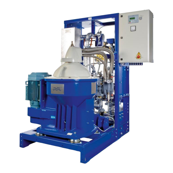
- Page 145 1.3 System Data 1 Technical Data 1.3.1 Module Weights including optional Sludge Removal Kit, kg Separator type (see Without Separator Module Type Steam Electric dimension drawings Heater in chapter 2) P 636 Single S 936 - S 937 Single S 946 - S 947 Single Separation Module Planned Maintenance Kits (not including wear items) Sludge Feed Control...
- Page 146 Mechanical Drawings...
- Page 150 MAN Managua: LO S946 Module, 4500968861-10 to -80, Mat Nr 11.63010-0244...
- Page 152 2.6 Change of EPC 60 Components 2 Mechanical Drawings Change of EPC 60 Components Operating Panel • Switch power off. • Remove the connections on the reverse side of the panel. • Unscrew the four screws holding the panel and remove the panel.
- Page 153 2 Mechanical Drawings 2.6 Change of EPC 60 Components • Pull away the cable terminal. • Hold down the triangle on the top of the I/O board and loosen the board. • Pull the board straight out (otherwise it can fasten in one of its guides) •...
- Page 154 2.6 Change of EPC 60 Components 2 Mechanical Drawings • Mount the new I/O board by pressing it straight into place. Make sure the board is firmly in place otherwise it will be impossible to mount the cable terminal. • Remount the cable terminal.
- Page 155 Electrical Drawings...
- Page 190 4 Specifications • Only qualified personnel are allowed to work with lifting of the module. • Use only the lifting lugs as shown in the illustrations. • Slings or wires used for lifting the Module must be adjusted so that the beam is located above the centre of gravity.
- Page 191 All cables are markes to simplify identification and fault finding. Specifications The following specifications apply to cables connected to and from Alfa Laval equipment. Follow the instructions given in the cable list.Examples of cable types that can be used. •...
- Page 192 4 Specifications 4.2 Cable Routing Cable Routing Recommendations Power cables carry the power supply to motors, heaters, etc. Any distance between signal and power cables reduces electrical noise transfer. Examples of recommended routing of various cable types. Power Power Power Power Power Signal...
- Page 193 4.3 Oil, Water, Steam, and Condensate Piping 4 Specifications 4.3 Oil, Water, Steam, and Condensate Piping For piping to and from Alfa Laval equipment, see the specifications below. Specifications • The correct pipe size must be used in the oil system. • The number of bends in the oil pipes must be minimized.
- Page 194 +55 °C. To meet this regulation, it is essential that electrical and electronic components have good ventilation, and temperature control. Heat Tracing and Insulation of Fuel Oil, Sludge, and Steam Pipes. Alfa Laval can, on request, supply modules which are heat traced and insulated, as optional equipment.
- Page 195 4.6 More than one Oil Tank 4 Specifications More than one Oil Tank Recommendation When one separator servres more than one oil tank, both the suction and the outlet lines should be Unprocessed Clean oil fitted with change-over valves. To avoid oil transfer from one tank to another, these valves must be Change- interlinked.
- Page 196 4 Specifications 4.7 Sludge Removal Kit (optional Equipment) Sludge Removal Kit (Optional Equipment) If you have a Sludge Removal Kit, this mut be connected to a ventilation pipe. The sludge removal pump must be set to the correct speed – circa 60 strokes/min, otherwise the lifetime of the diaphragm, valve balls, and air motor will be severely shortened.
- Page 197 4.7 Sludge Removal Kit (optional Equipment) 4 Specifications Impurities gather in the Sludge Removal Kit tank. Regularly check the tank and level switch. See instructions below Proceed as follows: • From the Control Panel, run the sludge pump manually for a few seconds. •...
- Page 198 In retrofit applications, where an Alfa Laval Separation Module will share a common separator sludge tank with existing separators, it is recommended to install a...
- Page 199 4.8 Sludge Tank 4 Specifications The number of ventilation pipes, and their minimum dimension, depend on the size and number of separators connected to the same tank. See table below. modules Type 1 module 2/3 modules 4 moudles ø ø ø...
- Page 200 4 Specifications 4.9 Sludge Piping Sludge Piping Specification • The sludge pipe from the separator to the sludge tank should be vertical. If a vertical pipe is not possible, the deviation (A) from the vertical line must not exceed 30°. •...
- Page 201 5.2 Lifting Single Module with Electric Heater 4 Specifications...
- Page 202 Single Module Lifting Instructions 5.1 Lifting Single Module with Steam/Hot Water/ Thermal Oil Heater. Weight = max. 790 kg Weight = max. 865 kg X = 525 Y = 580 Centre of gravity Z = 650 Secure the module to prevent tipping (A) X024663b Weight = max. 790 kg Weight = max.
- Page 203 Commissioning and Initial Start Completion Check List It is essential before starting up the separation system that all modules are in good operating condition and that all pipelines and control equipment are properly connected to assure correct operation. Use this check list as a guide for completing the system installation: Breakdown hazard Check that the power frequency is in agreement with...
- Page 204 6.2 Initial Start-up 6 Commissioning and Initilal Start Separators are delivered without oil in the oil sump. For information on oil filling and oil type, see the Separator Manual booklet. Too much, or too little oil may result in damage to separator bearings.
- Page 205 6 Commissioning and Initilal Start 6.2 Initial Start-up 4. Check all parameter settings in the control unit. See Installation Parameters in the Parameter List booklet. 5. Check the separator. Always lubricate the bearings before start-up. The Separation module is supplied with standard configuration parameters. You may have to make some changes to suit your installation. 6.
- Page 206 6.2 Initial Start-up 6 Commissioning and Initilal Start • Note the pressure in the oil outlet PT4, both on the pressure gauge and in the EPC 60 display. This pressure is P min. • Gradually close the back pressure regulating valve RV4.
- Page 207 6 Commissioning and Initilal Start 6.2 Initial Start-up 6.2.1 Calculating Operating Pressure • Calculate the normal back pressure level during operation as follows: normal • Calculate the value for low pressure alarm setting (Pr 11) as follows: normal = Plow press •...
- Page 208 6.2 Initial Start-up 6 Commissioning and Initilal Start...
- Page 209 Shut-down and Storage Storage before Installation If the separation module is stored before installation, the following safeguards must be taken: Storage period 1 < 6 months > 6 months See Action before storage Protect from dust, dirt, This chapter water, etc. Protect with anti-rust oil This chapter Action before...
- Page 210 7.2 Protection and Storage 7 Shut-down and storage Protection and Storage All system equipment, both the separator and the ancillary equipment, must be stored indoors at 5 – 55°C, if not delivered in water-resistant box for outdoor storage. If there is a risk for condensation of water, the equipment must be protected by ventilation and heating above dew point.
- Page 211 7 Shut-down and storage 7.2 Protection and Storage Separator Dismantle the separator bowl and take out the O-rings. Clean the bowl with oil and reassemble without the O-rings. Place in a plastic bag with silica dessicant bags and seal the plastic bag. Grease the spindle.
- Page 212 7.3 Reassembly and Start up 7 Shut-down and storage Reassembly and Start up • Clean away the anti-rust oil with white spirit. • Remove the silica gel bags from all modules. • Pre-lubricate the separator spindle bearings • If stored for 6 months or longer, perform an inspection service (including change of oil in the separator sump).
- Page 213 Separator Manual High Speed Separator S 946 Specification No. 881203-05-02/2 Book No. 9006919-02 rev. 3...
- Page 214 Telephone: +46 8 530 650 00 +46 8 530 310 40 Telefax: © Alfa Laval Tumba AB 08-2014 The original instructions are in English This publication or any part there of may not be reproduced or transmitted by any process or means without prior written permission of Alfa Laval Tumba AB.
- Page 215 Contents Read this first Safety instructions Warning signs in text Environmental issues Requirements of personnel Remote start Basic principles of separation Introduction Separation by gravity Centrifugal separation Separating temperatures Design and function Overview Drive section Process section Sensors and indicators Separating function 4.5.1 The liquid balance in the bowl...
- Page 216 Service, dismantling, assembly Periodic maintenance 6.1.1 Maintenance intervals 6.1.2 Maintenance procedure 6.1.3 Tightening of screws 6.1.4 Service kits 6.1.5 Cleaning Maintenance logs Dismantling 6.3.1 Introduction 6.3.2 Tools 6.3.3 Frame hood 6.3.4 Bowl 6.3.5 Driving device 6.3.6 Centrifugal clutch Actions before assembly 6.4.1 Cleaning 6.4.2...
- Page 217 7.1.8 Starting time too long Separating functions 7.2.1 Bowl opens accidentally during operation 7.2.2 Bowl fails to open for sludge discharge 7.2.3 Unsatisfactory separation result 7.2.4 Bowl fails to close Technical reference Product description 8.1.1 Directives and standards Technical data Connection list Interface description 8.4.1...
- Page 219 Study instruction manuals and observe the warnings before installation, operation, service and maintenance. Not following the instructions can result in serious accidents. In order to make the information clear only foreseeable conditions have been considered. No warnings are given, therefore, for situations arising from the unintended usage of the machine and its tools.
-
Page 221: Read This First
Alfa Laval separator If the separator has been delivered and installed by Alfa Laval as a part of a processing system, this manual should be viewed as part of the System Documentation. Study carefully all instructions in any System Documentation. - Page 222 1 Read this first Fault finding Refer to this chapter if the separator functions abnormally. If the separator has been installed as a part of a processing system, always refer to the trouble-tracing instructions, in the System Documentation. Technical reference This chapter contains technical data concerning the separator and drawings.
-
Page 223: Safety Instructions
Strictly follow the instructions for installation, operation and maintenance. • Ensure that personnel are competent and have sufficient knowledge of maintenance and operation, especially concerning emergency stopping procedures. • Use only Alfa Laval genuine spare parts and the special tools supplied. - Page 224 • Use the separator only for the purpose and m /h parameter range specified by Alfa Laval. kg/m r/min • Check that the gear/pulley ratio is correct for power frequency used. If incorrect,...
- Page 225 2 Safety instructions Electrical hazard • Follow local regulations for electrical installation and earthing (grounding). • To avoid accidental start, switch off and lock power supply before starting any dismantling work. Crush hazards • Use correct lifting tools and follow lifting instructions.
- Page 226 2 Safety instructions Flying objects • Risk for accidental release of snap rings and springs when dismantling and assembly. Wear safety goggles. Health hazards • Risk for unhealthy dust when handling friction blocks/pads. Use a dust mask to make sure not to inhale any dust...
-
Page 227: Warning Signs In Text
2 Safety instructions Warning signs in text Pay attention to the safety instructions in this manual. Below are definitions of the three grades of warning signs used in the text where there is a risk for injury to personnel. DANGER indicates an imminently hazardous situation which, if not avoided, will result in death or serious injury. -
Page 228: Environmental Issues
2 Safety instructions Environmental issues Unpacking Packing material consists of wood, plastics, cardboard boxes and in some cases metal straps. Wood and cardboard boxes can be reused, recycled or used for energy recovery. Plastics should be recycled or burnt at a licensed waste incineration plant. -
Page 229: Requirements Of Personnel
2 Safety instructions Requirements of personnel Only skilled or instructed persons are allowed to operate the machine, e.g. operating and maintenance staff. • Skilled person: A person with technical knowledge or sufficient experience to enable him or her to perceive risks and to avoid hazards which electricity/mechanics can create. - Page 230 2 Safety instructions...
-
Page 231: Basic Principles Of Separation
3 Basic principles of separation Introduction The purpose of separation can be: • to free a liquid of solid particles, • to separate two mutually insoluble liquids with different densities while removing any solids presents at the same time, • to separate and concentrate solid particles from a liquid. -
Page 232: Centrifugal Separation
3 Basic principles of separation Centrifugal separation In a rapidly rotating bowl, the force of gravity is replaced by centrifugal force, which can be thousands of times greater. Separation and sedimentation is continuous and happens very quickly. The centrifugal force in the separator bowl can achieve in a few seconds what takes many hours in a tank under influence of gravity. -
Page 233: Design And Function
4 Design and function G08707A1 Process section The feed inlet and outlets are situated at the top of the separator. The liquid is cleaned in the rotating separator bowl inside the frame hood. Sensors The separator is monitored by a speed sensor. An unbalance sensor and an interlocking switch are optional. -
Page 234: Overview
4 Design and function Overview The separator comprises a process section and a drive section powered by an electric motor. The separator frame comprises a lower body and a frame hood. The motor is attached to the frame. The frame feet dampen vibration. The bottom part of the separator contains a flat belt transmission, a centrifugal clutch and a vertical spindle. -
Page 235: Drive Section
4 Design and function Drive section The separator bowl is driven by an electric motor via a belt transmission. The belt pulley on the motor shaft includes a centrifugal clutch. The centrifugal clutch (2) with friction pads ensures a gentle start and smooth acceleration, and at the same time prevents overloading of the belt and motor. -
Page 236: Process Section
4 Design and function Process section The separation process takes place inside the rotating separator bowl. The feed and outlet of process liquid takes place in the in and outlet unit on top of the separator frame hood. Inlet and outlet The inlet and outlet unit consists of the following parts: A connection house for pipe connections. - Page 237 4 Design and function Separator bowl The separator bowl, with its sludge discharge mechanism, is built-up as follows: The bowl body and bowl hood are held together by a lock ring (Centrilock). Inside the bowl are the distributor and the disc stack. The disc stack is kept compressed by the bowl hood.
-
Page 238: Sensors And Indicators
4 Design and function Sensors and indicators The separator is equipped with a speed sensor. As options, an unbalance sensor and an interlocking kit can be fitted. Speed sensor (optional) A speed sensor (3) indicates the speed of the separator. The correct speed is needed to achieve the best separating results and for reasons of safety. -
Page 239: Separating Function
4 Design and function Separating function The separator separates water and solids from the uncleaned oil. Water normally leaves the separator through the water outlet. During sludge discharge, solids (sludge) and water are removed through the discharge ports. 4.5.1 The liquid balance in the bowl The liquid levels in the bowl depend on many factors (bowl geometry, liquid densities, flow... -
Page 240: Liquid Flow
4 Design and function 4.5.2 Liquid flow Unseparated oil is fed into the bowl through the inlet pipe and travels via the distributor towards the periphery of the bowl. When the oil reaches slots in the distributor, it rises through the channels formed by the disc stack, where it is evenly distributed. -
Page 241: Discharge Of Sludge And Water (Alcap™ Concept)
4 Design and function 4.5.3 Discharge of sludge and water (ALCAP™ concept) As the sludge space fills up and water enters the disc stack, traces of water will escape with the cleaned oil. The increase of water content in the cleaned oil is the sign of reduced separation efficiency. -
Page 242: Discharge Of Water Through Water Outlet
4 Design and function 4.5.4 Discharge of water through water outlet G08862b1 Discharge of water through water outlet A. Unseparated oil B. Separated oil C. Water 1. Water paring tube 2. Water paring chamber 3. Holes in distributor 4. Top disc 5. -
Page 243: Operating Instructions
5 Operating instructions These operating instructions describe routine procedures to follow before and during the start, running and stopping sequences of the separator. If system documentation is available, always follow the operating instructions therein. If there is no system documentation, the instructions below are to be followed. -
Page 244: Start After Service
5 Operating instructions • Remove the oil pin and make sure that the oil level is above the lower end of the pin, Oil change on page 160. Too much or too little oil can damage the separator bearings. The separator should be level and at standstill when oil is filled. -
Page 245: Normal Operation
5 Operating instructions Normal operation 5.2.1 Before normal start To achieve the best separation results, the bowl should be in a clean condition. Check: that all couplings and connections (1) are securely tightened to prevent leakages. Leaking hot liquid can cause burns. -
Page 246: Start
5 Operating instructions 5.2.2 Start Start of separator: a. Open the water supply valve. b. Start the separator by pushing the start button at the starter unit. After every start the separator must always be run continuously for a minimum of 5 hour to ensure proper lubrication. - Page 247 5 Operating instructions Ensure that the separator is at full speed. The time by full speed can be checked by studying the ammeter. Current increases during start (1). When full speed has been reached, the current decreases to a stable value (2).
-
Page 248: Operating
5 Operating instructions 5.2.3 Operating Checkpoints during operation. Burning hazard Lubricating oil and various machine surfaces can be hot and cause burns. a. Check all connections for leakage. b. Check that the feed has correct flow and temperature. c. Check the back pressure. d. - Page 249 5 Operating instructions 5.2.3.1 Sludge discharge Turn off the oil feed. Perform a displacement of the oil by adding hot water (not more than bowl volume). Perform a sludge discharge. a. Add opening water until a discharge sound is heard (max. 3 seconds). b.
-
Page 250: Stop
5 Operating instructions 5.2.4 Stop Stopping the separator. Turn off the oil feed. Perform a displacement of the oil by adding hot water (not more than bowl volume). Perform a sludge discharge. a. Add opening water until a discharge sound is heard (max. 3 seconds). b. -
Page 251: Emergency Stop
G0871381 Disintegration hazard After an emergency stop, the cause of the fault must be identified. If all parts have been checked and the cause not found, contact Alfa Laval for advice before restarting the separator. - Page 252 5 Operating instructions...
- Page 253 6 Service, dismantling, assembly Periodic maintenance Periodic (preventive) maintenance reduces the risk of unexpected stoppages and breakdowns. Follow the maintenance log in this chapter in order to facilitate the periodic maintenance. 6.1.1 Maintenance intervals The following directions for periodic maintenance give a brief description of parts to be cleaned, checked and renewed at different maintenance intervals.
- Page 254 6 Service, dismantling, assembly Electric motor Motor service consists of an overhaul of the motor at max. 36 months or 24000 operating hours. Bearings, fan, seals and washers for the motor are renewed. Ancillary Verify correct flow at inspection service overhaul water valveblock at least every 36 months.
- Page 255 6 Service, dismantling, assembly 6.1.2 Maintenance procedure At each Inspection and/or Overhaul, take a copy of the maintenance log and use it to make notes during the service. An inspection and overhaul should be carried out as follows: Dismantle the parts as described in Dismantling on page Place the separator parts on clean, soft surfaces such as pallets.
- Page 256 6 Service, dismantling, assembly The use of service symbols in the dismantling/assembly instructions Parts that have to be renewed from the service kits (see below) are marked [i] and/or [o] in the assembly instructions. Example a. Fit the O-ring [i]. When dismantling and assembling between the service periods, some procedures do not have to be carried out.
- Page 257 Overhaul kit. The contents of the kits are described in the Spare Parts Catalogue. Always use Alfa Laval genuine parts as otherwise the warranty may become invalid. Alfa Laval takes no responsibility for the safe operation of the equipment if non-genuine spare parts are used.
- Page 258 6 Service, dismantling, assembly Maintenance logs Name of ship/plant: Local identification: Separator: Manufacture No./Year: Total running hours. Product No: Signature: Date: Part [i] [o] Check Action Page Note In and outlet device - All parts Clean - All parts Check for corrosion - All parts Check for cracks - Connecting housing...
- Page 259 6 Service, dismantling, assembly Part [i] [o] Check Action Page Note - Lock ring Check for deformations Check for impact marks Check pin not deformed or loose - Bowl hood Renew seal ring Renew O-ring Renew seal ring and screws - Operating water ring Frame Has to be...
- Page 260 6 Service, dismantling, assembly Part [i] [o] Check Action Page Note - Coupling hub Renew single row ball bearings Renew snap rings - Friction block Renew friction pads (if they are worn) or clean the pads if they are dirty Electrical motor - Bearings Renew bearings, fan, seals...
- Page 261 6 Service, dismantling, assembly Dismantling 6.3.1 Introduction The frame hood and heavy bowl parts must be lifted by means of a hoist. Position the hoist exactly above the bowl centre. Use a lifting sling and lifting hooks with safety catches. The parts must be handled carefully.
- Page 262 6 Service, dismantling, assembly Standard Tools G0911691 Screwdriver Torque wrench (capacity 0-200 Nm) Drift (Ø 4 mm) Dial indicator with magnetic base Hexagon head keys, various sizes Heating equipment for bearings Sliding calliper Hammers (standard and soft-faced) Pliers for internal snap rings 10.
- Page 263 6 Service, dismantling, assembly 6.3.3 Frame hood G0863331 G1019211 1. Hook spanner (for the lock nut) G08634M1 1. Lock nut 2. Washer 3. Connecting housing 4. Spring 5. Screw 6. Arm 7. Screws 8. Frame hood 9. O-ring 10. Height adjusting rings 11.
- Page 264 6 Service, dismantling, assembly Removing the connecting housing. a. Remove connections before starting dismantling. b. Lubricate the inlet pipe thread c. Remove the lock nut, using the hook spanner, and the washer. The nut must not be removed before the separator has stopped.
- Page 265 6 Service, dismantling, assembly Removing the spring and arm. G08636m1 A. Spring B. Screw C. Lock washer D. Arm a. Remove the spring (A) from the pin on the hood. b. Remove the screw (B) and lock washer (C) from the arm. c.
- Page 266 6 Service, dismantling, assembly Removing the frame hood. a. Remove the screws (A) holding the frame hood. b. Loosen the hood by bending with a screwdriver (B) in all grooves in the hood. c. Lift off the frame hood. Do not place the hood upside down. G08636I1 A.
- Page 267 6 Service, dismantling, assembly 6.3.4 Bowl G0861621 G1019221 1. Compressing tool (lock ring) 2. Lifting eyes 3. Spanner for nut (nut/discharge slide) 4. Puller (discharge slide) 5. Lifting tool (distributor, spindle) 6. Puller (Bowl body) 7. Screw (lock ring) (M5) 8.
- Page 268 6 Service, dismantling, assembly G1029061...
- Page 269 6 Service, dismantling, assembly 1. Lock ring 2. Bowl hood 3. Seal ring 4. O-ring 5. Top disc 6. O-rings 7. Inlet and outlet pipe 8. Paring tube 9. Splash sealing 10. Bowl disc (without caulks) 11. Bowl discs 12. Distributor 13.
- Page 270 6 Service, dismantling, assembly Removing the lock ring. a. Fit the compressing tool (A). b. Fit the clamps (C) and the screws (B) to stop. Be sure not to cover the threaded holes for the lock ring. c. Compress the disc stack by alternately tightening the inner screws (F) on the compressing tool in increments of 5 Nm up to a maximum of 30 Nm.
- Page 271 6 Service, dismantling, assembly Removing the bowl hood. a. Remove the compressing screws (A). b. Loosen the screws (B) on the clamp tool. Remove the tool. Remove the lock ring. See removing the bowl hood with optional hydraulic tool (if purchased) on next page. c.
- Page 272 6 Service, dismantling, assembly Removing the bowl hood using the hydraulic tool (optional). First remove the lock ring according to instructions a -b, on previous page. a. Fit the larger stud bolt (A) into the in- and outlet pipe (must rest on the cap nut).
- Page 273 6 Service, dismantling, assembly Removing the seal ring. a. Place the bowl hood on a support and tap out a piece of the seal ring (A) using a drift in the holes. Risk for eye injury from flying seal ring parts or from splashing fluid The seal ring breaks when removed from the bowl hood and may cause trapped fluid to splash.
- Page 274 6 Service, dismantling, assembly Removing the paring tube. a. Remove the top disc (A) from the inlet and outlet pipe. To avoid damaging the paring tube, turn it towards the centre of the pipe. b. Remove the splash sealing (B). c.
- Page 275 6 Service, dismantling, assembly Removing the disc stack and distributor. G08631C1 A. Lifting tool B. Disc stack C. Bowl discs D. Pin a. Assemble the lifting tool (A) with the pin (D). b. Fit the assembled tool into the distributor and ease off the disc stack using a spanner or wrench.
- Page 276 6 Service, dismantling, assembly Removing the nut. Before the nut can be loosened, the bowl body must first be secured to prevent it from rotating. a. Fit a lifting sling on one of the compressing tool clamps (A). Fit the clamp (A) to the bowl body.
- Page 277 6 Service, dismantling, assembly Removing the discharge slide. a. Fit the lifting tool (A) by pressing the puller rods (E) towards each other and position them into the two slots on the bowl body (F). Slide metal ring (D) down over bowl nave.
- Page 278 6 Service, dismantling, assembly 10. Removing the cap nut. a. Remove the cap nut (A). Left-hand thread! G08606F1 A. Cap nut 11. Removing the bowl body. G0860741 A. Lifting tool B. Lifting eye a. Fit the lifting tool (A) to the bowl body. b.
- Page 279 6 Service, dismantling, assembly 12. Turn the bowl body upside down. G0860841 Crush hazard Support the bowl body when turning to prevent it from rolling.
- Page 280 6 Service, dismantling, assembly 13. Removing the holder. G0860951 A. Screw B. Holder C. Threaded hole D. Washer a. Remove and discard the screws (A) and washers (D). New screws and washers are included in the Inspection kit. b. Remove the holder (B). If the ring sticks, use two M8 screws in threaded holes (C) to raise the operating slide holder up and away from the bowl body.
- Page 281 6 Service, dismantling, assembly 14. Removing the operating slide. a. Lift off the operating slide. If the ring sticks, use two M8 screws in threaded holes to raise the operating slide holder up and away from the bowl body. G08610N1 A.
- Page 282 6 Service, dismantling, assembly 16. Removing the guide ring. [O] a. Gently pry loose the guide ring and remove it from the bowl. Discard the guide ring. A new guide ring is included in the Overhaul kit. Do NOT remove the guide ring if only an Inspection service is performed.
- Page 283 6 Service, dismantling, assembly 17. Removing the operating water ring. G0861141 A. Screw B. Ring C. Threaded hole a. Remove and discard the screws (A). New screws are included in the Inspection kit. b. Lift off the ring (B). If the ring sticks, use two M8 screws in threaded holes (C) to raise the operating slide holder up and away from the bowl body.
- Page 284 6 Service, dismantling, assembly 6.3.5 Driving device G0857821 G08579G1 1. Puller (spindle pulley, ball bearing) 2. Tool (bearing housing) 3. Cover puller (neck bearing cover) 4. Lifting tool (spindle assembly) 5. Drift (bottom bearing) 6. Sleeve (ball bearing in top bearing seat) 7.
- Page 285 6 Service, dismantling, assembly...
- Page 286 6 Service, dismantling, assembly G08580h1...
- Page 287 6 Service, dismantling, assembly 1. Seal ring 2. Operating water cover 3. O-ring 4. O-rings 5. O-ring 6. Pipe 7. Elbow 8. Bushing 9. Deflector ring 10. Seal rings 11. Neck bearing cover 12. O-ring 13. O-rings 14. Fan 15. Snap ring 16.
- Page 288 6 Service, dismantling, assembly Empty the oil sump. Unscrew the oil plug (A) and empty the oil sump. G08685A1 A. Oil plug Removing the belt cover. a. Remove the screws (1). b. Remove the belt cover (2). G0858191 1. Screw 2.
- Page 289 6 Service, dismantling, assembly Loosen the flat belt, by tilting the motor. a. Loosen, but do not remove, the screws holding the motor. Start with the two screws (4) at the bottom. b. Remove the two upper screws so that the motor can be tilted.
- Page 290 6 Service, dismantling, assembly Removing the operating water cover. G0858951 A. Screw B. Operating water cover C. Threaded holes a. Remove the screws (A). b. Lift off the operating water cover (B). If the cover (B) sticks, fit two M10 screws to the threaded holes (C) and tighten.
- Page 291 6 Service, dismantling, assembly Removing the neck bearing cover and deflector ring. G0859081 A. Tool B. Mounting screw C. Screw D. Cover E. Frame a. Attach the tools (A). b. Fasten the tool to the cover using mounting screw (B). c.
- Page 292 6 Service, dismantling, assembly Prepare for removal of spindle assembly. a. To facilitate later removal of the plugs, loosen (but do not remove) the plugs (A) on the bearing housing. b. Remove the screws (B) If the housing sticks, fit two M10 screws to the threaded holes and tighten.
- Page 293 6 Service, dismantling, assembly Lifting the spindle assembly from the frame. a. Fit the lifting tool (1) to the spindle end. b. Slowly raise and lift out the spindle assembly using a hoist. Crush hazard Do not rotate the spindle assembly during lifting.
- Page 294 6 Service, dismantling, assembly Place the spindle assembly upside down on a support. Make a support (1) with a free space (A) between the spindle top and the floor. G08592c1 A=5 mm Always use a support as per this sketch when overhaul service is performed on the spindle assembly.
- Page 295 6 Service, dismantling, assembly Removing the air deflector. a. Remove the screws (2) and the air deflector (1). G08592b1 1. Air deflector 2. Screw...
- Page 296 6 Service, dismantling, assembly 10. Removing the fan. a. Turn the spindle assembly the right way b. Place a spanner (or similar) on the spindle pulley key-grip (1), as holder-up. c. Fit the pin spanner and remove the fan (2). Left-hand thread! G0923981 1.
- Page 297 6 Service, dismantling, assembly 11. Removing the oil mist generator. a. Turn the spindle assembly up-side down and remove the oil mist generator (1) by using spanners. b. Remove the two nozzles (2) using an Allen key. G1036811 1. Oil mist generator 2.
- Page 298 6 Service, dismantling, assembly 13. Removing the top bearing housing. a. Turn the spindle assembly over. G0858251 1. Composite spring 2. Plug 3. Spindle 4. Axial springs b. Remove the snap ring (5). Risk for eye injury from flying snap ring Use the correct pliers for dismantling of snap ring to avoid accidental release.
- Page 299 6 Service, dismantling, assembly 14. Removing the ball bearing. a. Fit the cap nut (1) on the spindle to protect the threads. b. Use the puller tool (2) to remove the top bearing seat from the spindle. Take care not to damage the vibration indicator (3) when separating the top bearing seat from the spindle.
- Page 300 6 Service, dismantling, assembly 15. Removing the labyrinth ring holder. a. Remove the screws (1). If the holder sticks, fit two screws M8 to the threaded holes and tighten. b. Remove the O-ring and labyrinth ring. G08586G1 1. Screw...
- Page 301 6 Service, dismantling, assembly 16. Removing the bottom bearing holder. a. Fit the tool (4) into the bottom bearing holder and attach the socket (3), extension rod (2) and T-handle (1). G08586J1 1. T-handle 2. Extension rod 3. Socket 4. Tool b.
- Page 302 6 Service, dismantling, assembly 17. Dismantling the bottom bearing holder (when necessary). a. Unscrew the screw (3). b. Remove the pipe (1), O-rings (2), (4) and strainer (5). G1015731 1. Pipe 2. O-ring 3. Screw 4. O-ring 5. Strainer 6. Bottom bearing holder...
- Page 303 6 Service, dismantling, assembly 6.3.6 Centrifugal clutch G0864711 Entrapment hazard To avoid accidental start, switch off and lock-out power supply before starting any dismantling work. Make sure that machine has come to a complete standstill before starting any dismantling work (takes about 30 minutes from switch off).
- Page 304 6 Service, dismantling, assembly If belt cover and drive belt not has been removed proceed with this before removing the motor. See page Removing the motor. a. Disconnect the electrical cables. Electrical hazard To avoid electrical shock, switch off and lock power supply before starting dismantling work.
- Page 305 6 Service, dismantling, assembly Removing the friction blocks. a. Remove the snap ring (3), cover (2) and friction blocks (1). Flying objects Risk for accidental release of snap ring. Wear safety goggles. G08652g1 1. Friction blocks (3=60 Hz) 2. Cover 3.
- Page 306 6 Service, dismantling, assembly Checking the condition of the friction blocks. [o] Inhalation hazard When handling friction blocks/pads wear a mask to avoid inhalation of dust. Do not use compressed air to remove dust. Remove dust using vacuum or a damp cloth. If the blocks are worn: Fit new friction blocks.
- Page 307 6 Service, dismantling, assembly Removing the coupling from the motor (complete dismantling of centrifugal clutch). a. Attach a socket with extension rod and handle (1) to the screw. Place a piece of wood (2) according to the illustration. Push the handle to start the rotor moving, when the handle hits the piece of wood, the weight and movement of the rotor loosens the screw.
- Page 308 6 Service, dismantling, assembly Removing the coupling from the motor using the optional hydraulic tool. First remove the screw, spring washer and washer according to instructions a -b, on previous page. G08654Q1 1. Sleeve 2. Nut 3. Hydraulic cylinder 4. Hydraulic oil inlet 5.
- Page 309 6 Service, dismantling, assembly Attach the hose from the hand pump to the hydraulic oil inlet (4). Ease off the friction coupling by pumping the handle on the pump until stop. Release pressure on the hand pump and adjust the nut on the stud bolt. Repeat until coupling is loose.
- Page 310 6 Service, dismantling, assembly Dismantling of the coupling assembly. a. Remove the snap rings (1). Flying objects Risk for accidental release of snap ring. Wear safety goggles. b. Drive out the coupling hub (3). c. Turn the coupling the other way round and drive out the ball bearings (5) using the mounting tool.
- Page 311 6 Service, dismantling, assembly Actions before assembly 6.4.1 Cleaning [i], [o] Clean the separator parts according to the diagram below. Afterwards, protect all cleaned carbon steel parts against corrosion by oiling. Electrical hazard Never wash down a separator with a direct water stream.
- Page 312 — Remove the bowl discs from the Use Alfa Laval bowl disc cleaning agent. Mix 1 part distributor and place them individually in the cleaning agent. cleaning agent to 10 parts water.
- Page 313 Evidence of corrosion attacks should be looked for and rectified each time the separator is dismantled. Disintegration hazards Always contact your Alfa Laval representative if you suspect that the depth of the corrosion damage G0205241 exceeds 0,2 mm for bowl body and bowl hood (0,5 for other parts) or if cracks have been found.
- Page 314 Disintegration hazards Always contact your Alfa Laval representative if you suspect that the depth of the damage exceeds 0,2 mm for bowl body and bowl hood (0,5 for other parts).
- Page 315 Dents and pits having a granular and shiny surface. Inspect the bowl and inlet/outlet parts for erosion damages. Always contact your Alfa Laval representative if you suspect that the depth of the damage exceeds 0,2 mm for bowl body and bowl hood (0,5 for other parts).
- Page 316 6 Service, dismantling, assembly Surfaces particularly subjected to erosion are: G1033631 The sealing edge of the discharge slide. Bowl body and holder. Holder and operating slide. The underside of the distributor in the vicinity of the distribution holes and wings. Paring disc and paring tube.
- Page 317 6 Service, dismantling, assembly 6.4.5 Exchange of frame feet The frame feet have to be changed occasionally due to rubber deterioration from age. When replacing the frame feet, the separator must be lifted. Follow the instructions in Lifting instructions on page 170.
- Page 318 6 Service, dismantling, assembly 6.4.6 Lubrication of bowl parts Apply a thin layer of Molykote, or equivalent lubrication, on all the contact surfaces shown in the illustration. G09117j1 A. Molykote 1000 1. Bowl hood 2. Bowl body 3. Discharge slide 4.
- Page 319 6 Service, dismantling, assembly Assembly Entrapment hazard To avoid accidental start, switch off and lock power supply before starting assembly work.
- Page 320 6 Service, dismantling, assembly 6.5.1 Centrifugal clutch Assembly of the coupling. a. Slip the belt pulley (1) over the coupling hub and place them on a firm and level foundation. Disintegration hazard If the belt pulley must be renewed, check that the new pulley has the correct diameter.
- Page 321 6 Service, dismantling, assembly Fitting the coupling to the motor. Make sure that the key (1) is in place on the motor shaft. See mounting with optional hydraulic puller tool (if purchased) on next page. a. Clean the motor shaft and apply a thin oil film.
- Page 322 6 Service, dismantling, assembly Fitting the coupling to the motor with optional hydraulic tool. Make sure that the key (1) is in place on the motor shaft. a. Clean the motor shaft and apply a thin oil film. b. Fit the sleeve (7) to the stud bolt. Fit the stud bolt (2) with sleeve to the motor shaft (6).
- Page 323 6 Service, dismantling, assembly Fitting the friction blocks. a. Fit the friction blocks (2) onto the guide pins (1). Be sure that the pins on the back of the blocks project into the grooves in the clutch hub. 50 Hz = 5 Friction blocks 60 Hz = 3 Friction blocks b.
- Page 324 6 Service, dismantling, assembly Fitting the motor. a. Fit a lifting sling to the motor. Use a shackle from the separator lifting tool. Weight of motor with coupling: approx. 84 kg. b. Lower the motor (while supported) on to the separator frame. It will set on the ledge.
- Page 325 6 Service, dismantling, assembly Fitting the flat belt. Clean the inside of the frame before fitting the flat belt, and make sure that there is no oil on the belt. a. Lift up the belt (1) to the middle (centre) of the spindle pulley.
- Page 326 6 Service, dismantling, assembly Fitting the belt cover. a. Fit the belt cover. b. Tighten the screws. G08581A1 1. Screw 2. Belt cover...
- Page 327 6 Service, dismantling, assembly 6.5.2 Driving device Assembling the bottom bearing holder (where necessary) Clean the pipe and strainer before fitting. Make sure to fit the pipe the right way up! a. Fit the pipe (1), O-rings (2,4) and strainer (5). b.
- Page 328 6 Service, dismantling, assembly Fitting the bottom bearing holder. a. To secure the bottom bearing holder (3) into the frame, apply Loctite 222 on the surfaces directly above the upper O-ring. b. Thread the bottom bearing holder (3) into the frame and fit the tool into the bottom bearing housing.
- Page 329 6 Service, dismantling, assembly Fitting the labyrinth ring holder. G0866381 1. O-ring 2. Labyrinth-ring a. Lubricate and fit the O-ring (1). [o] b. Lubricate and fit the labyrinth ring (2). c. Fit the labyrinth ring holder into the frame. Apply Loctite 222 to screws (3). Fit and tighten the screws.
- Page 330 6 Service, dismantling, assembly Fitting the ball bearing to the top bearing seat. [o] a. Heat the top bearing seat (1) in oil to minimum 110 °C and maximum 125 °C, either using hot clean oil or induction heater (induction heater is recommended).
- Page 331 6 Service, dismantling, assembly Fitting the top bearing seat with bearing to the spindle. a. Heat the top bearing seat (1) and bearing to minimum 110 °C and maximum 125 °C, either using hot clean oil or induction heater. Burn hazard Use protective gloves when handling any heated parts.
- Page 332 6 Service, dismantling, assembly Fitting the top bearing housing. a. Fit the axial springs (2) to the top bearing housing. [o] b. Carefully lower the bowl spindle (1). Make sure that the springs enter the recesses on the top bearing seat. c.
- Page 333 6 Service, dismantling, assembly Fitting the spindle pulley. a. Screw on the cap nut on the spindle. b. Turn the spindle assembly upside down and let the spindle rest on the cap nut. It is of utmost importance to use cap nut and the support as the neck bearing may be forced out of its position and damage the neck bearing when the bottom bearing is...
- Page 334 6 Service, dismantling, assembly Fitting the self-aligning roller bearing. [o] a. Lubricate the bearing with clean oil. b. Heat the bearing (1) to minimum 30 °C and maximum 50 °C. Burn hazard Use protective gloves when handling any heated parts. c.
- Page 335 6 Service, dismantling, assembly Fitting the oil mist generator. G08669f1 1. Nozzle 2. Oil mist generator 3. Threads Clean the oil mist generator and nozzles before assembly. a. Apply Loctite 222 and screw the two nozzles (1) into the pump (2) so that they lie level with the pump edge using an Allen key.
- Page 336 6 Service, dismantling, assembly 10. Fitting the fan. a. Turn the spindle assembly to up-right position. Ensure that the spindle is seated against the inner ring of the ball bearing. b. Apply a thin layer of oil and fit the O-rings (1) into the fan.
- Page 337 6 Service, dismantling, assembly 11. Fitting the air deflector. a. Turn the spindle assembly up-side down and fit the air deflector (1). b. Tighten screws (2). G08592A1 1. Air deflector 2. Screw...
- Page 338 6 Service, dismantling, assembly 12. Lowering the spindle assembly into the frame. a. Turn the assembly and remove the cap nut from the spindle. Fit the lifting tool (1) to the spindle assembly and lift it. Crush hazard Do not rotate the spindle assembly during lifting.
- Page 339 6 Service, dismantling, assembly 13. Fitting the flat belt. Clean the inside of the frame before fitting the flat belt, and make sure that the belt is clean. a. Lift up the belt (1) to the middle (centre) of the spindle pulley. For correct position, centre the belt on the spindle pulley camber.
- Page 340 6 Service, dismantling, assembly 14. Fitting the neck bearing cover and deflector ring. G08680T1 1. Seal ring 2. O-rings 3. Neck bearing cover 4. Deflector ring a. Apply a thin layer of oil and fit the O-rings (2) and seal rings (1). [o] b.
- Page 341 6 Service, dismantling, assembly 15. Fitting the operating water cover. a. Check that the operating water channel (5) is not clogged. Clean if necessary. A blocked operating water channel can lead to failure of the separator discharge function. b. Lubricate with oil and fit the seal ring (1) and O-ring (3) into the operating water cover (2).
- Page 342 Fit a dial indicator in a support and fasten it in position as illustrated. Use the flat belt to turn the spindle. Permissible radial wobble: max. 0,04 mm. If the spindle wobble exceeds this value, contact an Alfa Laval representative.
- Page 343 6 Service, dismantling, assembly 17. Fitting the belt cover. a. Fit the belt cover (2). b. Tighten the screws (1). G08581A1 1. Screw 2. Belt cover...
- Page 344 6 Service, dismantling, assembly 18. Fill oil in the oil sump. The separator should be level and at standstill when oil is filled. a. Remove the oil pin (1), plug (3) and washer (4). b. Fit new washer (6) and refit the drain plug (5).
- Page 345 6 Service, dismantling, assembly 6.5.3 Bowl Check for impact marks and corrosion in bowl body nave and on spindle taper.[i], [o] a. Remove any impact marks using a scraper and/or a whetstone. Disintegration hazard Impact marks may cause the separator to vibrate while running.
- Page 346 6 Service, dismantling, assembly Fitting new valve plugs on the operating slide. [i] a. Carefully tap in new valve plugs, using a clean, soft-faced hammer. Make sure that the plugs are fitted as described in the illustration. G0874871...
- Page 347 6 Service, dismantling, assembly Fitting the guide ring. [o] a. Pointwise apply a small amount of silicone grease in the groove on bowl body (2) and mount the guide ring (1) into the groove on bowl body. Secure that the guide ring is fully inserted into the groove and that it is secured in its position by the silicone grease.
- Page 348 6 Service, dismantling, assembly Fitting the operating slide. a. Apply a thin layer of silicone grease and fit the rectangular ring (6) on the operating slide and the rectangular ring (8) and O-ring (7) on the bowl body (3). [i],[o] b.
- Page 349 6 Service, dismantling, assembly Fitting the operating slide holder. a. Fit the holder (1) over the operating slide. b. Apply a thin layer of molykote grease and fit and tighten new screws (2) and washers (3) to a torque of 30 ± 2 Nm. [i], [o] It is very important NOT to refit used screws and washers.
- Page 350 6 Service, dismantling, assembly Fitting the operating water ring. a. Assemble the seal ring (5) into the operating water ring (2). [i], [o] It is very important not to refit used screws. Always fit new ones included in the Inspection kit! b.
- Page 351 6 Service, dismantling, assembly Lifting the bowl body onto the spindle taper. a. Put a drop of oil on the spindle taper (1). b. Wipe off the spindle taper (1) and nave bore (2) with a dry cloth. c. Turn the bowl body over. Crush hazard Support the bowl body when turning to prevent it from rolling.
- Page 352 6 Service, dismantling, assembly Fitting and tightening the cap nut. a. To prevent the bowl body from rotating when fitting the cap nut; Fit one of the clamps (2) to the bowl body and one of the screws (4) for the frame hood in the frame.
- Page 353 6 Service, dismantling, assembly Fitting the discharge slide. a. Apply a thin layer of silicone grease and fit the rectangular ring (1). [i], [o] b. Apply a thin layer of silicone grease and fit the O-ring (3). [i], [o] c. Fit the lifting tool (2) and lower the discharge slide into the bowl.
- Page 354 6 Service, dismantling, assembly 10. Assembly of the disc stack. a. Fit the discs (1) one by one onto the distributor. The distributor has a guide rib (4) for the correct positioning of the bowl discs. Always end with the disc without caulks.
- Page 355 6 Service, dismantling, assembly 11. Fitting the disc stack assembly to the bowl body. a. Fit the lifting tool (1) into the distributor. b. Lower the disc stack into the bowl using sling and hoist. The guide pin (2) on the bowl body should face the drill mark (3) on the distributor.
- Page 356 6 Service, dismantling, assembly 12. Assembling the paring tube. [i] a. Apply a thin layer of silicone grease to the O-rings (1). Fit the O-rings (1) and bearings (2) to the paring tube. [i], [o] G09849G1 1. O-ring 2. Bearing...
- Page 357 6 Service, dismantling, assembly 13. Mounting the paring tube and fitting the inlet and outlet pipe. a. Insert the paring tube (1) to the inlet and outlet pipe. b. Apply a thin layer of silicone grease and mount the splash sealing (2). [i], [o] c.
- Page 358 6 Service, dismantling, assembly 14. Fitting the top disc. a. Move the paring tube (1) to the centre. To avoid damaging the paring tube, turn it towards the centre of the pipe. b. Lower the top disc (2). The drill mark (3) on the top disc should face the guide pin on the bowl body.
- Page 359 6 Service, dismantling, assembly 15. Fitting the bowl hood. a. Apply a thin layer of silicone grease and fit the O-ring (1). [i], [o] b. Fit the seal ring (2). Press the ring down evenly into the groove all around. [i], [o] c.
- Page 360 6 Service, dismantling, assembly 16. Fitting the lock ring. a. Place the lock ring (1) on the bowl hood (4) with its guide pin (5) close to the corresponding hole (6) in the bowl body (2). Make sure that the groove in the bowl body which retains the lock ring is clean.
- Page 361 6 Service, dismantling, assembly d. Measure gap C of lock ring and make sure it does not exceed 3 mm. If the lock ring gap is greater than 3 mm, the lock ring is damaged and must be replaced with a new one immediately. Health hazard Welding of the lock ring is not allowed, as this can seriously affect the material strength.
- Page 362 6 Service, dismantling, assembly 17. Checking the disc stack pressure. [i] a. Remove bowl hood, top disc and inlet and outlet pipe. b. Add one disc (1) to the disc stack. c. Refit the disc without caulks (2), the top disc and bowl hood.
- Page 363 6 Service, dismantling, assembly 6.5.4 In and outlet device Fitting the frame hood. [i], [o] a. Turn the paring tube (1) so that the frame hood (2) can pass the paring tube. b. Apply a thin layer of silicone grease and fit the O-ring (3) onto the frame hood.
- Page 364 6 Service, dismantling, assembly Control measurement of paring disc height. a. Remove the guide screw (A). b. Measure the distance D through the screw hole. Assemble the correct number of height adjusting rings (B) according to the list. 29 ± 0,5 mm, 3 rings 28 ±...
- Page 365 6 Service, dismantling, assembly Fitting the spring and arm. [o] a. Fit the spring (2) on the arm (3) and fit the arm to the top of the paring tube end (4) with the screw (1). b. Fit the spring to the pin (5) on the frame hood and make sure that it is properly attached on both ends.
- Page 366 6 Service, dismantling, assembly Fitting the connecting housing. a. Lubricate the inlet pipe thread. b. Fit the connecting housing (1) over the inlet/outlet pipe. Make sure that the screw, on top of the frame hood, enters the guide hole at the underside of the connecting housing.
- Page 367 6 Service, dismantling, assembly 6.5.5 Unbalance sensor (optional) Fitting the unbalance sensor holder. a. Remove the cover (1). b. Fit the O-ring (3) on the holder (2). Fit the screw (4) into the holder and mount the holder into the separator frame (6).
- Page 368 6 Service, dismantling, assembly Adjusting the unbalance sensor a. Fit the sensor (1) into the holder. Do not forget the nut (2). b. Adjust the sensor so that a value of 1,5 appears on the display. c. When correct distance is achieved tighten the nut against the holder.
- Page 369 6 Service, dismantling, assembly 6.5.6 Speed sensor (optional) Adjusting the speed sensor. a. Adjust the speed sensor. Distance A = 81 ± 0,1 mm. b. Fit the sensor to the frame, see Sensors and indicators on page G08734E1 A. Speed sensor distance If the sensor does not work properly, check the distance between the sensor and the spindle belt pulley.
- Page 370 6 Service, dismantling, assembly 6.5.7 Actions after assembly 6.5.7.1 Control of machine plates and safety labels Check that the following signs are attached.[o]. Xxxxxxxxxxxxxxxxxx. Xxxxxxxxxxxxxxxxxxxxxxxxx xxxxxxxx. Xxxxxxxxxxxxxxxxxxxxxxxxx xxxxxxxx. Xxxxxxxxxxxxxxx. W A R N I N G Xxxxxxxxxxxxxxxxxxxxxxxxx Xxxxxxxxxxxxxxxxxxxxxxxxx xxxxxxxxxxx. xxxxxxxxxxxxxxxx. Xxxxxxxxxxxxxxxxxxxxxxxxx Xxxxxxxxxxxxxxxxxxxxxxxx xxxxxxxxxx.
- Page 371 6 Service, dismantling, assembly Check legibility. Following texts should be read on the labels. Machine plate Separator type Serial No / Year Product No Main group no Configuration no Designation Max. allowed speed (bowl) Direction of rotation (bowl) Speed motor shaft El.
- Page 372 6 Service, dismantling, assembly Oil change The separator should be level and at standstill when oil is filled or the oil level is checked 6.6.1 Lubricating oil Do not mix different oil brands. Always use clean vessels when handling lubricating oil. Great attention must be paid not to contaminate the lubricating oil.
- Page 373 6 Service, dismantling, assembly This does not exclude, however, the use of other brands, provided they have equivalently high quality properties as the brands recommended. The use of other oil brands and lubricants than recommended, is done on the exclusive responsibility of the user or oil supplier.
- Page 374 6 Service, dismantling, assembly 6.6.4 Lubrication chart Alfa Laval ref. 567329-02 Rev. 1 G0875481 1. Bowl spindle bearings 2. Bowl spindle taper 3. Bowl 4. Rubber seal rings 5. Friction clutch bearings 6. Electric motor 7. Plug thread Lubricating points...
- Page 375 6 Service, dismantling, assembly Lubricating points Type of lubricant Interval 5 Friction clutch bearings The bearings are pre-lubricated No need for extra lubrication. with grease. 6 Electric motor Follow the manufacturer’s Follow the manufacturer’s instructions. instructions. 7 Plug thread Lubricating oil. At assembly (neck bearing assembly) Check and pre-lubricate new spindle bearings and...
- Page 376 Lubricant recommendation for hygienic and non-hygienic applications Alfa Laval ref. 553217 01 Rev. 13 Lubricants with an Alfa Laval part number are approved and recommended for use. The data in the tables below is based on supplier information. Trade names and designations might vary from country to country. Please contact your local supplier for more information.
- Page 377 6 Service, dismantling, assembly Paste for assembly of metallic parts, hygienic applications (NSF registered H1 is preferred) Part no Remark Quantity Designation Manufacturer Molykote D paste Dow Corning 537086-07 50 g Molykote P-1900 Dow Corning NSF Registered H1 (22 Jan 2004) Molykote TP 42 Dow Corning 561764-01...
- Page 378 6 Service, dismantling, assembly Silicone grease/oil for rubber rings, hygienic and non-hygienic applications Part no Quantity Designation Manufacturer Remark Bel-Ray No-Tox Food Grade NSF Registered H1 (16 Silicone grease December 2011) Dow Corning 360 Dow Corning Tested according to and complies with all Medical Fluid National Formulary (NF) requirements...
- Page 379 6 Service, dismantling, assembly Always follow the lubrication recommendations of the bearing manufacturer. Grease for ball and roller bearings in electric motors Part no Quantity Designation Manufacturer Remark Energrease LS2 Energrease LS-EP2 Energrease MP-MG2 APS 2 Castrol Spheerol EPL 2 Castrol Multifak EP2 Chevron...
- Page 380 6 Service, dismantling, assembly 6.6.6 Lubricating oils Alfa Laval ref. 567330 01 Rev. 5 Paraffinic mineral lubricating oil, category (ISO-L-) HM 68 Trade names and designations might vary from country to country. Please contact your local supplier for more information.
- Page 381 6 Service, dismantling, assembly Recommended oil brands – Special hygienic demands Viscosity grade (ISO 3448/3104) VG 68 / Viscosity index (ISO 2909) VI>95 Conform to U.S. Food and Drug Administration (FDA) requirements of lubricants with incidental food contact, Title CFR 21 178.3570, 178.3620 and/or those generally regarded as safe (US 21 CFR 182).
- Page 382 6 Service, dismantling, assembly Lifting instructions Alfa Laval ref. 562604 Rev. 2 6.7.1 Lifting the separator G08684b1 A. Weight to lift: 350 kg B. Sling length: Min. 750 mm 1. Bolts, Tightening torque 35-45 Nm Disconnect all connections. Remove the inlet and outlet device, the...
- Page 383 6 Service, dismantling, assembly Use two lifting slings to lift the separator. Total length of each loop: minimum 1,5 metres. When lifting and moving the separator, follow normal safety precautions for lifting large heavy objects. Crush hazard A falling separator can cause accidents resulting in serious injury and damage.
- Page 384 6 Service, dismantling, assembly 6.7.2 Lifting the bowl When lifting and moving an assembled bowl, always follow these instructions. Fit the lifting tool with lifting eyes to the bowl assembly. Check that the lock ring is mounted correctly before lifting the complete bowl. Lift the bowl using a sling with the proper rating.
- Page 385 7 Fault finding These fault finding instructions are for the separator only. If a fault occurs, study the System Documentation fault finding section (if applicable). Mechanical functions 7.1.1 Separator vibration Disintegration hazard If excessive vibration occurs, stop separator and keep bowl filled with liquid during rundown.
- Page 386 7 Fault finding 7.1.2 Smell Cause Corrective action Normal occurrence during start while the friction None. If smell continues when separator is at full speed, blocks are slipping. stop the separator and replace friction blocks. Oil level in oil sump too low. Check oil level and add oil if necessary.
- Page 387 7 Fault finding 7.1.6 Starting power too high Cause Corrective action Incorrect transmission parts (60 Hz belt pulley for 50 Hz power supply). Stop and change the belt transmission to suit the power supply frequency. Wrong direction of rotation. Change electrical phase connections to the motor.
- Page 388 7 Fault finding Separating functions 7.2.1 Bowl opens accidentally during operation Cause Corrective action Strainer in the operating water supply is clogged. Clean the strainer. No water in the operating water system. Check the operating water system and make sure the valve(s) are open. Hoses between the supply valves and separator Correct.
- Page 389 7 Fault finding 7.2.4 Bowl fails to close Cause Corrective action Nozzle in operating slide clogged. Clean nozzle. Hoses reversed. Adjust. Rectangular ring in discharge slide is defective Renew rectangular ring. Valve plugs in operating slide missing or Renew valve plugs. defective.
- Page 390 7 Fault finding...
- Page 391 8 Technical reference Product description Alfa Laval ref. 9006113 Rev. 2 The separator is a component operating in an integrated system including a monitoring system. If the technical data in the system description does not agree with the technical data in this instruction manual, the data in the system description is the valid one.
- Page 392 8 Technical reference 8.1.1 Directives and standards Alfa Laval ref. 591985 Rev. 5 Supplier: ........................Supplier address: ........................Separator type: ................Product specification: ................Configuration number: ................Serial number: ................Declaration of Incorporation of Partly Completed Machinery The machinery complies with the relevant, essential health and safety requirements of:...
- Page 393 The technical construction file for the machinery is compiled and retained by the authorized person Tomas Zetterling within the Product Centre for High Speed Separators, Alfa Laval Tumba AB, SE-14780 Tumba Sweden. By reasoned request all relevant technical documentation will be sent by post to national authorities.
- Page 394 8 Technical reference Technical data Alfa Laval ref. 562576 Rev. 9 Subject Value Unit General technical data: Motor power: 9,5 / 11 kW 50Hz/60Hz Jp reduced to motor 10 / 6,9 50Hz/60Hz Gear ratio: 50 Hz 252 / 82 Gear ratio: 60 Hz...
- Page 395 8 Technical reference Connection list Alfa Laval ref. 562527 Rev. 4 Connection Description Requirements/limits Inlet for process liquid - Max. Allowed density 8.2 Technical data on page 182. - Allowed flow Max. 9 m³/h - Allowed temperature Min. 0°C Max. 100°C...
- Page 396 8 Technical reference Connection Description Requirements/limits Motor for separator - Allowed frequency variation ± 5% (momentarily during 5 seconds) ± 10% Speed sensor for bowl spindle 8.4 Interface description on page 185. - Type Inductive proximity switch - Supply voltage, nominal ≤1,2 mA - With sensor activated (near metal) - With sensor not activated (far from metal) ≥2,1mA...
- Page 397 8 Technical reference Interface description Alfa Laval ref. 564834 Rev. 3 8.4.1 Scope This document gives information, requirements, and recommendations about operational procedures and signal processing for safe and reliable operation of the separator. It is intended to be used for designing auxiliary equipment and control systems for the separator.
- Page 398 8 Technical reference 8.4.4 Goal To eliminate situations that can cause harm, i.e. injury, damage to health or property and unsatisfactory process result are e.g.: Situation Effect Unbalance caused by uneven sediment Too high stress on bowl and bearing system accumulation in the bowl.
- Page 399 8 Technical reference If above conditions are not fulfilled the separator will be in SERVICE mode. Stand still means: • The power to the separator motor is off • The bowl is not rotating. Starting means: • The power to the separator motor is on. •...
- Page 400 8 Technical reference 8.4.6 Remote start This machine may be started from a remote location under the following conditions; • First start after any kind of service or manual cleaning must be supervised locally in order to ensure that no mistakes has been made during assembly.
- Page 401 8 Technical reference 740 Speed sensor A proximity sensor of inductive type according to Namur standard is giving a number of pulses per revolution of the bowl (see Connection List). Signal processing in STARTING: • The separator should be stopped automatically according to NORMAL STOP procedure and an alarm should be given when the accumulated time for acceleration...
- Page 402 8 Technical reference Signal processing in RUNNING: • If the speed exceeds “Bowl speed, synchronous” in Technical Data with more than 5% for a period longer than 1 minute or momentarily during maximum 5 seconds more than 10% the separator shall be stopped automatically by NORMAL STOP and a high speed alarm shall be given.
- Page 403 8 Technical reference The vibration monitor shall include self check function to be performed at least at initiation of STARTING. If vibrations exceed the second alarm level the separator shall be stopped the quickest way possible and it shall not been restarted until the reasons for the unbalance have been found and measures to remove them have been taken.
- Page 404 8 Technical reference Signal processing in STARTING, RUNNING and CLEANING: • If the circuit is broken the separator should be stopped automatically by NORMAL STOP. This is to minimise the risk of having access to moving parts. Fluid connections Complementary information is given in the document Connection List.
- Page 405 8 Technical reference 375 Inlet for discharge and make-up liquid Processing in all modes: • It is recommended to supervise the supply pressure. If pressure is too low (see Connection List), start should be interlocked and if it happens in PRODUCTION or CLEANING turn over to STAND BY should take place.
- Page 406 Alfa Laval accepts no liability for consequences arising from unsatisfactorily purified operating water supplied by the customer. The following conditions must be fulfilled: Turbidity free water, solids content <0.001%...
- Page 407 8 Technical reference Drawings 8.6.1 Basic size drawing Alfa Laval ref. 562557 Rev. 3 G1028631 A. Tightening torque 160 Nm. B. Maximum horizontal displacement at the inlet and outlet connections during operation ± 5 mm. C. Maximum vertical displacement at the sludge connection during operation ± 2 mm.
- Page 408 8 Technical reference 8.6.2 Foundation drawing Alfa Laval ref. 562553 Rev. 2 G1028771 A. Centre of separator bowl. B. Holes for foundation bolts (8x). C. Centre of motor. D. Min. lifting capacity required during service: 300 kg. E. Max. height of largest component incl. lifting tool.
- Page 409 8 Technical reference 8.6.3 Interconnection diagram Alfa Laval ref. 561786 Rev. 5 G1019311 Wiring without junction box Wiring of connector “X”: Wire colour codes: Junction box RD=A BK=Black BU=B BN=Brown 740: Speed sensor WT=C BU=Blue 752: Unbalance sensor, (position YE=D RD=Red trans.
- Page 410 8 Technical reference 8.6.4 PX sealing diagram Alfa Laval ref. 562559 Rev. 2 G08697j1 A. No sealing B. Operational envelope C. Non physical Separator bowl speed: 9220 r/min Separator bowl number: 561904–03 References density for Feed: 1100 kg/m References density for Wet solids: 2425 kg/m Max.
- Page 411 Alfa Laval ref. 599764 Rev. 1 G1039421 Manufacturer: Type of mounting Degree of protection Type: M3AA132SMB2 IEC 34-7 IEC 34-5 Poles: IM2111 IP 55 G0541421 Bearings D-end 6308–2Z/C3 N-end 6206–2Z/C3 For complete information about motor variants, please contact your Alfa Laval representative.
- Page 412 Manufacturer: ABB Motors Type of mounting Degree of protection Type: M2AA 132 SC2 IEC 34-7 IEC 34-5 Poles: IM 2111 IP 55 G0541421 Bearings: D-end 6208-2Z/C3 N-end 6208-2Z/C3 For complete information about motor variants, please contact your Alfa Laval representative.
- Page 413 The installation instructions are specifications, which are compulsory requirements. Any specific requirements from classification societies or other local authorities must be followed. If the specifications are not followed, Alfa Laval can not be held responsible for any malfunctions related to the installation.
- Page 414 9 Installation Upon arrival at the storage area Ensure that the separator delivered is suitable for the application. 9.2.1 Transport When lifting the separator, make sure that tools and lifting devices are fastened securely. See 6.7.1 Lifting the separator on page 170.
- Page 415 9 Installation 9.2.2 Protection and storage of goods The separator must be stored indoors at 5 - 55 °C, if not delivered in a water-resistant box, designated for outdoor storage. G08736B1 If there is a risk for water condensation, the equipment must stand well ventilated and at a temperature above dew point.
- Page 416 9 Installation Planning of installation 9.3.1 Important measurements G0873711 Important measurements are: minimum lifting height for lifting bowl parts shortest distance between driving motor and wall space for control and operation free passage for dismantling and assembly space for maintenance work space on floor for machine parts during maintenance work For more detailed information, see...
- Page 417 9 Installation 9.3.2 Maintenance service G08738N1 A work bench should be installed in the separator room. Hot water, compressed air and diesel oil should be available near the work bench to make maintenance work easier. An overhead hoist with capacity of 300 kg is required for transport of bowl parts to the working bench.
- Page 418 9 Installation 9.3.3 Connections to surrounding equipment Local safety regulations If the local safety regulations prescribe that the installation has to be inspected and approved by responsible authorities before the plant is put into service, consult with such authorities before installing the equipment and have the projected plant design approved by them.
- Page 419 9 Installation Storage at out of operation If the separator is out of operation for more than 1 month: Lift out the bowl. Protect the spindle taper from corrosion by lubricating it with oil. Keep the separator and bowl well stored, dry and protected from mechanical damage.
- Page 420 S 946 Specification No. 881203-05-02/2 Book No. 9007138 02 Rev. 4...
- Page 421 S 946 Spare Parts Catalogue Specification No. 881203-05-02/2 Book No. 9007138 02 Rev. 4 Spare parts catalogue Catalogo parti di ricambio Reservdelskatalog Catalogo de pecas sobressalentes Ersatzteilkatalog Varaosaluettelo Catalogue de piéces de Καταλογοσ ανταλλακτικων rechange Catalogue de piezas de Reserveonderdelen-catalogus recambio Каталог...
- Page 422 Telephone: +46 8 530 650 00 Telefax: +46 8 530 310 40 © Alfa Laval Tumba AB 2013-09-12 Original instructions This publication or any part there of may not be reproduced or transmitted by any process or means without prior written permission of...
- Page 423 Contents Read this first 1.1 General information 1.2 Translation list Machine bottom part 2.1 Driving device vertical 2.2 Monitoring kit, for speed Separator bowl Inlet and outlet device Belt driving device 5.1 Centrifugal clutch Set of plates Monitoring kit, for vibration Set of tools Inspection kit 10 Overhaul kit...
- Page 424 14.2Hydraulic tool 15 Motor service kit 16 Motor service kit 17 Cross reference list...
-
Page 425: Read This First
1 Read this first 1 Read this first Check the machine unit number on the name-plate before using this catalogue Kontrollera maskinenhetens nummer på maskinskylten innan du använder katalogen Das Typenschild - ein Hinweis zur korrekten Ersatzteilnummer La plaque de la machine, un guide pour trouver le numéro de piéce de rechange correct La placa-marca de la máquina - guía del número correcto del repuesto Фирменная... -
Page 426: General Information
We guarantee the quality and reliability of our products. Följ ditt kvalitetstänkande genom att endast använda Alfa Laval originalreservdelar. Kom ihåg att Alfa Laval inte tar något ansvar för fel på en separator, som innehåller icke-originaldelar. Vi garanterar kvaliteten och driftsäkerheten endast hos våra egna produkter. - Page 427 Εξασφαλίοτε υψηλή ποιότητα χρησιμοποιώντας μόνο γνήσια ανταλλακτικά της Alfa Laval. Έχετε υπόψην ότι η Alfa Laval δεν αναλαμβάνει καμμιά ευθύνη για βλάβες βουτυρομηχανής, οτην οποία έχουν εφαρμοστεί μή γνήσια ανταλλακτικά. Εγγυόμαστε ποιότητα και καλή λειτουργία μόνο για τα δικά μας προϊόντα.
- Page 428 Hold Dem til den kvalitet, De har valgt at satse på, ved altid at anvende ægte Alfa Laval reservedele. Husk, at Alfa Laval ikke kan påtage sig noget ansvar for fejl på en separator, som indeholder uoriginale dele. Vi kan kun...
-
Page 429: Translation List
1.2 Translation list 1 Read this first 1.2 Translation list Översättningslista Übersetzungsliste Liste de traduction Lista de traducciones Part no. Reservdelsnummer Teil-Nr. Numéro de pièce Pieza No. Antal Anzahl Quantité Cantidad Description Benämning Bezeichnung Dénomination Descripción Notes Anmärkningar Anmerkungen Remarques Notas Machine type Maskintyp... - Page 430 S 946 Словарь перевда Lista traduzioni Lista para tradução Käännösluttelo Part no. Деталь № Nr. parte Numero de peca Varaosanumero Кол—во Quantita Quantidade Lukumäärä Description Наименование Descrizione Descricao Nimitys Notes Примечания Note Notas Huomautuksia Machine type Машина тнпа Tipo macchina Tipo de maquina Konetyyppi Product no.
- Page 431 1.2 Translation list 1 Read this first ΓΛΩΣΣΑΡΙ Vertaallijst Oversættelseliste Part no. Λριθμός ανταλλακτικού Onderdeelnr. Reservedelsnummer Σύνολο Hoeveelheid Antal Description Beschrijving Betegnelse Περιγραφή Notes Παρατηρήσεις Opmerkingen Bemaerkninger Machine type Τύπος μηχανήματος Machinetype Maskintype Product no. Produktnr. Produktnr. Αριθμός προϊόντος Machine unit description Περιγραφή...
-
Page 432: Machine Bottom Part
S 946 2 Machine bottom part Machine unit number or Subassembly description 589650- Part No Description Notes Quantity 562962 80 Frame bottom part 2522302 09 Square plug 560131 02 Frame support 70490 Washer 2210462 32 Screw 552766 07 Washer 526350 04 Plug 586732 01 Bottom bearing holder 2234121 38 O-ring 562091 01 Strainer... - Page 433 2 Machine bottom part 57; 60 1; 1A 38C 38D...
-
Page 434: Driving Device Vertical
S 946 2.1 Driving device vertical Machine unit number or Subassembly description 589649- Part No Description Notes Quantity 561977 01 Bowl spindle 548747 10 Single row ball bearing 584150 80 Top bearing seat 223642 38 Snap ring 580044 02 Top bearing housing 562109 03 Helical spring 562110 02 Composite spring 560406 01 Plug... - Page 435 2.1 Driving device vertical 2 Machine bottom part...
-
Page 436: Monitoring Kit, For Speed
S 946 2.2 Monitoring kit, for speed Machine unit number or Subassembly description 566718- Part No Description Notes Quantity 562902 81 Sensor with support 552870 41 Tube gland, angle 90 degr 556416 14 Protective tube 566692 80 Junction box... - Page 437 2.2 Monitoring kit, for speed 2 Machine bottom part...
-
Page 438: Separator Bowl
S 946 3 Separator bowl Machine unit number or Subassembly description 9006111- Part No Description Notes Quantity 597752 80 Bowl body 597752 01 Bowl body 560637 01 Guide lug 68564 Cylindrical pin 560638 05 Rectangular ring 561831 01 Operating slide 545869 03 Nozzle Ø... - Page 439 3 Separator bowl 22; 22A 16; 16.1; 16.5 15; 15A-B 1; 1A-C 8; 8.1...
-
Page 440: Inlet And Outlet Device
S 946 4 Inlet and outlet device Machine unit number or Subassembly description 563094- Part No Description Notes Quantity 563092 80 Inlet and outlet pipe wit 223403 59 O-ring 566618 80 Paring tube 566618 02 Paring tube 566408 03 Plain bearing bushing 561386 01 Tolerance ring 561954 01 Axial support 260080 61 Hexagon socket set screw... - Page 441 4 Inlet and outlet device...
-
Page 442: Belt Driving Device
S 946 5 Belt driving device Machine unit number or Subassembly description 562107- Part No Description -01 -02 Notes Quantity 50 Hz ↓ 60 Hz ↓ 561114 01 Cover support 221721 37 Screw 564594 80 Centrifugal clutch See page 564594 81 Centrifugal clutch See page 221045 60 Screw 223107 35 Spring washer... - Page 443 5 Belt driving device...
-
Page 444: Centrifugal Clutch
S 946 5.1 Centrifugal clutch Machine unit number or Subassembly description 564594- Part No Description -80 -81 Notes Quantity 50 Hz ↓ 60 Hz ↓ 564589 02 Motor belt pulley, 60 Hz 564590 02 Motor belt pulley 548051 49 Ball bearing 547833 01 Spacing ring 66251 Snap ring... - Page 445 5.1 Centrifugal clutch 5 Belt driving device...
-
Page 446: Set Of Plates
S 946 6 Set of plates Machine unit number or Subassembly description 9002941- Part No Description Notes Quantity 557714 01 Machine plate 66169 Drive screw 1270019 Set of safety labels 577803 01 Name sign 591263 01 Name sign DNV approval, see order 66169 Drive screw 553171 01 Label 50 Hz... - Page 447 6 Set of plates...
-
Page 448: Monitoring Kit, For Vibration
S 946 7 Monitoring kit, for vibration Machine unit number or Subassembly description 566727- Part No Description Notes Quantity 570142 01 Inductive analogue sensor 561773 04 Sensor holder Stainless steel 561773 08 Sensor holder Brass 552870 21 Tube gland, straight 556416 18 Protective tube... - Page 449 7 Monitoring kit, for vibration...
-
Page 450: Set Of Tools
S 946 8 Set of tools Machine unit number or Subassembly description 561614- Part No Description Notes Quantity 562237 82 Pin spanner 561584 81 Puller Bowl body 565679 80 Lifting tool Distributor/ Bowl spindle 562246 02 Spanner for nut Nut/ Discharge slide 562239 80 Puller Spindle pulley/ Neck bearing 561829 02 Screw... - Page 451 8 Set of tools...
-
Page 452: Inspection Kit
S 946 9 Inspection kit Machine unit number or Subassembly description 9006114- Part No Description Notes Quantity 560638 05 Rectangular ring Bowl body/ Operating slide 560638 05 Rectangular ring Operating slide/ Holder 565308 01 Valve plug Operating slide/ Bowl body 68011 O-ring Bowl body/ Operating water ring... - Page 453 9 Inspection kit...
-
Page 454: Overhaul Kit
S 946 10 Overhaul kit Machine unit number or Subassembly description 9006115- Part No Description -01 -02 Notes Quantity 50 Hz ↓ 60 Hz ↓ 9006114 01 Inspection kit See page 2234121 38 O-ring Strainer/ Bottom bearing housing 2234121 40 O-ring Bottom bearing housing 562095 02 Labyrinth ring Labyrinth ring holder/ Spindle pulley... - Page 455 10 Overhaul kit...
-
Page 456: Lifting Tool
S 946 11 Lifting tool Separator Machine unit number or Subassembly description 563453- Part No Description Notes Quantity 563454 01 Lug 221035 53 Screw 27345 Nut, M8 260236 03 Shackle... - Page 457 11 Lifting tool...
-
Page 458: Support Kit
S 946 12 Support kit Machine unit number or Subassembly description 564922- Part No Description Notes Quantity 526350 04 Plug Frame bottom part 221716 23 Screw Labyrinth ring holder 221721 25 Screw Top bearing housing/ Frame bottom part 221711 18 Screw Neck bearing cover 565056 04 Deflector ring (Brass) - Bowl spindle... - Page 459 12 Support kit...
-
Page 460: Cover Interlocking Kit
S 946 13 Cover interlocking kit Machine unit number or Subassembly description 570819- Part No Description Notes Quantity 552870 21 Tube gland, straight 566054 01 Limit switch 556416 25 Protective tube 532333 03 Clamp 221125 20 Screw... - Page 461 13 Cover interlocking kit...
-
Page 462: Hydraulic Tool Kit
S 946 14 Hydraulic tool kit Machine unit number or Subassembly description 574986- Part No Description Notes Quantity 574618 80 Hydraulic components See page 574626 82 Hydraulic tool See page... - Page 463 14 Hydraulic tool kit...
-
Page 464: Hydraulic Components
S 946 14.1 Hydraulic components Machine unit number or Subassembly description 574618- Part No Description Notes Quantity 574618 01 Pump with hose 574618 02 Hydraulic cylinder... - Page 465 14.1 Hydraulic components 14 Hydraulic tool kit...
- Page 466 S 946 14.2 Hydraulic tool Machine unit number or Subassembly description 574626- Part No Description Notes Quantity 571628 01 Stud bolt 574627 03 Sleeve 571627 01 Holder 221803 35 Nut, M20 574954 01 Sleeve 571620 01 Plate 571622 01 Screw...
- Page 467 14.2 Hydraulic tool 14 Hydraulic tool kit...
- Page 468 S 946 15 Motor service kit Machine unit number or Subassembly description 9007346- Part No Description Notes Quantity 548051 04 Ball bearing D-end 548051 04 Ball bearing ND-end 9001768 01 Fan 9007344 02 Spring washer 9001768 03 O-ring D-end 9001768 03 O-ring ND-end...
- Page 469 15 Motor service kit...
- Page 470 S 946 16 Motor service kit Machine unit number or Subassembly description 9001769- Part No Description Notes Quantity 548051 69 Ball bearing D-end 548051 04 Ball bearing ND-end 9001768 01 Fan 9001768 02 Spring washer 9001769 01 O-ring D-end 9001768 03 O-ring ND-end...
- Page 471 16 Motor service kit...
- Page 472 17 Cross reference list 17 Cross reference list Part No. Page Ref. Part No. Page Ref. Part No. Page Ref. 1270001 526350 04 223403 59 1270019 526352 06 223403 63 17812 527395 11 223403 63 221035 46 532333 03 223404 05 221035 53 532333 03 223404 05...
- Page 473 S 946 Part No. Page Ref. Part No. Page Ref. Part No. Page Ref. 560638 05 566441 01 562249 01 560638 05 566606 01 562343 02 566618 02 560638 05 562343 02 566618 80 560652 02 562844 80 566692 80 561114 01 562844 80 566718 82...
- Page 474 17 Cross reference list Part No. Page Ref. 586732 01 588054 589649 80 589704 01 589776 01 591263 01 594550 01 596718 01 596718 02 596723 02 597752 01 597752 80 597777 05 597777 05 598744 01 598744 01 599092 01 66169 66169 66169...
- Page 475 MAN Diesel & Turbo Order no. 4500968861 Alfa Laval Order no. 84.6893.31 Configuration no. 108918-25 ------------------------------------------------------------------------------------------------------------ Flex Module with Separator Type S 946 Main Power Supply: 460 V / 60 Hz ------------------------------------------------------------------------------------------------------------ Chapter 9, Optional Equipment (Specification of equipment as delivered for the above mentioned order)
- Page 476 Component Description Oil Feed Pumps ALP 15-85 Product No. Feb 2014 Printed Book No. 9006009-02 V5 Marine & Diesel Equipment...
- Page 477 Alfa Laval reserve the right to make changes at any time without prior notice. Any comments regarding possible errors and omissions or suggestions for improvement of this publication would be gratefully appreciated. Copies of this publication can be ordered from your local Alfa Laval company.
- Page 478 Contents EC Declaration of Conformity Warning signs in text Warning signs Function Description Application 3.1.1 Safety information Design 3.2.1 Mechanical seal 3.2.2 Direction of Rotation 3.2.3 Pressure relief valve Parts Fault Finding Possible faults Troubleshooting Maintenance Safety instructions on maintenance and repairs Required maintenance Mechanical seal...
- Page 479 Weights Dimensions 6.4.1 Dimension drawing of ALP pump and pump unit Capacity tables 6.5.1 Capacity at 50 Hz, delta = 4 bar 6.5.2 Capacity at 60 Hz, delta = 4 bar 6.5.3 Noise levels 6.5.4 Labelling Installation Installing the pump Protect the pump against contamination Piping Strainer...
- Page 480 Study instruction manuals and observe the warnings before installation, operation, service and maintenance. Not following the instructions can result in serious accidents. In order to make the information clear only foreseeable conditions have been considered. No warnings are given, therefore, for situations arising from the unintended usage of the machine and its tools.
-
Page 482: Ec Declaration Of Conformity
1 EC Declaration of Conformity X027551A The designating company Alfa Laval Kolding A/S Company name Albuen 31, DK–6000 Kolding, Denmark Address +45 79 32 22 00 Phone No. hereby declares that Denomination: Three-Screw Pump Type: 2013–04–01 Date: Is in conformity with... - Page 483 1 EC Declaration of Conformity...
-
Page 484: Warning Signs In Text
2 Warning signs in text Warning signs Pay attention to the safety instructions in this manual. Below are definitions of the three grades of warning signs used in the text where there is a risk for injury to personnel. DANGER indicates an imminently hazardous situation which, if not avoided, will result in death or serious injury. - Page 485 2 Warning signs in text...
-
Page 486: Function Description
3 Function Description The operating instructions form part of the pump or of the pump unit and must be kept for future reference. Furthermore please observe the associated documents. Application Use the pump solely for transporting fuel or lubricating oils that are chemically neutral and that contain no gas or solid components. -
Page 487: Design
3 Function Description • Observe the general regulations for the prevention of accidents as well as the local safety and operating instructions. • Observe the valid national and international standards and specifications of the installation location. • In case of systems with an increased potential of danger to humans and/or machines the failure of a pump may not lead to injuries or damage to property. -
Page 488: Direction Of Rotation
3 Function Description move some fluid through the gap which is filled by the film. Therefore a properly designed mechanical seal will always show a certain amount of leakage. The amount of leakage is depending on various factors, dominated by size, rotation speed and differential pressure. -
Page 489: Parts
3 Function Description Parts 1 Pressure relief valve 10 Mechanical seal 2 Screw plug 11 Pump 3 Idle screw 12 adapter housing 4 End cover 13 Motor 14 adapter housing foot 5 Sealing sleeve 6 Ball bearing 15 Motor-side coupling half 7 Main screw 16 Coupling intermediate ring 8 Pump housing... - Page 490 3 Function Description X027101A Fig. 1.Structure of ALP pump X027111A Fig. 2.Structure of ALP pump with elastomer coupling and motor...
- Page 491 3 Function Description Pos. no. Denomination Pos. no. Denomination Spring Pump Sealing sleeve Bracket Coupling Motor 056(*) Supporting ring 661** Screw set L-ring O-ring 739.1 Ball bearing End cover Pump housing Adapter sleeve Screw plug Feather key 165.1 Screw plug Hexagon nut 165.2 Adapter housing...
- Page 492 3 Function Description 165.2 165.1 914.1 056* 739.1 X027151A Fig. 1.ALP 15–85 X027161A Fig. 2.Completion elastomer coupling ALP 15–85...
- Page 493 3 Function Description...
-
Page 494: Fault Finding
4 Fault Finding Possible faults Faults can have different causes. The following tables list the symptoms of a fault, the possible causes and measures for elimination. Cause/Remedy Fault No pump suction 1, 2, 3, 4, 5, 6, 7, 8, 30 Delivery rate too low 2, 3, 4, 9, 10, 11, 12, 13, 14, 15, 16 Pump runs noisily... - Page 495 4 Fault Finding Remedy No. Cause Incorrect pump direction of rotation Carry out the electrical connection so that the direction of pump rotation matches that of the arrow on the flange cover, see on page Differential pressure too high Check the system and reduce the differential pressure.
- Page 496 4 Fault Finding Remedy No. Cause 24 Thermal or chemical loading of Check the maximum operating temperature. elastomer seals exceeded Check the resistance of the elastomers with regard to the pumped liquid. 25 Cold start when delivering high-viscosity liquids Preheat the pumped liquid. 26 Foreign bodies in the pump Dismantle the pump and clean it.
- Page 497 4 Fault Finding...
-
Page 498: Maintenance
5 Maintenance Safety instructions on maintenance and repairs The following safety instructions must be observed during all the repair work: All the work may only be carried out by authorized qualified personnel. Wear protective clothing during all the work. Switch off the motor and secure it against being switched back on. -
Page 499: Required Maintenance
5 Maintenance Required maintenance The service life of the pump depends to a great extent on the operating conditions. If the operating limits are observed, see 6 Technical Data on page 33, the pump has a service life of many years. Signs of progressive wear of individual pump elements: Finding Cause... -
Page 500: Cleaning The Leakage Vent Hole
5 Maintenance Cleaning the leakage vent hole The regular small amounts of leakage can result in deposits that can prevent free draining of further leakage liquids after a longer operating period. The leakage vent hole must therefore be checked monthly and if necessary cleaned. X027171A Fig. -
Page 501: Replacing The Elastomer Coupling
5 Maintenance Replacing the elastomer coupling Removing the coupling X027181A 914.2 Pump adapter housing Socket screws 052.1 Pump-side coupling half 525 914.3 Coupling intermediate Socket screws ring 052.2 Motor-side coupling half 529 Motor Risk of injury and/or damage to equipment should the pump/pump unit fall Lift large pumps/pump units using the crane. - Page 502 5 Maintenance 5. Loosen the connecting screws 914.2 between the pump 001 and adapter housing 180 and remove the adapter housing, see Fig. 3. 6. Loosen the fixing screw on the pump-side coupling half 052.1 and remove the coupling half using suitable mounting levers. Installing the coupling 1.
- Page 503 5 Maintenance 4. Mount the motor-side coupling half 052.2 on the shaft end of the motor, see Fig. 6. Heating the coupling to 80–100 °C facilitates mounting. X027221A 5. Check the distance between the face of the coupling teeth and the connecting surface of motor flange.
-
Page 504: Replacing The Mechanical Seal And Ball Bearing
5 Maintenance Replacing the mechanical seal and ball bearing 5.7.1 Dismantling Aids: Disassembly tool, see 9.1.2 Required tools for maintenance work on page Open-end wrench Extractor 1. Remove the circlip 472, screw plug 165.1 and feather key 866, see Fig. 7. X027231A 2. - Page 505 5 Maintenance 4. Pull the ball bearing 817 from the main screw using a suitable extractor C, see Fig. X027261A 5. Remove L-ring 058, supporting ring 056*, sealing sleeve 043 along with o-ring 739.1 and stationary seal ring of the mechanical seal along with o-ring, see Fig.
-
Page 506: Assembly
5 Maintenance 5.7.2 Assembly Aids: 1. Clean the fitting surfaces and the main screw. Grease the main screw and o-rings slightly. 2. Press the stationary seal ring of the mechanical seal along with o-ring manually into the sealing sleeve 043, see Fig. 12. Take the position of the clearance for the adapter sleeve 859 into account. - Page 507 5 Maintenance 6. Mount the supporting ring 056 and circlip 471. Slide the main screw with premounted sealing sleeve into the pump housing until the main screw engages into the idle screws, see Fig. 16. In doing so turn the main screw and take the position of the clearance for the adapter sleeve into account.
-
Page 508: Technical Data
6 Technical Data Operating limits Design pressure max. [bar] Valve opening pressure [bar] 6 bar ± 10 %for separator systems 10 bar ± 10 % for fuel conditioning systems Temperature max. [°C] Temperature min. [°C] for pump materials Viscosity min. – max. [mm2/s] 1.4 –... - Page 509 6 Technical Data The required NPSH values also need to be increased if there are gas contents, regardless of whether it is dissolved or not. In case of any doubt, please contact the manufacturer. Size Viscosity NPSH value [mWC] at Size Viscosity NPSH value [mWC] at...
- Page 510 6 Technical Data Dimensions Dimensions ALP pump Size Pump Shaft end [mm] [mm] S1 Z1 15 – 20 73 128 103 80 14 30 30 – 40 73 135 103 80 14 30 55 – 85 83 160 125 100 11 19 35 21.5 6 Dimensions pump unit with elastomer coupling...
- Page 511 6 Technical Data 6.4.1 Dimension drawing of ALP pump and pump unit X027341A...
- Page 512 6 Technical Data Capacity tables 6.5.1 Capacity at 50 Hz, delta = 4 Q [l/hour] at viscosity [mm²/s] 50 Hz Motor kW 13 460** 700** ALP 15 0,75 1 625 1 678 1 693 1 712 1 731 1 747 1 762 1 765 1 771 0,55...
- Page 513 6 Technical Data 6.5.2 Capacity at 60 Hz, delta = 4 Q [l/hour] at viscosity [mm²/s] 60 Hz Motor kW 13 460** 700** ALP 15 0,75 2 010 2 062 2 078 2 097 2 116 2 132 2 147 2 150 2 156 0,55...
- Page 514 6 Technical Data 6.5.3 Noise levels Guide values at 1 m distance, 1•450 min-1, 10 Sound pressure level max. ± 3 [dB(A)] Size 15 – 20 30 – 40 55 – 85 Pump 6.5.4 Labelling 6.5.4.1 Type code ALP-0020-BAC090 X027421A Pos.
- Page 515 6 Technical Data...
- Page 516 7 Installation Observe the following instructions: • When selecting the location take the operating limits, Net Positive Suction Head (NPSH) values and ambient conditions into account, see 6 Technical Data on page • The function, safety and service life may not be impaired by humidity, temperature influences or explosive atmospheres.
- Page 517 7 Installation X027351A Model ALP vertical mounting Model ALP horizontal mounting Protect the pump against contamination Avoid damage through impurities in the pipe system. 1. During welding work attach protective covers in front of the connecting flanges. 2. Ensure when welding that welding beads and abrasive dust cannot get into the pipe system and the pump.
- Page 518 7 Installation Piping The pipe installation must meet the following demands: • The pipes must be installed and supported with no support from the pump casing. • The pipe flanges must fit the pump flanges so that they can be connected without using any force.
- Page 519 7 Installation Gauges Pressure gauges on both the suction and the pressure side must be connected by 1/2” sockets and ball valves. Commissioning 7.6.1 Cleaning the pipe system To protect the pump against soiling the complete pipe system has to be cleaned carefully before initial commissioning of the pump.
- Page 520 7 Installation 4. Open the shut-off valve on the pressure side of the pump. 5. Vent the shaft seal compartment (3). In installations with positive suction pressure: After opening the inlet and outlet valves, simply open the deaeration plug (3) a few turns until oil sips out.
- Page 521 7 Installation Standard direction of rotation: clockwise (viewed from the drive) X027381A 1. Arrow for flow direction 2. Arrow for direction of rotation Dry running can damage pump equipment. Ensure that the pump is filled properly. Switch the pump on for a maximum of 1 second and then off again immediately.
- Page 522 7 Installation If the pump does not deliver after 10–15 seconds of operation, abort initial commissioning, establish the cause of the fault and only then continue the commissioning procedure. Follow the instructions in the fault table, see Troubleshooting on page Run the pump for a few minutes to allow the pipe system to vent fully.
- Page 523 7 Installation no corrosive burden remains liquid Drain the pump. — Preserve the pump. corrosive burden Measures depending on behavior of the pumped liquid • Drain the pump via the pressure and suction line and vent screw. 7.6.5 Recommissioning the pump Carry out all the steps as for the commissioning process, see...
- Page 524 8 Transportation, storage and disposal Unpacking and checking the state of delivery Upon delivery unpack the pump/pump unit and check for transport damage. Report any transport damage immediately to the manufacturer. Dispose of packing materials in accordance with the locally applicable regulations.
- Page 525 8 Transportation, storage and disposal Lifting the pump/pump unit X027411A Fig. 1 Fig. 2 Prerequisites: • Sufficiently dimensioned hoisting equipment • The used hoisting equipment conforms to the local regulations and health and safety regulations Risk of injury and/or damage to equipment should the pump/pump unit fall.
- Page 526 8 Transportation, storage and disposal Secure motors additionally against tilting. Do not stand under raised loads. 8.2.1 Pump • Depending on the locally applicable regulations, the pump can be transported either manually or by using suitable hoisting equipment. 8.2.2 Pump unit Vertical mounting: Fasten the slings around the adapter housing, see Fig.
- Page 527 8 Transportation, storage and disposal 8.3.1 Preservation Preservation has to be carried out in the following cases: • For standard delivery: For storage periods exceeding six weeks and in case of adverse storage conditions such as high humidity, salty air, etc. •...
- Page 528 8 Transportation, storage and disposal 8.3.4 Removing the preservation Aids: Solvent Steam-jet cleaning device with wax-dissolving additives Risk of injury through emitted preservative oil. Wear protective clothing during all the work. Remove the blind flange with caution to relieve any pressure inside the pump.
- Page 529 8 Transportation, storage and disposal Danger of poisoning and damage to the environment from the pumped liquid. Wear protective clothing during all the work. Collect the discharging pumped liquid and oil and dispose of it in accordance with the locally applicable regulations.
- Page 530 9 Spare parts Spare parts kit Pump size Kit type Part. no 9007162-80 ALP 15-20 Commissioning Kit 9007162-81 Overhaul Kit ALP 30-40 9007162-82 Commissioning Kit 9007162-83 Overhaul Kit 9007162-84 ALP 55-85 Commissioning Kit Overhaul Kit 9007162-85 Spare part kit Qty. Pos- Denomination .no.
- Page 531 9 Spare parts 9.1.1 Tightening torques Tightening torque [Nm] for screws with metric threads + head contact With thread surfaces measured in inches + wedge lock Stainless steel Screw plugs washers screws A2 and A4 with elastomer seal 10.9 8.8 + Thread Rust-proof Property...
- Page 532 Component Description Heating System Kit ® including Heatpac CBM Brazed plate heat exchanger Product No. 583382-11 to 20 Printed Apr 2014 Book No. 9007143-02 V5 Marine & Diesel Equipment...
- Page 533 Alfa Laval reserve the right to make changes at any time without prior notice. Any comments regarding possible errors and omissions or suggestions for improvement of this publication would be gratefully appreciated. Copies of this publication can be ordered from your local Alfa Laval company.
- Page 534 Contents Function Description ................... Application ......................7 Design ........................8 Operation ........................Start ........................9 Operation ......................10 Stop........................10 Fault Finding ......................Maintenance ......................General information ..................13 Manual Cleaning ....................14 Cleaning with CIP..................... 15 Technical Data ..................... Specification......................
- Page 535 8.1.8 Technical Data ......................36 8.1.9 Dimensions ......................37 8.1.10 Installation.......................39 8.1.11 Spare parts ......................46 Safety Valve .......................48 8.2.1 Application......................48 8.2.2 Design ........................48 8.2.3 Working Principle ....................48 8.2.4 Technical Data ......................49 8.2.5 Dimensions ......................49 Steam Shut-off Valve ..................50 8.3.1 Technical Data ......................50 Steam Trap ......................52 8.4.1 Technical Data ......................52 Vacuum Breaker ....................53...
- Page 536 Study instruction manuals and observe the warnings before Study instruction manuals and observe the installation, operation, service and maintenance. warnings before installation, operation, service and maintenance. Not following the instructions can result in serious accidents with fatal injuries. Not following the instructions can result in serious accidents with fatal injuries.
-
Page 538: Function Description
1 Function Description 1.1 Application The heating system is primarily for heating of mineral oils. The heating medium can be steam, hot water or thermal oil. The main components in the heating system are supplied separately. The heating system is suitable for both separator systems and fuel conditioning systems. -
Page 539: Design
Heat transfer priciple The heater has a manufacturing plate, which can be found behind the cover plate between the connection flanges. When contacting Alfa Laval, please state the heater type and manufacturing number. 2007 1. Manufacturer, manufacturing year 2. -
Page 540: Operation
2 Operation ® Operation of the Heatpac CBM system will depend on the actual heating system configuration. Information regarding operation is therefore mainly to be found in the relevant instructions for the control equipment. General start and stop procedures are described below. 2.1 Start Burn Hazard The heater must not be used without the insulated... -
Page 541: Operation
HEATING SYSTEM KIT 2 OPERATION 2.2 Operation ® The Heatpac CBM does not require any particular attention during normal operation. However, regularly check the pressure indicators (if installed) before and after the heater. The pressure difference indicates the pressure drop in the heater. -
Page 542: Fault Finding
3 Fault Finding Fault Probable cause Remedy High pressure Deposits inside the heater. Clean the heater, see the maintenance chapter. drop. High temperature. Set-point changed in the control unit. Adjust set-point. Flow irregularities or abnormal input Check oil flow and inlet temperature. Adjust conditions. - Page 543 HEATING SYSTEM KIT 3 FAULT FINDING 9007143-02...
-
Page 544: Maintenance
Recommended cleaning agents: For fuel oil heater: • Alfa Laval fuel oil liquid (Art. No. 1763500-02). For lube oil heater: • Alfa Laval lube oil liquid (Art. No. 1762852-01). -
Page 545: Manual Cleaning
HEATING SYSTEM KIT 4 MAINTENANCE Corrosion Hazard Pay strict attention to the safety instructions for the cleaning liquid used. Only use cleaning liquids as specified. Other cleaning agents may corrode the metal surfaces. 4.2 Manual Cleaning Manual cleaning is carried out as follows: Disconnect the heater. -
Page 546: Cleaning With Cip
4 MAINTENANCE HEATING SYSTEM KIT 4.3 Cleaning with CIP Alfa Laval CIP System type 10M (for in place cleaning of separators) can be used for cleaning the CBM heater (a CIP unit connection kit is required). The cleaning procedure when using the CIP unit is described below (see figure). - Page 547 HEATING SYSTEM KIT 4 MAINTENANCE Empty the CIP tank by opening the CIP drain valve. Disconnect the CIP. Reconnect the CBM heater using new gaskets. Take care not to reinstall the heater upside-down. 9007143-02...
-
Page 548: Technical Data
5 Technical Data 5.1 Specification Operating pressure, maximum 1.6 MPa (16 bar) Test pressure 2.4 MPa (24 bar) Operating temperature, maximum 200 °C Medium Mineral oil Heating media Steam, hot water, thermal oil The following shall apply to the heating media: Steam:condensate pH 8.8 - 9.2 sodium in condensate... -
Page 549: Dimensions Cbm 30
HEATING SYSTEM KIT 5 TECHNICAL DATA 5.2 Dimensions CBM 30 Ref. 9007089 Rev. 0 A. Mounting brackets (2x) D.Mounting holes (4x)Ø9 B. Identification plate E.For welding C. Installation label F.Depth of heater (see table below) Part No. Type Depth of heater Volume each side Weight (mm) -
Page 550: Dimensions Cbm 110
5 TECHNICAL DATA HEATING SYSTEM KIT 5.3 Dimensions CBM 110 Ref. 9007096 Rev. 0 A. Mounting brackets (2x) D.Mounting holes (4x) Ø11 B. Identification plate E.For welding C. Installation label F.Depth of heater (see table below) Part No. Type Depth of heater Volume each side Weight (mm) - Page 551 HEATING SYSTEM KIT 5 TECHNICAL DATA 9007143-02...
-
Page 552: Installation
6 Installation 6.1 System Design ® Heatpac CBM is designed for use in an oil preheating system for separator feed oil, or in a fuel conditioning system for engine fuel oil. Because of its small volume, the ® Heatpac CBM is very sensitive to temperature fluctuations in the various media. -
Page 553: Heater Mounting
HEATING SYSTEM KIT 6 INSTALLATION 6.2 Heater Mounting ® When installing the Heatpac CBM, the following should be taken into consideration: • If steam is to be used, the heater must be mounted vertically. If both media are liquids the heater can be mounted either vertically or horizontally. -
Page 554: Installation Of Ancillary Components
6 INSTALLATION HEATING SYSTEM KIT 6.3 Installation of Ancillary Components Specifications A safety valve with provision for pressure relief must be installed in the oil inlet line. See the installation drawings Burn Hazard Make sure that the safety valve outlet leads into a collecting tank or below floor level. -
Page 555: Installation Drawings
6 INSTALLATION HEATING SYSTEM KIT 6.4 Installation Drawings ® 6.4.1 Heatpac CBM Heating Kit for Separator System Controller Ref. 1764576 Rev. 3 ® 1. Heater , Heatpac A.Oil inlet 2. Regulating valve B.To separator 3. Temperature sensor, 2x Pt100 C.Voltage supply 4. -
Page 556: Installation Drawing, Steam System
Ref. 9012390 Rev.0 1. CBM heater 2. Strainer (optional) 3. Vacuum breaker 5. Steam trap 6. Non-return valve (not Alfa Laval scope of supply) 7. Safety valve 8. Ball valve (not Alfa Laval scope of supply) 9. Heating shut-off kit (optional) Connections... -
Page 557: Installation Drawing, Thermal Oil/Hot Water System
1. CBM heater 2. Strainer (optional) 3. Heating regulating valve 4. Thermal oil extension kit 5. Non-return valve (not Alfa Laval scope of supply) 6. Ball valve (not Alfa Laval scope of supply) 7. Safety valve 8. Heating shut-off kit... - Page 558 6 INSTALLATION HEATING SYSTEM KIT ® 6.4.4 Heatpac CBM connection kit for CIP unit Ref. 1764630 Rev. 2 1. Flange complete A.CIP Unit 2. Gasket B.To CIP tank 3. Couplings nut C.CBM heater 4. O-ring D.Oil outlet side 5. Caps E.Oil inlet side 6.
- Page 559 HEATING SYSTEM KIT 6 INSTALLATION 9007143-02...
- Page 560 7 Spare Parts ® Spare Parts for Heatpac CBM 30 Item Part No. Type Remarks Parts Recommended included for 3 years operation delivery 583382-11 Heater CBM 30 – 20 incl. insulation 583382-12 Heater CBM 30 – 40 incl. insulation 583382-13 Heater CBM 30 –...
- Page 561 HEATING SYSTEM KIT 7 SPARE PARTS ® Spare Parts for Heatpac CBM 110 Item Part No. Type Remarks Parts Recommended included for 3 years operation delivery 583382-16 Heater CBM 110 – 20 incl. insulation 583382-17 Heater CBM 110 – 40 incl.
-
Page 562: Ancillary Equipment
8 Ancillary Equipment 8.1 Steam Regulating Valve 8.1.1 Application The steam regulating valve is designed to regulate the flow of steam, water of all temperatures, or thermal oil. 8.1.2 Design The valve has a two-way valve housing and a 24 V AC motor drive. -
Page 563: Motor Drive Assembly
HEATING SYSTEM KIT 8 ANCILLARY EQUIPMENT 8.1.3 Motor Drive Assembly The motor drive is mounted on top of the valve housing by two Allen screws and a clamp which fasten the drive mounting rods to the valve neck. LEDs indicating A spring-loaded circular grip on the drive valve position Motor drive... -
Page 564: Valve
8 ANCILLARY EQUIPMENT HEATING SYSTEM KIT 8.1.4 Valve The upper part of the valve housing forms the valve neck with inside threads for the stuffing box and for mounting of the motor drive. The stuffing box components provide a high temperature seal for the spindle. -
Page 565: Motor Drive
HEATING SYSTEM KIT 8 ANCILLARY EQUIPMENT 8.1.5 Motor Drive Power supply 24 V 50/60 Hz AC should be supplied by a 4-core cable, providing common, 24 V AC open and close signals. Terminal 21 is only valid for drive with spring- return. - Page 566 8 ANCILLARY EQUIPMENT HEATING SYSTEM KIT The frequency of valve maintenance necessary to avoid breakdown can vary between every three months and a number of years depending on the working environment. 9007143-02...
-
Page 567: Technical Data
HEATING SYSTEM KIT 8 ANCILLARY EQUIPMENT 8.1.8 Technical Data Actuator Electric motor 24 V AC, 50/60 Hz Power consumption 20 VA (while running) Ambient temperature Max 60 °C Enclosure IP 66 Knock-out holes for cable glands M20x1.5 (2x) M16x1.5 (1x) Cover material Fire resistant plastic Mounting position... -
Page 568: Dimensions
8 ANCILLARY EQUIPMENT HEATING SYSTEM KIT 8.1.9 Dimensions Ref. 578787 Rev. 0, Ref. 578788 Rev. 0 Part No. Size Notes value 578787-11 DN50 Actuator without spring-return 578787-10 DN40 Actuator without spring-return 578787-09 D432 Actuator without spring-return 578787-08 DN25 Actuator without spring-return 578787-07 DN20 Actuator without spring-return... - Page 569 HEATING SYSTEM KIT 8 ANCILLARY EQUIPMENT Part No. Size Notes value 578788-11 DN50 Actuator with spring-return 578788-10 DN40 Actuator with spring-return 578788-09 D432 Actuator with spring-return 578788-08 DN25 Actuator with spring-return 578788-07 DN20 Actuator with spring-return 578788-06 DN15 Actuator with spring-return 578788-05 DN15/1 Actuator with spring-return...
-
Page 570: Installation
8 ANCILLARY EQUIPMENT HEATING SYSTEM KIT 8.1.10 Installation Specification There must be enough free space to allow for maintenance and repair. The ambient temperature must be within the range -5 to +55 °C. The valve must be installed to close against the operating pressure. - Page 571 HEATING SYSTEM KIT 8 ANCILLARY EQUIPMENT Connect the cable leads to the Response Time Module terminals: Common Terminal GND (1) Valve Close Terminal 2a Valve Open Terminal 2b Power supply Terminal 24 V Solenoid for spring Terminal 21( with spring return only) Fit the motor drive cover and run a system test...
- Page 572 8 ANCILLARY EQUIPMENT HEATING SYSTEM KIT Extension kit, 240 °C Use an extenssion kit at temperatures above 180 °C. Unscrew the two Allen screws and remove the clamp. Release the spring loaded grip. click Push the intermediate piece into the grip. click 9007143-02...
- Page 573 HEATING SYSTEM KIT 8 ANCILLARY EQUIPMENT Fasten the mounting rod extensions and mount the clamp. 9007143-02...
- Page 574 8 ANCILLARY EQUIPMENT HEATING SYSTEM KIT Potentiometer mounting Switch off the power supply. Remove the cover of the motor drive. Adjust and hold the position of the crank handle. hold position! 9007143-02...
- Page 575 HEATING SYSTEM KIT 8 ANCILLARY EQUIPMENT Connect the terminals. stroke = 14 mm stroke = 20 mm connection terminal connection terminal front side rear side adjustment connection stroke connection position terminal side rear R front F Position 9007143-02...
- Page 576 8 ANCILLARY EQUIPMENT HEATING SYSTEM KIT Mount the potentiometer. front or rear side see step 3. Adjust the position. adjustment position see step 3. 9007143-02...
-
Page 577: Spare Parts
HEATING SYSTEM KIT 8 ANCILLARY EQUIPMENT 8.1.11 Spare parts Actuator Ref. 578785 Rev. 5 Part no. Description 578785-07 Response Time Module 578785-05 Adaptor kit 578785-04 Potentiometer kit 578785-03 Extension kit, 240 °C 578785-02 Valve drive 578785-01 Valve drive With extension kit 578785-03 Without extension kit 9007143-02... - Page 578 8 ANCILLARY EQUIPMENT HEATING SYSTEM KIT Regulating Valve Ref. 578784 Rev. 0 Pos. Size Part no. Description 578784-61 Packing box DN50 578784-51 Gasket DN40 578784-50 Gasket DN22 578784-49 Gasket DN25 578784-48 Gasket DN20 578784-47 Gasket DN15 578784-46 Gasket 111,5 DN50 578784-11 Valve 107.5...
-
Page 579: Safety Valve
HEATING SYSTEM KIT 8 ANCILLARY EQUIPMENT 8.2 Safety Valve 8.2.1 Application The safety valve is for use in Alfa Laval mineral oil systems. 8.2.2 Design The relief valve consists of a housing with a spring-loaded cone and spindle. A gasket ensures efficient sealing between the cone and the housing seat. -
Page 580: Technical Data
8 ANCILLARY EQUIPMENT HEATING SYSTEM KIT 8.2.4 Technical Data Specifications Nominal pressure 1600 kPa (16 bar) (PN16) Material: Housing Brass Cone and seat Stainless steel Max. temperature 160 °C Weight 0.3 kg 8.2.5 Dimensions Part no. Preset at: 1761805-01 600 kPa (6 bar) 1761805-02 1500 kPa (15 bar) 9007143-02... -
Page 581: Steam Shut-Off Valve
HEATING SYSTEM KIT 8 ANCILLARY EQUIPMENT 8.3 Steam Shut-off Valve 8.3.1 Technical Data Ball valve Media Steam Maximum media temperature 198 °C Material Valve body steel Ball Sealing carbographite Ref. 1766465 Rev. 3 Pneumatic actuator Operating pressure 500 – 700 kPa (5 – 7 bar) Max. - Page 582 8 ANCILLARY EQUIPMENT HEATING SYSTEM KIT Dimensions Air inlet G 1/4 Part no. Actuator Total weight Ball valve consumption item 1766465 01 SR 52 0.126 Nl/ Conn.15 – 3.2 1765948 05 stroke 1766465 02 SR 63 0.233 Nl/ Conn.20 – 4.5 1765948 01 stroke 1766465 03...
-
Page 583: Steam Trap
HEATING SYSTEM KIT 8 ANCILLARY EQUIPMENT 8.4 Steam Trap 8.4.1 Technical Data Working temp. max. 250 °C Working pressure max. 16 MPa (16 bar) Valve seat 10 bar Ref. 1766169 Rev. 1 Dimensions Ref. 1766169 Rev. 1 Part no. Conn Weight kg ... -
Page 584: Vacuum Breaker
8 ANCILLARY EQUIPMENT HEATING SYSTEM KIT 8.5 Vacuum Breaker 8.5.1 Technical Data Media Steam Media temp. max. 260 °C Media pressure max. 16 bar Material Brass Ref. 1766607 Rev. 2 Dimensions Ref. 1766607 Rev. 2 Part no. 1766607-01 9007143-02... -
Page 585: Inlet Strainer
HEATING SYSTEM KIT 8 ANCILLARY EQUIPMENT 8.6 Inlet Strainer D Dh Ds Part no. MDO/ Part no. LO/ Steam (500) Thermal oil (800) 7060128-01 7060128-09 7060128-02 7060128-10 7060128-03 7060128-11 7060128-04 7060128-12 8.6.1 Technical Data Media Steam/Thermal oil Gasket Graphite Flanges UNI PN 16/40 - DIN 2633 Material, body Cast steel GS C25... - Page 586 Component Description Product No. 582522-01, -02 580258-01 to -12 Printed July 2011 Book No. 584692-02 V5 Marine & Diesel Equipment...
- Page 587 Alfa Laval reserve the right to make changes at any time without prior notice. Any comments regarding possible errors and omissions or suggestions for improvement of this publication would be gratefully appreciated. Copies of this publication can be ordered from your local Alfa Laval company.
- Page 588 Contents Sludge Removal Kit ....................Function ........................ 3 Operation ......................5 Installation ......................5 Maintenance ....................... 7 Technical Data ....................8 Dimension Drawings ..................9 Spare Parts ......................584692-02...
- Page 589 584692-02...
-
Page 590: Sludge Removal Kit
SLUDGE REMOVAL KIT COMPONENT DESCRIPTION 1 SLUDGE REMOVAL KIT 1 Sludge Removal Kit 1.1 Function The Sludge Removal Kit collects sludge discharged from the separator in a small tank positioned close to the separator. At pre-set intervalls, the sludge pump is activated, and the sludge is pumped away from the separation system to a larger common sludge tank. - Page 591 1 SLUDGE REMOVAL KIT SLUDGE REMOVAL KIT COMPONENT DESCRIPTION Optional for HFO applications, the Sludge Removal Kit is equipped with a heating element positioned under the bottom plate of the sludge tank. The heating element keeps the oil, sludge, and water in the sludge tank at a suitable temperature.
-
Page 592: Operation
SLUDGE REMOVAL KIT COMPONENT DESCRIPTION 1 SLUDGE REMOVAL KIT 1.2 Operation The Sludge Removal Kit operates automatically according to the separator automation program. The sludge tank kit must be inspected regularly and cleaned if necessary. Time between inspections can vary depending on the oil quality in the separation system. - Page 593 1 SLUDGE REMOVAL KIT SLUDGE REMOVAL KIT COMPONENT DESCRIPTION Sludge discharge • A sludge pipe with an inspection plug must be connected from the tank to the separation system. Oil tank ventilation pipe Tank ventilation • A pipe or hose must be drawn from the flange to the nearest oil tank ventilation pipe.
-
Page 594: Maintenance
SLUDGE REMOVAL KIT COMPONENT DESCRIPTION 1 SLUDGE REMOVAL KIT 1.4 Maintenance Impurities gather in the Sludge Removal Kit tank. Regularly check the tank and level switch. See instructions below. Proceed as follows: • Undo the screws at the top of the sludge tank and remove the sludge pipe kit. -
Page 595: Technical Data
1 SLUDGE REMOVAL KIT SLUDGE REMOVAL KIT COMPONENT DESCRIPTION 1.5 Technical Data Media oil, sludge, water Media temperature max. 120 °C Flow max. 70 l/min. at 8 bar (water) Delivery head 5 bar Particle size max 4 mm Air pressure 5 –... -
Page 596: Dimension Drawings
SLUDGE REMOVAL KIT COMPONENT DESCRIPTION 1 SLUDGE REMOVAL KIT 1.6 Dimension Drawings P 605/615, S 805/815 Ventilation DN50 PN6 Level switch Air inlet G1/4” to MV6 Flexible hose Sludge outlet G1” Ref. 584126 Rev. 0 584692-02... - Page 597 1 SLUDGE REMOVAL KIT SLUDGE REMOVAL KIT COMPONENT DESCRIPTION P 625/626 P 635/636, S 811 — S 987 Air inlet G1/4” to MV6 Ventilation Flexible hose Sludge outlet G 1” Base plate fixing Ref. 584128 Rev. 0 S 811 – S 927, P 625/626 DN50 PN6 S 831 –...
- Page 598 SLUDGE REMOVAL KIT COMPONENT DESCRIPTION 1 SLUDGE REMOVAL KIT Floor level differences between SRK and separators Separator Customer supplied Sludge Removal S 811 — S 947 P 605 — P 636 80 mm S 851 — S 987 100 mm 584692-02...
-
Page 599: Spare Parts
2 SPARE PARTS SLUDGE REMOVAL KIT COMPONENT DESCRIPTION 2 Spare Parts 584692-02... - Page 600 Sludge removal kit Spare Parts Catalogue Specification No. 582713-80/10 Book No. 595190 02 Rev. 2 Spare parts catalogue Catalogo parti di ricambio Reservdelskatalog Catalogo de pecas sobressalentes Ersatzteilkatalog Varaosaluettelo Catalogue de piéces de Καταλογοσ ανταλλακτικων rechange Catalogue de piezas de Reserveonderdelen-catalogus recambio Каталог...
- Page 601 Telephone: +46 8 530 650 00 Telefax: +46 8 530 310 40 © Alfa Laval Tumba AB 2011-07-06 Original instructions This publication or any part there of may not be reproduced or transmitted by any process or means without prior written permission of...
- Page 602 Contents Read this first 1.1 General information 1.2 Translation list Sludge removal kit Sludge removal kit 3.1 Sludge outlet S 821- S 836 3.2 Sludge outlet S 881, S 886 3.3 Sludge outlet S 851, S 856 3.4 Sludge outlet S 861, S 866 3.5 Sludge outlet S 871, S 876 Sludge removal kit 4.1 Sludge outlet S 881, S 886...
-
Page 604: Read This First
1 Read this first 1 Read this first Check the machine unit number on the name-plate before using this catalogue Kontrollera maskinenhetens nummer på maskinskylten innan du använder katalogen Das Typenschild - ein Hinweis zur korrekten Ersatzteilnummer La plaque de la machine, un guide pour trouver le numéro de piéce de rechange correct La placa-marca de la máquina - guía del número correcto del repuesto Фирменная... -
Page 605: General Information
We guarantee the quality and reliability of our products. Följ ditt kvalitetstänkande genom att endast använda Alfa Laval originalreservdelar. Kom ihåg att Alfa Laval inte tar något ansvar för fel på en separator, som innehåller icke-originaldelar. Vi garanterar kvaliteten och driftsäkerheten endast hos våra egna produkter. - Page 606 Εξασφαλίοτε υψηλή ποιότητα χρησιμοποιώντας μόνο γνήσια ανταλλακτικά της Alfa Laval. Έχετε υπόψην ότι η Alfa Laval δεν αναλαμβάνει καμμιά ευθύνη για βλάβες βουτυρομηχανής, οτην οποία έχουν εφαρμοστεί μή γνήσια ανταλλακτικά. Εγγυόμαστε ποιότητα και καλή λειτουργία μόνο για τα δικά μας προϊόντα.
- Page 607 Hold Dem til den kvalitet, De har valgt at satse på, ved altid at anvende ægte Alfa Laval reservedele. Husk, at Alfa Laval ikke kan påtage sig noget ansvar for fejl på en separator, som indeholder uoriginale dele. Vi kan kun...
-
Page 608: Translation List
1.2 Translation list 1 Read this first 1.2 Translation list Översättningslista Übersetzungsliste Liste de traduction Lista de traducciones Part no. Reservdelsnummer Teil-Nr. Numéro de pièce Pieza No. Antal Anzahl Quantité Cantidad Description Benämning Bezeichnung Dénomination Descripción Notes Anmärkningar Anmerkungen Remarques Notas Machine type Maskintyp... - Page 609 Sludge removal kit Словарь перевда Lista traduzioni Lista para tradução Käännösluttelo Part no. Деталь № Nr. parte Numero de peca Varaosanumero Кол—во Quantita Quantidade Lukumäärä Description Descrizione Descricao Nimitys Наименование Notes Примечания Note Notas Huomautuksia Machine type Машина тнпа Tipo macchina Tipo de maquina Konetyyppi Product no.
- Page 610 1.2 Translation list 1 Read this first ΓΛΩΣΣΑΡΙ Vertaallijst Oversættelseliste Part no. Λριθμός ανταλλακτικού Onderdeelnr. Reservedelsnummer Σύνολο Hoeveelheid Antal Description Beschrijving Betegnelse Περιγραφή Notes Παρατηρήσεις Opmerkingen Bemaerkninger Machine type Τύπος μηχανήματος Machinetype Maskintype Product no. Produktnr. Produktnr. Αριθμός προϊόντος Machine unit description Machineblokbenaming Maskinbetegnelse Περιγραφή...
- Page 611 Sludge removal kit 2 Sludge removal kit Machine unit number or Subassembly description 582522- Part No Description -01 -02 Notes Quantity 1766699 01 Sludge pump T70 580753 01 Level switch 1767083 04 Rubber hose 1767084 04 Rubber hose 574351 04 Flexible hose L= 860 569763 02 Nipple G3/4-G3/4 1766002 01 Non-return valve 1765934 01 Flexible connection...
- Page 612 2 Sludge removal kit...
- Page 613 Sludge removal kit 3 Sludge removal kit Machine unit number or Subassembly description 580258- Part No Description -01 -02 -03 -04 -05 Notes Quantity 580259 80 Tank 583174 80 Tank 583381 80 Tank 1 S4 1766699 01 Sludge pump T70 580403 80 Sludge outlet S 821- S 836 See page 580407 80 Sludge outlet S 881, S 886...
- Page 614 3 Sludge removal kit...
-
Page 615: Sludge Outlet
Sludge removal kit 3.1 Sludge outlet S 821- S 836 Machine unit number or Subassembly description 580403- Part No Description Notes Quantity 580303 80 Cover 580358 80 Sludge outlet 1762017 06 Hose 1766096 01 Plug 1762020 03 Hose clip Ø 58 x Ø 75... - Page 616 3.1 Sludge outlet S 821- S 836 3 Sludge removal kit...
- Page 617 Sludge removal kit 3.2 Sludge outlet S 881, S 886 Machine unit number or Subassembly description 580407- Part No Description Notes Quantity 580301 80 Cover 580374 80 Sludge outlet 1762017 07 Hose 1766096 01 Plug 2245101 01 Hose clip Ø83 x Ø93...
- Page 618 3.2 Sludge outlet S 881, S 886 3 Sludge removal kit...
-
Page 619: Sludge Outlet
Sludge removal kit 3.3 Sludge outlet S 851, S 856 Machine unit number or Subassembly description 583361- Part No Description Notes Quantity 583362 80 Cover 583389 80 Sludge Outlet 1762017 09 Hose 1766096 01 Plug 2245102 02 Hose clip... - Page 620 3.3 Sludge outlet S 851, S 856 3 Sludge removal kit...
-
Page 621: Sludge Outlet
Sludge removal kit 3.4 Sludge outlet S 861, S 866 Machine unit number or Subassembly description 583268- Part No Description Notes Quantity 583304 80 Cover 583163 80 Sludge Outlet 1762017 08 Hose 1766096 01 Plug 2245102 02 Hose clip... - Page 622 3.4 Sludge outlet S 861, S 866 3 Sludge removal kit...
- Page 623 Sludge removal kit 3.5 Sludge outlet S 871, S 876 Machine unit number or Subassembly description 583746- Part No Description Notes Quantity 583747 80 Cover 583163 80 Sludge Outlet 1762017 10 Hose 1766096 01 Plug 2245102 02 Hose clip...
- Page 624 3.5 Sludge outlet S 871, S 876 3 Sludge removal kit...
-
Page 625: Sludge Removal Kit
Sludge removal kit 4 Sludge removal kit Machine unit number or Subassembly description 580258- Part No Description -06 -07 -08 -09 -10 -11 -12 Notes Quantity 580259 80 Tank 583174 80 Tank 583381 80 Tank 1 S4 1766699 01 Sludge pump T70 580403 80 Sludge outlet S 821, S 831 See page 580407 80 Sludge outlet S 881, S 886... - Page 626 4 Sludge removal kit...
-
Page 627: Sludge Outlet
Sludge removal kit 4.1 Sludge outlet S 881, S 886 Machine unit number or Subassembly description 583750- Part No Description Notes Quantity 583751 80 Cover 1762017 11 Hose 1766096 01 Plug 2245102 02 Hose clip... - Page 628 4.1 Sludge outlet S 881, S 886 4 Sludge removal kit...
- Page 629 Sludge removal kit 4.2 Sludge outlet S 881, S 886 Machine unit number or Subassembly description 580407- Part No Description Notes Quantity 580301 80 Cover 580374 80 Sludge outlet 1762017 07 Hose 1766096 01 Plug 2245101 01 Hose clip Ø83 x Ø93...
- Page 630 4.2 Sludge outlet S 881, S 886 4 Sludge removal kit...
-
Page 631: Slugde Pump T70 Spare Parts
Sludge removal kit 5 Slugde pump T70 spare parts Machine unit number or Subassembly description 1766702- Part No Description Notes Quantity 1766702 01 O-ring/ Packing kit 1766702 02 Diaphragm 1766702 03 O-ring 1766702 04 Air valve 1766702 05 Muffler... - Page 632 5 Slugde pump T70 spare parts...
-
Page 633: Cross Reference List
6 Cross reference list 6 Cross reference list Part No. Page Ref. Part No. Page Ref. Part No. Page Ref. 1761834 03 2210293 27 580758 06 1761834 03 221030 07 580758 06 1761834 11 221030 07 580759 06 1761834 11 221030 49 580759 06 1762017 06... - Page 634 S921, S926, S927, S936, S937, S946, S947 Flex Module Spare Parts Catalogue Specification No. 597400 81 Book No. 9006492 02 Rev. 01 Product No. 597400 91 Spare parts catalogue Catalogo parti di ricambio Reservdelskatalog Catalogo de pecas sobressalentes Ersatzteilkatalog Varaosaluettelo Catalogue de piéces de...
- Page 635 Alfa Laval reserves the right to make changes at any time without prior notice. Any comments regarding possible errors and omissions or suggestions for improvement of this publication would be gratefully appreciated. Copies of this publication can be ordered from your local Alfa Laval company.
- Page 636 Contents Read this first General information Translation list Sludge outlet block Sludge outlet 14 Feed supervision block Light phase regulating block Water Transducer Kit DN25 Water Transducer DN25 Pressure transmitter 3-Way valve block 3-way valve Spare Parts Flexible hoses block Flexible hoses kit Operating water valve block Valve block water...
-
Page 638: Read This First
1 Read this first Read this first Check the machine unit number on the name-plate before using this catalogue Kontrollera maskinenhetens nummer på maskinskylten innan du använder katalogen Das Typenschild - ein Hinweis zur korrekten Ersatzteilnummer La plaque de la machine, un guide pour trouver le numéro de piéce de rechange correct La placa-marca de la máquina - guía del número correcto del repuesto Фирменная... -
Page 639: General Information
Följ ditt kvalitetstänkande genom att endast använda Alfa Laval originalreservdelar. Kom ihåg att Alfa Laval inte tar något ansvar för fel på en separator, som innehåller icke-originaldelar. Vi garanterar kvaliteten och driftsäkerheten endast hos våra egna produkter. - Page 640 Salvaguardate la vostra garanzia di qualità facendo sempre uso di parti di ricambio Alfa Laval autentiche. Tenete presente che la Alfa Laval non può accettare responsabilità per avaria ad un separatore attrezzato con parti di ricambio non originali. Noi garantiamo la qualità l’affidabilità dei nostri prodotti.
- Page 641 Hold Dem til den kvalitet, De har valgt at satse på, ved altid at anvende ægte Alfa Laval reservedele. Husk, at Alfa Laval ikke kan påtage sig noget ansvar for fejl på en separator, som indeholder uoriginale dele. Vi kan kun garantere...
-
Page 642: Translation List
1 Read this first Translation list Översättningslista Übersetzungsliste Liste de traduction Lista de traducciones Part no. Reservdelsnummer Teil-Nr. Numéro de pièce Pieza No. Antal Anzahl Quantité Cantidad Description Benämning Bezeichnung Dénomination Descripción Notes Anmärkningar Anmerkungen Remarques Notas Machine type Maskintyp Maschinentyp Type de machine Tipo de máquina... - Page 643 S921, S926, S927, S936, S937, S946, S947 Flex Module Словарь перевда Lista traduzioni Lista para tradução Käännösluttelo Part no. Деталь № Nr. parte Numero de peca Varaosanumero Кол—во Quantita Quantidade Lukumäärä Description Наименование Descrizione Descricao Nimitys Notes Примечания Note Notas...
- Page 644 1 Read this first ΓΛΩΣΣΑΡΙ Vertaallijst Oversættelseliste Part no. Λριθμός ανταλλακτικού Onderdeelnr. Reservedelsnummer Σύνολο Hoeveelheid Antal Description Περιγραφή Beschrijving Betegnelse Notes Παρατηρήσεις Opmerkingen Bemaerkninger Machine type Τύπος μηχανήματος Machinetype Maskintype Product no. Αριθμός προϊόντος Produktnr. Produktnr. Περιγραφή Machine unit description συγκροτήματος...
-
Page 645: Sludge Outlet Block
Notes Separator Type(S921, S926, S927, S936, S937) 599048 81 Sludge Outlet See page 599048 82 Sludge Outlet Separator Type(S946, S947) See page 598546 80 Butterfly Valve Kit Separator Type(S921, S926, S927, S936, S937) 598546 81 Butterfly Valve Kit Separator Type(S946, S947) - Page 646 S921, S926, S927, S936, S937, S946, S947 Flex Module...
-
Page 647: Sludge Outlet
599048-81 Ref. Part. No. Description Quantity Notes 582592 80 Sludge outlet 561339 01 Gasket 221040 08 Screw 41456 Washer S946, S947 Subassembly description: 599048-82 Ref. Part. No. Description Quantity Notes 582593 80 Sludge outlet 561339 02 Gasket 221040 08 Screw... - Page 648 S921, S926, S927, S936, S937, S946, S947 Flex Module...
-
Page 649: Feed Supervision Block
3 Feed supervision block Feed supervision block Subassembly description: 9000152 AA Ref. Part. No. Description Quantity Notes 1761626 01 Thermometer Optional 582752 81 Pressure Transmitter 597256 01 Temperature Sensor... - Page 650 S921, S926, S927, S936, S937, S946, S947 Flex Module...
-
Page 651: Light Phase Regulating Block
4 Light phase regulating Block Light phase regulating block Subassembly description: 9000158 AA Ref. Part. No. Description Quantity Notes 598547 80 Water Transducer Kit DN25 580920 81 Cable 19 (5 m) 582752 81 Pressure Transmitter 569304 01 Ball Valve Optional 543054 05 Pressure Gauge Normal - This is an optional... - Page 652 S921, S926, S927, S936, S937, S946, S947 Flex Module...
-
Page 653: Water Transducer Kit Dn25
4 Light phase regulating Block Water Transducer Kit DN25 Subassembly description: 598547-80 Ref. Part. No. Description Quantity Notes 582551 80 Water Transducer DN25 1763491 01 Nipple 574409 83 3-way solenoid valve... - Page 654 S921, S926, S927, S936, S937, S946, S947 Flex Module...
-
Page 655: Water Transducer Dn25
4 Light phase regulating Block Water Transducer DN25 Subassembly description: 582551-80 Ref. Part. No. Description Quantity Notes 1765130 01 Gasket 581017 01 MT60 Circuit Board 582554 01 Valve Seat DN25 582584 01 Pneumatic Actuator DN25 586248 03 Gasket... - Page 656 S921, S926, S927, S936, S937, S946, S947 Flex Module...
-
Page 657: Pressure Transmitter
4 Light phase regulating Block Pressure transmitter Subassembly description: 582752-81 Ref. Part. No. Description Quantity Notes 597255 01 Pressure transmitter 1763903 03 Needle valve Optional 53551716 02 Washer... - Page 658 S921, S926, S927, S936, S937, S946, S947 Flex Module...
-
Page 659: 3-Way Valve Block
5 3-Way valve block 3-Way valve block Subassembly description: 9001721 80 Ref. Part. No. Description Quantity Notes 597909 01 3-Way Valve DN25 DIN 574409 83 3-way solenoid valve 1763491 01 Nipple G1/8-G1/4... - Page 660 S921, S926, S927, S936, S937, S946, S947 Flex Module...
-
Page 661: 3-Way Valve Spare Parts
6 3-way valve Spare Parts 3-way valve Spare Parts Subassembly description: 598018-80 Ref. Part. No. Description Quantity Notes 598018 01 Gasket SMC code: 00090/ A 598018 02 Stuffing box SMC code: 01184 598018 03 Body gasket SMC code: MD2119/GRAF 598018 04 O-Ring SMC code: 04185 598018 05... - Page 662 S921, S926, S927, S936, S937, S946, S947 Flex Module...
-
Page 663: Flexible Hoses Block
7 Flexible hoses block Flexible hoses block Subassembly description: 9000428-AA Ref. Part. No. Description Quantity Notes S 921,S 926,S 927; HFO 180,HFO 380,HFO 460,HFO 600,HFO 700,LO 9000188 09 Flexible hose kit Trunk Piston Engine,LO Cross-Head Engine 9000188 10 Flexible hose kit S 921,S 926,S 927;... - Page 664 S921, S926, S927, S936, S937, S946, S947 Flex Module...
-
Page 665: Flexible Hoses Kit
7 Flexible hoses block Flexible hoses kit Subassembly description: 9000188- Ref. Part. No. Description 09 10 17 18 23 24 Notes Quantity 581424 80 Flexible hose kit S 921,S 926,S 927 580671 80 Flexible Hose Kit S 936,S 937, S 946,S 947 HFO 180,HFO 380,HFO 460,HFO 600,HFO 582476 06 Throttle washer block kit... - Page 666 S921, S926, S927, S936, S937, S946, S947 Flex Module...
-
Page 667: Operating Water Valve Block
8 Operating water valve block water Operating water valve block Subassembly description: 9000340 AA Ref. Part. No. Description Quantity Notes 598371 02 Valve block water S 921,S 926,S 927 598371 04 Valve block water S 936,S 937, S 946,S 947 598372 02 Flexible connection kit S 921,S 926,S 927... - Page 668 S921, S926, S927, S936, S937, S946, S947 Flex Module...
-
Page 669: Valve Block Water
8 Operating water valve block water Valve block water Subassembly description: 598371-08 Ref. Part. No. Description Quantity Notes 582496 80 Valve block water S 921,S 926,S 927, S 936,S 937, S 946,S 947 1766037 04 Flow valve, 0,9 l/min S 921,S 926,S 927 1766037 07 Flow valve, 1,6 l/min S 936,S 937, S 946,S 947... - Page 670 S921, S926, S927, S936, S937, S946, S947 Flex Module...
-
Page 671: Sv10A Assembly
8 Operating water valve block water SV10A Assembly Subassembly description: 592550-80 Ref. Part. No. Description Quantity Notes 591719 80 Actuator assembly 546600 06 Pipe union 569197 01 Hose nipple 1761834 09 Cu washer 53551320 06 Hose 1762020 01 Hose clip... - Page 672 S921, S926, S927, S936, S937, S946, S947 Flex Module...
-
Page 673: Air Distributor Kit
9 Air distributor Kit Air distributor kit Subassembly description: 599044- Ref. Part. No. Description Quantity Notes 1765931 01 Ball valve 1765933 01 Pipe 1763491 03 Nipple 53551400 01 Flexible connection G 1/4 53551400 02 Flexible connection 582450 01 Air distributor G1/4" 580769 02 Flexible hose, air D.6 580769 03... - Page 674 S921, S926, S927, S936, S937, S946, S947 Flex Module...
-
Page 675: Control Block
10 Control Block Control Block * = On request only, contact your local Alfa Laval representative Subassembly description 9000341-AA* Ref. Part. No. Description Quantity Notes Control_Unit incl.Starter See page 9000221 AA 581009 01 Emergency stop... - Page 676 S921, S926, S927, S936, S937, S946, S947 Flex Module...
-
Page 677: Control_Unit Incl. Starter
10 Control cabinet block 10.1 Control_Unit incl. Starter = On request only, contact your local Alfa Laval representative Subassembly description: 9000221-AA Ref. Part. No. Description Quantity Notes 581042 84 Control Cabinet S 921,S 926,S 927, S 936,S 937, S 946,S 947... - Page 678 S921, S926, S927, S936, S937, S946, S947 Flex Module...
-
Page 679: Control Cabinet
10 Control cabinet block 10.1.1 Control Cabinet Subassembly description: 581042- Ref. Part. No. Description Quantity Notes 581960 01 Enclosure box 580999 80 PLC standard kit See page 581058 01 Flex S921-987 580992 26 Circuit Breaker 580992 27 Circuit Breaker 580994 01 Copper Plait 580992 08 Circuit Breaker... - Page 680 S921, S926, S927, S936, S937, S946, S947 Flex Module...
-
Page 681: Plc Standard Kit
10 Control cabinet block 10.1.2 PLC standard kit Subassembly description: 580999-80 Ref. Part. No. Description Quantity Notes 580986 01 Operator panel 4B1260.00-K07 580986 02 X20CP0292 580986 14 Supply module X20PS9500 580986 26 Terminal block 0TB103.91 580986 04 6 Digital input X20DI6371 580986 05 2 Relay output... - Page 682 S921, S926, S927, S936, S937, S946, S947 Flex Module...
-
Page 683: Main Switch
10 Control cabinet block 10.1.3 Main switch Subassembly description: 580992-80 Ref. Part. No. Description Quantity Notes 580992 01 Circuit Breaker 580992 02 Handle and front 580992 03 Shaft Extension 580992 04 Door Interlock Plate 580992 05 Input Terminal Protection 580992 06 Auxiliary Contact Block 580992 07 Input Terminal Protection... - Page 684 S921, S926, S927, S936, S937, S946, S947 Flex Module...
-
Page 685: Rj45 Connector Kit
10 Control cabinet block 10.1.4 RJ45 connector kit Subassembly description: 581040-80 Ref. Part. No. Description Quantity Notes 580987 01 RJ45 cable 580987 02 RJ45 connector 580987 03 RJ45 mounting frame 580987 04 RJ45 protective cover... - Page 686 S921, S926, S927, S936, S937, S946, S947 Flex Module...
-
Page 687: Motor Starter
10 Control cabinet block 10.1.5 Motor starter Subassembly description: 580998 - Ref. Part. No. Description Notes Quantity 580987 02 Base for Starter 580987 01 Base for Starter 580987 04 Control Unit Motor Starter 4,5 - 18,0A 580987 05 Control Unit Motor Starter 8,0 - 32,0A 580987 12 Control Unit... - Page 688 S921, S926, S927, S936, S937, S946, S947 Flex Module...
-
Page 689: Water Block Spare Parts
11 Water block spare parts Water block spare parts Subassembly description: 1765993-87 Ref. Part. No. Description Quantity Notes 1765993 01 Retaining clip 1765993 02 Spring 1765993 03 Core 1765993 04 Spring washer 1765993 05 O-ring 1765993 06 Piston 1765993 07 Disc 1765993 08 Non-return valve... - Page 690 S921, S926, S927, S936, S937, S946, S947 Flex Module...
-
Page 691: Cross Reference List
12 Cross reference list Cross reference list Part. No. Page Part. No. Page Part. No. Page 41456 580769 02 580992 08 41456 580769 02 580992 09 1760924 02 580769 03 580992 26 1760924 08 580920 81 580992 27 1761626 01 580936 01 580992 80 1761834 09... - Page 692 S921, S926, S927, S936, S937, S946, S947 Flex Module Part. No. Page 591480 85 591719 80 592550 80 597255 01 597256 01 597909 01 598018 01 598018 02 598018 03 598018 04 598018 05 598018 06 598018 07 598018 08...
- Page 695 The technical file for the machinery is compiled and retained by the authorized person : Tomas Zetterling , within the Product Centre for High Speed Separators, Alfa Laval Tumba AB, SE-14780 Tumba Sweden. By reasoned request all relevant technical documentation will be sent by post to national authorities.
- Page 696 The technical file for the machinery is compiled and retained by the authorized person : Tomas Zetterling , within the Product Centre for High Speed Separators, Alfa Laval Tumba AB, SE-14780 Tumba Sweden. By reasoned request all relevant technical documentation will be sent by post to national authorities.
- Page 697 The technical file for the machinery is compiled and retained by the authorized person : Tomas Zetterling , within the Product Centre for High Speed Separators, Alfa Laval Tumba AB, SE-14780 Tumba Sweden. By reasoned request all relevant technical documentation will be sent by post to national authorities.
- Page 698 The technical file for the machinery is compiled and retained by the authorized person : Tomas Zetterling , within the Product Centre for High Speed Separators, Alfa Laval Tumba AB, SE-14780 Tumba Sweden. By reasoned request all relevant technical documentation will be sent by post to national authorities.
- Page 699 The technical file for the machinery is compiled and retained by the authorized person : Tomas Zetterling , within the Product Centre for High Speed Separators, Alfa Laval Tumba AB, SE-14780 Tumba Sweden. By reasoned request all relevant technical documentation will be sent by post to national authorities.
- Page 700 The technical file for the machinery is compiled and retained by the authorized person : Tomas Zetterling , within the Product Centre for High Speed Separators, Alfa Laval Tumba AB, SE-14780 Tumba Sweden. By reasoned request all relevant technical documentation will be sent by post to national authorities.
- Page 701 The technical file for the machinery is compiled and retained by the authorized person : Tomas Zetterling , within the Product Centre for High Speed Separators, Alfa Laval Tumba AB, SE-14780 Tumba Sweden. By reasoned request all relevant technical documentation will be sent by post to national authorities.
- Page 702 The technical file for the machinery is compiled and retained by the authorized person : Tomas Zetterling , within the Product Centre for High Speed Separators, Alfa Laval Tumba AB, SE-14780 Tumba Sweden. By reasoned request all relevant technical documentation will be sent by post to national authorities.
Need help?
Do you have a question about the S946 and is the answer not in the manual?
Questions and answers
Hello! Could you please help me with the following question: In the Manual for Separator S946 on page 438 there is a position 16 - Bowl disk - it states 96 pieces. Then there are two following by it positions 16.1 (2 Pieces) and 16.5 (5 Pieces) - what is the meaning of these two positions? Thank you in advance.
Positions 16.1 (2 pieces) and 16.5 (5 pieces) refer to specific components in the separator bowl assembly of the Alfa Laval Separator S946. However, the exact descriptions of parts 16.1 and 16.5 are not provided in the available context. Therefore, their exact function or name cannot be determined.
This answer is automatically generated