
Related Manuals for Alfa Laval SRC PN10


Summary of Contents for Alfa Laval SRC PN10
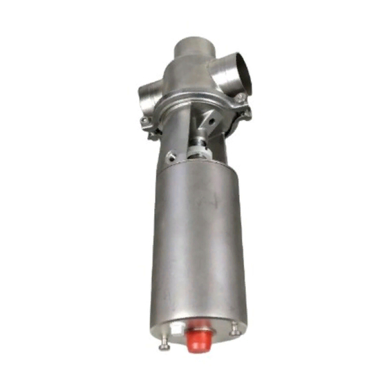
- Page 1 Instruction Manual Unique Single Seat Valve (DN125-150) ESE02590-EN3 2016-03 Original manual...
-
Page 3: Table Of Contents
Table of contents The information herein is correct at the time of issue but may be subject to change without prior notice 1. Declaration of Conformity ................2. Safety ....................2.1. Important information ................2.2. Warning signs ..................2.3. Safety precautions ................3. -
Page 4: Declaration Of Conformity
1 Declaration of Conformity Revision of Declaration of Conformity 2009-12-29 The Designated Company Alfa Laval Kolding A/S Company Name Albuen 31, DK-6000 Kolding, Denmark Address +45 79 32 22 00 Phone No. hereby declare that Valve Designation SRC PN10 Type... -
Page 5: Safety
2 Safety Unsafe practices and other important information are emphasized in this manual. Warnings are emphasized by means of special signs. 2.1 Important information Always read the manual before using the valve! WARNING Indicates that special procedures must be followed to avoid serious personal injury. CAUTION Indicates that special procedures must be followed to avoid damage to the valve. -
Page 6: Safety Precautions
2 Safety All warnings in the manual are summarized on this page. Pay special attention to the instructions below so that severe personal injury and/or damage to the valve are avoided. 2.3 Safety precautions Installation: Always observe the technical data (see chapter 6 Technical data) Always release compressed air after use. -
Page 7: Installation
The valve is assembled before delivery, if it is supplied with fittings. 3.1 Unpacking/delivery/general installation Unpacking/delivery Step 1 CAUTION Alfa Laval cannot be held responsible for incorrect unpacking. Check the delivery: 1. Complete valve, shut-off valve or change-over valve (see step 2 and 3) 2. Delivery note 3. Instruction Manual... -
Page 8: Recommended Auxiliary Equipment
3 Installation The valve sizes DN125-150 are very heavy. Therefore Alfa Laval recommends manufacturing and usage of auxiliary equipment. A proposal is given below. Please note that the auxiliary equipment cannot be supplied by Alfa Laval. The items refer to the parts list and service kits section. -
Page 9: General Installation
See chapter 6 Technical data Always release compressed air after use. CAUTION Alfa Laval cannot be held responsible for incorrect installation. Step 2 Never touch the clip assembly or the actuator piston rod if the actuator is supplied with compressed air (see the warning label). - Page 10 3 Installation Study the instructions carefully and pay special attention to the warnings! The valve has welding ends as standard but can also be supplied with fittings. NO = Normally open. NC = Normally closed. A/A = Air/air activated. Step 4 Avoid stressing the valve.
-
Page 11: Welding
3 Installation Study the instructions carefully. The valve is supplied as separate parts to facilitate the welding. The items refer to the parts list and service kits section. Check the valve for smooth operation after welding. NO = Normally open. NC = Normally closed. A/A = Air/air activated. 3.4 Welding Step 1 Always weld the valve so that the valve body seal ring can be replaced (change-over valve). - Page 12 3 Installation Study the instructions carefully. The valve is supplied as separate parts to facilitate the welding. The items refer to the parts list and service kits section. Check the valve for smooth operation after welding. NO = Normally open. NC = Normally closed. A/A = Air/air activated. Step 4 Air (NO/AA) Pre-use check...
-
Page 13: Operation
- Always read the technical data thoroughly (see chapter 6 Technical data) - Always release compressed air after use. CAUTION! Alfa Laval cannot be held responsible for incorrect operation. Step 2 Never touch the valve or the pipelines when processing hot liquids or when sterilizing. - Page 14 4 Operation Study the instructions carefully and pay special attention to the warnings! Ensure that the valve operates smoothly. The items refer to the parts list and service kits section. NO = Normally open. NC = Normally closed. A/A = Air/air activated. Step 5 Lubrication of actuator 1.
-
Page 15: Fault Finding
4 Operation Pay attention to possible faults. Study the instructions carefully. The items refer to the parts list and service kits section 4.2 Fault finding Repair Problem Cause/result The valve plug jerks The lealings seize Lubricate: - O-rings (2) - O-ring (5) and the inside of cylinder (3) - Lip seal (14) Product leakage - Worn/product affected lip seal (14) and/or... -
Page 16: Recommended Cleaning
4 Operation The valve is designed for cleaning in place (CIP). CIP = Cleaning In Place. Study the instructions carefully and pay special attention to the warnings! NaOH = Caustic Soda. HNO3 = Nitric acid. 4.3 Recommended cleaning Step 1 Caustic danger! Always handle lye and acid with great care. - Page 17 4 Operation The valve is designed for cleaning in place (CIP). CIP = Cleaning In Place. Study the instructions carefully and pay special attention to the warnings! NaOH = Caustic Soda. HNO3 = Nitric acid. Step 5 1. Avoid excessive concentration of the cleaning agent. 2.
-
Page 18: Maintenance
5 Maintenance Maintain the valve regularly. Study the instructions carefully and pay special attention to the warnings! Always keep spare rubber seals and lip seals in stock. 5.1 General maintenance Step 1 NOTE All scrap must be stored/discharged in accordance with current rules/directives. - Page 19 5 Maintenance Maintain the valve regularly. Study the instructions carefully and pay special attention to the warnings! Always keep spare rubber seals and lip seals in stock. Valve lip seal Product rubber seals Actuator rubber seals Replace after Replace after Replace when replacing the 12 months depending Preventive maintenance...
-
Page 20: Dismantling Of Valve
5 Maintenance Study the instructions carefully. The items refer to the parts list and service kits section. Handle scrap correctly. NC = Normally closed. NO = Normally open. A/A = Air/air activated. 5.2 Dismantling of valve Step 1 Change-over valve: 1. - Page 21 5 Maintenance Study the instructions carefully. The items refer to the parts list and service kits section. Handle scrap correctly. NC = Normally closed. NO = Normally open. A/A = Air/air activated. Step 5 Shut-off valve Change-over valve Shut-off valve: Remove lip seal (14) (For sizes DN125-150: Remove lip seal (14) and guide ring (27)).
-
Page 22: Valve Assembly
5 Maintenance Study the instructons carefully. The items refer to the parts list and service kits section. Lubricate the rubber seals and the lip seal beforefitting them. 5.3 Valve assembly Step 1 Shut-off valve Change-over valve 1. Assemble the complete valve plug 2. - Page 23 5 Maintenance Study the instructons carefully. The items refer to the parts list and service kits section. Lubricate the rubber seals and the lip seal beforefitting them. Step 4 Air (NO,A/A) Air (NO,A/A) 1. Fit the plastic ring of clip assembly (11) on the actuator piston 2.
-
Page 24: Dismantling Of Actuator
5 Maintenance Study the instructions carefully. The items refer to the parts list and service kits section. Handle scrap correctly. NO = Normally open. NC = Normally closed. A/A = Air/air activated. Service tool: See Spare Parts. 5.4 Dismantling of actuator Step 1 Rotate with the 1. -
Page 25: Assembly Of Actuator
5 Maintenance Study the instructions carefully. The items refer to the parts list and service kits section. Lubricate the rubber seals before fitting them. A larger actuator is available for valve sizes DN/OD38-63.5 mm. The spring assembly can be replaced by a stronger one. A/A = Air/air activated. -
Page 26: Technical Data
6 Technical data It is important to observe the technical data during installation, operation and maintenance. Inform the personnel about the technical data. NO = Normally open. NC = Normally closed. 6.1 Technical data The valve is remote-controlled by means of compressed air. It has few and simple moveable parts which results in a very reliable valve and low maintenance cost. -
Page 27: Drawings
7 Drawings It is important to observe the technical data during installation, operation and maintenance. Inform the personnel about the technical data. NO = Normally open. NC = Normally closed. 7.1 Drawings DN125-150 shut-off valve, DN125-150 change-over valve, see section 6.6 see section 6.7... -
Page 28: Parts List And Service Kits
8 Parts list and service kits It is important to observe the technical data during installation, operation and maintenance. Inform the personnel about the technical data. NO = Normally open. NC = Normally closed. 8.1 Shut-off valve TD 425-172_1... - Page 29 8 Parts list and service kits It is important to observe the technical data during installation, operation and maintenance. Inform the personnel about the technical data. NO = Normally open. NC = Normally closed. Parts list Pos. Denomination Actuator, complete ...
-
Page 30: Change-Over Valve
8 Parts list and service kits It is important to observe the technical data during installation, operation and maintenance. Inform the personnel about the technical data. NO = Normally open. NC = Normally closed. 8.2 Change-over valve Standard - change-over valve - DN125-150 TD 425-171_1... - Page 31 8 Parts list and service kits It is important to observe the technical data during installation, operation and maintenance. Inform the personnel about the technical data. NO = Normally open. NC = Normally closed. Parts list Pos. Denomination Actuator, complete ...
- Page 32 © Alfa Laval Corporate AB This document and its contents is owned by Alfa Laval Corporate AB and protected by laws governing intellectual property and thereto related rights. It is the responsibility of the user of this document to comply with all applicable intellectual property laws. Without limiting any rights related to this document, no part of this document may be copied, reproduced or transmitted in any form or by any means (electronic, mechanical, photocopying, recording, or otherwise), or for any purpose, without the expressed permission of Alfa Laval Corporate AB.
Need help?
Do you have a question about the SRC PN10 and is the answer not in the manual?
Questions and answers