Alfa Laval Unique 7000 Instruction Manual
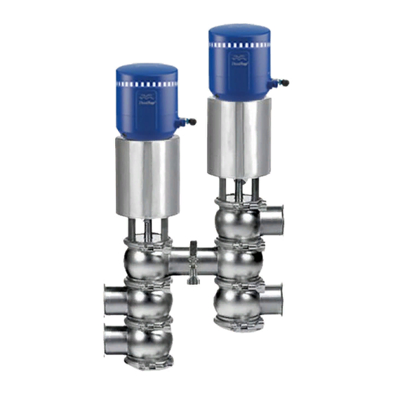
Flo-diversion valve
Hide thumbs
Also See for Unique 7000:
- Instruction manual (33 pages) ,
- Instruction manual (26 pages) ,
- Instruction manual (24 pages)
Table of Contents
Advertisement
Advertisement
Table of Contents

Subscribe to Our Youtube Channel
Related Manuals for Alfa Laval Unique 7000


Summary of Contents for Alfa Laval Unique 7000
- Page 1 Instruction Manual Unique 7000 Flo-Diversion Valve 2017-02...
-
Page 3: Table Of Contents
Thank you for purchasing an Alfa Laval Product! This manual contains installation, operation, and repair instructions, Flo-Diversion Valves designed and manufactured by Alfa Laval Inc. It also provides a troubleshooting chart to assist in determining electrical and mechanical malfunctions, if they should occur. -
Page 5: Introduction And Specifications
Introduction and specifications All warnings in the manual are summarized on this page. Pay special attention to the instructions below so that severe personal injury and/or damange to the valve are avoided. Installation - Always read the technical data thoroughly. - Always release compressed air after use. -
Page 6: Valve Assembly Nomenclature
Available with either TR2 or elastomer seat rings. RA valve, elastomer seat only. DETAIL B SCALE 1 : 1 Fully maintainable. Use valves with existing control panel or new Alfa Laval PLC control panel. Divert Position ('A' LED) Divert valve function. Both valve tops will have ”A”... -
Page 7: Actuator Specifications
Introduction and Specifications Actuator Specifications Reverse-Acting Valve Standard Valve pneumatic movement upwards pneumatic movement downward Air Supply Requirements Minimum Air Pressure: 70 PSI Air Presure Range: 70-100 PSI Air Volume Required: Air Consumption (In3 Free air) for one stroke Valve Size 1"... -
Page 8: Performance And Dimensions
Introduction and Specifications Performance and Dimensions Valve Size 1½" 2" 2½" 3" 20.78 22.8 24.32 26.13 2.39 2.91 3.89 2.95 2.94 3.73 3.93 5.96 5.94 7.52 7.92 Stroke .067 0.87 0.87 1.06 Pressure/Capacity Limits Performance Unique 7640 Valves Valve size Max. -
Page 9: Performance And Dimensions Reverse-Acting
Introduction and Specifications Performance and Dimensions Reverse-Acting Valve Size 2" 2½" 3" 4" 22.8 24.32 26.13 31.1 2.91 3.89 4.87 2.94 3.73 3.93 4.72 5.94 7.52 7.92 10.76 E Stem Up 51.1 56.9 63.5 76.7 E Stem Down 76.1 81.9 93.5 106.7 Stroke... -
Page 10: Installation
Installation Unpacking Equipment The Flo-Diversion Valve should be unpacked immediately upon receipt from the factory and carefully inspected for damage that may have occurred during shipping. The equipment should also be checked against the bill of lading to make sure there are no shortages. -
Page 11: Installation
Installation Pneumatic Connections with Solenoid in T-Top Pneumatic Connections with Solenoid in-top OUT 1A AIR IN Air to Actuator Supply Air With Solenoid in Top noid in T-Top enoid in T-Top Normally Closed RA with Solenoid in Top AIR IN Supply Air AIR IN Supply Air... -
Page 12: Electrical Connection, Internal
Installation Electrical connection, internal Output - Valve in Divert Flow PLC Inputs Input Solenoid 1 Legal PLC Output for Forward Flow Output - Valve in Forward Flow Supply + 24 VDC Supply - 24 VDC Power Supply Solenoid Common Earth Solenoid Common Wiring to internal solenoid Output Solenoid 1... -
Page 13: Operations
Operations Operating Modes The Flow Diversion device consists of two (2) valves. Each is a two-position, three-way valve connected by a common body. This common body is the upper body of the Divert Valve and the middle body of the Leak Detect Valve. The air-to-raise actuators of the two valves are connected to independent air supplies which cycle the valves to the three operating modes;... -
Page 14: Flush Mode
Operations Flush Mode In this mode, correctly pasteurized product flushes and clears the common body between the Divert Valve and the Leak Detect Valve, prior to initiating product Forward Flow. The flush time is controlled by a Flow Divert Valve controller. This control system is separate from the Divert and Leak Detect Valves, but works in conjunction with them. -
Page 15: Forward Flow Mode
Operations Forward Flow Mode Forward Flow is the final operating mode of the Flow Diversion Valve. Product flows through both valves to the cooling sections of the pasteurization system. For the Forward Flow mode to be maintained: 1. The legal set temperature must be maintained. 2. -
Page 16: Thinktop For Fdv Addendum
ThinkTop for FDV Addendum ThinkTop Indication Specifications ThinkTops use micro chip sensor technology which provides a more accurate position sensing than mechanical switches. The micro chips in the sensor, utilizing a principle called the Hall Effect, calculate the position of the indicating target to a very high degree of accuracy. -
Page 17: Valve Assembly Test And Sealing Instructions
ThinkTop for FDV Addendum Valve Assembly Test and Sealing Instructions The ThinkTop sensors on these valves are safety devices. They are adjusted so that the timing pump will not run, at sub-legal pasteurization temperatures, unless the valves are completely and properly assembled. Sealing wire To test the sensor adjustment: thumb screw... -
Page 18: Recommended Cleaning
Recommended Cleaning Recommended Cleaning The valve is designed for cleaning in place (CIP). CIP = Cleaning In Place. Study the instructions carefully and pay special attention to the warnings!NaOH = Caustic Soda. HNO3 = Nitric acid. - Page 19 Recommended Cleaning...
-
Page 20: Troubleshooting Guidelines
Troubleshooting Guidelines The Flo-Diversion valve is relatively maintenance free with the exception periodic inspection. As with any precision equipment, however, occasional problems can arise. The troubleshooting chart provides a means of determining and correcting most mechanical and electrical problems. Note: The troubleshooting chart is divided into two parts, one mechanical and electrical. -
Page 21: General Maintenance General Maintenance
General Maintenance General Maintenance Maintain the valve regularly. Study the instructions carefully and pay special attention to the warnings!Always keep spare rubber seals and lip seals in stock. Step 1 Always read the technical data thoroughly Always release the compressed air after use. Caution! All scrap must be stored/disposed of in accordance with current rules/directives. - Page 22 General Maintenance Step 4 Never touch the moving parts if the actuator is supplied with compressed air. Moving parts! Below are some guidelines for maintenance and lubrication intervals. Please note that the guidelines are for normal working conditions in one shift. Product wetted Actuator seals...
-
Page 23: Disassembly - Standard Flow Diversion Valve
9. Follow instructions for removal of plug seats/seals and replace - see instructions. 10. Reverse order and reassemble valve. Remember to tighten spindle and plug to a torque of 22 ft lb (used two 17mm wrenches) Alfa Laval recommends the using of Loctite no. 243. -
Page 24: Disassembly - Reverse-Acting Valve
13. Follow instructions for removal and replacement of plug seals - see instructions. 14. Reverse order and reassemble valve. Remember to tighten spindle and plug to a torque of 22 ft lb (used two 17mm wrenches) Alfa Laval recommends the using of Loctite no. 243. -
Page 25: Bushing And Seat/Seal Replacement
General Maintenance Bushing and seat/seal replacement TR2 and Elastomer seat ring replacement 1. Remove old seal ring using a knife, screwdriver or similar. Be careful not to damage metal parts. 2. Pre-mount plug seal without pressing it into the groove. 3. -
Page 26: Actuator Bushing Replacement
General Maintenance Actuator bushing replacement 1. Unscrew and remove top and bottom bushings with O-rings 2. Lubricate O-rings with Molykote Longterm 2 plus before fitting. 3. Fit bushings and O-rings. Tighten brushing with a torque = 7 lbf-ft (10Nm). Be careful not to overtighten. Dismantling of optional maintainable actuator 1. -
Page 27: Spare Parts List
Spare Parts List Unique 7000 Standard Flow Diversion Valve Exploded View Maintainable Actuator Refer to actuator spares page page 31 27.2 37.2 37.1 27.1 27.2 37.2... -
Page 28: Unique 7000 Standard Flow Diversion Valve Part Numbers
Spare Parts List Unique 7000 Standard Flow Diversion Valve Part Numbers Qty Denomination 1-½" 2" 2-½" 3" Clamp Clamp ............9612-9393-16 9612-9393-17 9612-9393-18 9612-9393-19 Bonnet Bonnet ............9613-1271-02 9613-1271-03 9613-1271-04 9613-1271-05 O-ring, EPDM ..........O-ring, HNBR ..........O-ring, FPM ........... O-ring, set (10 pcs.) EPDM ......9614-0594-22... -
Page 29: Reverse-Acting Valve Spares Exploded View
Spare Parts List Reverse-Acting Valve Spares Exploded View Maintainable Actuator Refer to actuator spares page page 31 34.2 34.1 34.3... -
Page 30: Reverse-Acting Valve Spare Part Numbers
Spare Parts List Reverse-Acting Valve Spare Part Numbers Qty Denomination 2" 2-½" 3" 4" Clamp Clamp ..............9612-9393-17 9612-9393-18 9612-9393-19 9612-9393-20 Bonnet Upper Bonnet ............. 9613-1271-03 9613-1271-04 9613-1271-05 9613-1271-06 O-ring, EPDM ............. O-ring, HNBR ............. O-ring, FPM ............O-ring, set (10 pcs.) EPDM ......... 9614-0594-25 9614-0594-28 9614-0594-31 9614-0594-34... -
Page 31: Failed Closed Actuator For Reverse Acting Exploded View
Spare Parts List Failed Closed Actuator for Reverse Acting Failed Open Actuator for Standard Exploded View Exploded View (116) (116) -
Page 32: Unique 7000 Maintainable Actuator - Flow Diversion Valve Part Numbers
Spare Parts List Unique 7000 Maintainable Actuator - Flow Diversion Valve Part Numbers Qty Denomination 1-½" 2" 2-½" 3" 4" Actuator Actuator, - complete (NC) ..NA 9634-0938-01 9634-0938-02 9634-0938-03 9634-0938-04 Actuator, - complete (NO) ..9634-0938-05 9634-0938-06 9634-0938-07 9634-0938-08 Cylinder, (polished) .... -
Page 33: Thinktop Exploded View
Spare Parts List ThinkTop Exploded View ThinkTop for 7000 FDV. Digital top with or without (1) solenoid. Standard parts except for special magnet assembly. Magnet assembly allows insert of "test gauge" to change setting position. Also, eyelet cover screws allows (position 2) the addition of seal wire to secure top and to be added by inspector. -
Page 34: Thinktop Part Numbers
Spare Parts List ThinkTop Part Numbers Qty Denomination Description ThinkTop Complete, 0SOL Digital 24VDC ........9634-0939-01 ThinkTop Complete, 1SOL Digital 24VDC ........9634-0939-02 Shell complete ..................9613-4279-01 Tamper proof screw ................9634-0910-01 Screw ....................9611-9934-58 Washer .....................9611-9934-59 Sensor board, Digital 8-30 VDC PNP/NPN ........9613-4434-01 Solenoid valve, 3/2, 24 VDC .............9611-9933-24 PT screw ..................9611-9934-57 Base, complete, no solenoids ............9613-4282-01 (Pos. - Page 35 (electronic, mechanical, photocopying, recording, or otherwise), or for any purpose, without the expressed permission of Alfa Laval Corporate AB. Alfa Laval Corporate AB will enforce its rights...
Need help?
Do you have a question about the Unique 7000 and is the answer not in the manual?
Questions and answers