
Related Manuals for Alfa Laval ARC series


Summary of Contents for Alfa Laval ARC series
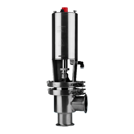
- Page 1 Instruction Manual ARC with reduced stroke Aseptic Remote-Controlled Valve IM70815-/ 8 ¦ ² ¾ ³ ¾ ½ ¾ ¦ IM70815EN 2010-03...
- Page 2 1 EC Declaration of Conformity...
-
Page 3: Table Of Contents
Table of contents This manual is divided into main sections. - See below. 1. Important information ........2 Safety 2. Warning signs ..........2 3. Safety precautions ........3 1. Unpacking/Delivery ........4 Installation 2. General installation ........5 3. Welding ............6 4. -
Page 4: Important Information
Safety Unsafe practices and other important information are Warnings are emphasized by means of special signs. emphasized in this manual. 1. Important information Always read the manual before using the valve! Indicates that special procedures must be fol- WARNING! lowed to avoid severe personal injury. Indicates that special procedures must be fol- CAUTION! lowed to avoid damage to the valve. -
Page 5: Safety Precautions
Safety All warnings in the manual are summarized on this Pay special attention to the instructions below so that page. severe personal injury and/or damage to the valve are avoided. 3. Safety precautions Installation: - Always read the technical data thoroughly (see page 20). -
Page 6: Unpacking/Delivery
Installation The instruction manual is part of the delivery. The valve is supplied as separate parts as standard Study the instructions carefully. (for welding). The items refer to the drawings and the parts list on The valve is assembled before delivery, if it is pages 22-29. -
Page 7: General Installation
Installation Study the instructions carefully and pay special NO = Normally open. attention to the warnings! NC = Normally closed. The valve has welding ends as standard but can also A/A = Air/air activated. be supplied with fittings. 2. General installation - Always read the technical data thoroughly (see page 20). -
Page 8: Welding
Installation Study the instructions carefully. The items refer to the drawings and the parts list on The valve is supplied as separate parts to facilitate pages 22-29. the welding. Check the valve for smooth operation after welding. 3. Welding Change-over valve Stop valve (upper valve body) Always weld the valve so that the valve body seal... -
Page 9: Fitting Of Oil Damper (Optional Extra)
Installation The valve can be fitted with an oil damper if water Study the instructions carefully and pay special hammer occurs when the valve closes in the flow attention to the warnings! direction. NC = normally closed A/A = air/air activated 4. -
Page 10: Fitting Of Indication Equipment (Optional Extra)
Installation The valve can be fitted with the top units LKT-N and Study the instructions carefully and pay special LKT-S. It can also be fitted with an indication unit. attention to the warnings! 5. Fitting of indication equipment (optional extra) LKT-N LKT-S Indication unit... -
Page 11: Operation
Operation Study the instructions carefully and pay special The items refer to the drawings and the parts list on attention to the warnings! pages 22-29. Ensure that the valve operates smoothly. 1. Operation Burning danger! - Always read the technical data thoroughly (see page 20). -
Page 12: Fault Finding
Operation Pay attention to possible faults. Study the instructions carefully. The items refer to the drawings and the parts list on pages 22-29. 2. Fault finding NOTE! Study the maintenance instructions carefully before replacing worn parts. - See page 12! Problem Cause/result Repair... -
Page 13: Recommended Cleaning
Operation The valve is designed for cleaning in place (CIP). Study the instructions carefully and pay special CIP = Cleaning In Place. attention to the warnings! NaOH = Caustic Soda. = Nitric acid. 3. Recommended cleaning Caustic danger! Burning danger! Always use Always use rubber gloves! -
Page 14: General Maintenance
Maintenance Maintain the valve carefully. Always keep spare rubber seals and diaphragms in Study the instructions carefully and pay special stock. attention to the warnings! 1. General maintenance Burning - Always read the technical data danger! Atmospheric thoroughly (see page 20). pressure - Always release compressed air after required! - Page 15 Maintenance Maintain the valve carefully. Always keep spare rubber seals and diaphragms in Study the instructions carefully. stock. Check the valve for smooth operation after service. 1. General maintenance Valve Valve Actuator diaphragm unit rubber seals rubber seals Preventive Replace when Replace after Replace after maintenance...
-
Page 16: Dismantling Of Valve
Maintenance Study the instructions carefully. Handle scrap correctly. The items refer to the drawings and the parts list on NC = Normally closed. pages 22-29. NO = Normally open. A/A = Air/air activated. 2. Dismantling of valve NO actuator: NC actuator: Remove upper clamp (15). - Page 17 Maintenance Handle scrap correctly. Study the instructions carefully. NC = Normally closed. The items refer to the drawings and the parts list on pages 22-29. NO = Normally open. A/A = Air/air activated. 2. Dismantling of valve Turn upper stem (19) anticlockwise and remove Remove diaphragm (20a), diaphragm (20b) it from lower stem (22a), (counterhold with a and stem seal (20d) from lower stem (22a).
-
Page 18: Reassembly Of Valve
Maintenance Study the instructions carefully. Lubricate the rubber seals and the diaphragms be- fore fitting them. The items refer to the drawings and the parts list on pages 22-29. 3. Reassembly of valve Change-over valve: Fit seal (22b), middle piece (22c) and seal Stop valve: Fit seal (22d) on lower stem (22a). - Page 19 Maintenance Study the instructions carefully. Lubricate the rubber seals and the diaphragms be- The items refer to the drawings and the parts list on fore fitting them. pages 22-29. 3. Reassembly of valve Correct! Wrong! Fit the complete diaphragm/stem unit in valve Change-over valve: body (16 or 18).
-
Page 20: Dismantling Of Actuator
Maintenance Study the instructions carefully. Handle scrap correctly. The items refer to the drawings and the parts list on A/A = Air/air activated. pages 22-29. 4. Dismantling of actuator Turn by hand or with the service tool! Turn cylinder (3). Remove cylinder (3). -
Page 21: Reassembly Of Actuator
Maintenance Study the instructions carefully. A larger actuator is available. The items refer to the drawings and the parts list on The spring assembly can be replaced with a stronger pages 22-29. one. Lubricate the rubber seals before fitting them. A/A = Air/air activated. -
Page 22: Technical Data
- At end of use, the equipment shall be recycled according to relevant, local regulations. Beside the equipment itself, any hazardous residues from the process liquid must be considered and dealt with in a proper manner. When in doubt, or in the absence of local regulations, please contact the local Alfa Laval sales company. -
Page 24: Parts List
Drawing/Parts list The drawings and the parts list include all items. The items are identical with the items in the Spare NO = Normally open. Parts List. NC = Normally closed. When ordering spare parts, please use the Spare Parts List! Parts list ARC with reduced stroke, stop valve Item... -
Page 25: Exploded Drawing
Drawing/Parts list This page shows an exploded drawing of ARC with The drawing includes all items of the valve. reduced stroke, stop valve. They are identical with the items in the Spare Parts List Exploded drawing Mounting bracket... -
Page 26: Arc With Reduced Stroke
Drawing/Parts list The drawings and the parts list include all items. The items are identical with the items in the Spare NO = Normally open. Parts List. NC = Normally closed. When ordering spare parts, please use the Spare Parts List! Parts list ARC with reduced stroke, stop valve Item... - Page 27 Drawing/Parts list The drawings below show ARC with reduced stroke, The items refer to the parts list on the opposite part stop valve. of the page. Drawings...
- Page 28 Drawing/Parts list The drawings and the parts list include all items. The items are identical with the items in the Spare NO = Normally open. Parts List. NC = Normally closed. When ordering spare parts, please use the Spare Parts List! Parts list ARC with reduced stroke, change-over valve Item...
- Page 29 Drawing/Parts list This page shows an exploded drawing of ARC with The drawing includes all items of the valve. reduced stroke, change-over valve. They are identical with the items in the Spare Parts List. Exploded drawing Mounting bracket...
- Page 30 Drawing/Parts list The drawings and the parts list include all items. The items are identical with the items in the Spare NO = Normally open. Parts List. NC = Normally closed. When ordering spare parts, please use the Spare Parts List! Parts list ARC with reduced stroke, change-over valve Item...
- Page 31 Drawing/Parts list The drawings below show ARC with reduced stroke, The items refer to the parts list on the opposite part change-over valve. of the page. Drawings...
-
Page 32: Oil Damper
Drawing/Parts list The drawings and the parts list include all items. The items are identical with the items in the Spare NO = Normally open. Parts List. NC = Normally closed. When ordering spare parts, please use the Spare Parts List! Parts list Oil damper for ARC with reduced stroke (optional extra) Item... - Page 33 Drawing/Parts list This page shows an exploded drawing of the oil The drawing includes all items of the valve. damper for ARC with reduced stroke. The damper is They are identical with the items in the Spare Parts an optional extra. List.
- Page 34 Drawing/Parts list The drawings and the parts list include all items. The items are identical with the items in the Spare NO = Normally open. Parts List. NC = Normally closed. When ordering spare parts, please use the Spare Parts List! Parts list Oil damper for ARC with reduced stroke (optional extra) Item...
-
Page 35: Oil Damper
Drawing/Parts list The drawing below shows the oil damper for ARC The items refer to the parts list on the opposite part with reduced stroke. of the page. The damper is an optional extra. Drawing... - Page 36 How to contact Alfa Laval Contact details for all countries are continually updated on our website. Please visit www.alfalaval.com to access the information direct.
Need help?
Do you have a question about the ARC series and is the answer not in the manual?
Questions and answers