Table of Contents
Advertisement
Quick Links
X-ray
Sources
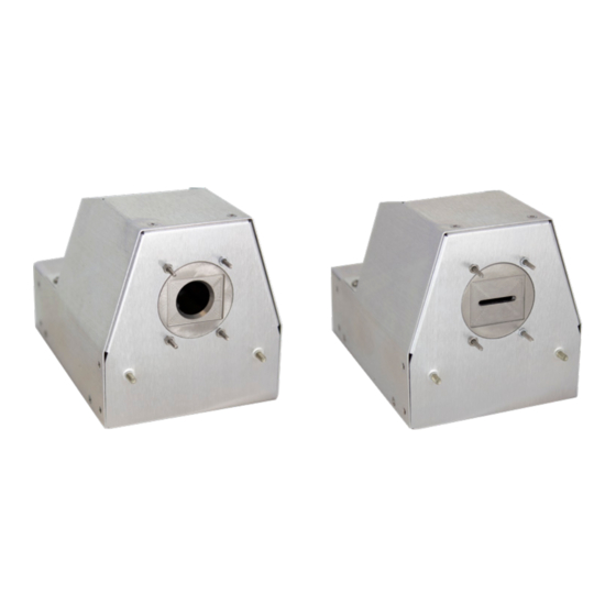
Figure 1: Fan Beam/Cone Beam
Table of Contents
•
Introduction
•
•
•
•
•
•
•
•
•
•
•
•
MOXTEK
®
Introduction
Moxtek manufactures low-power miniature X-ray sources for a variety
of applications including handheld XRF, Security, NDT and benchtop
instruments. Moxtek sources are small, lightweight and can be packaged
into customer enclosures. MOX140G is ideally configured for backscatter
and traditional imaging. MOX140G is capable of running up to 140kV
and 7W.
1
MOX140G
Operation Manual
1
2
2
2
2
3
3
3-4
3-4
5
6
7-9
10
TUB-MAN-1022 Rev A
Subject to technical change without notice
Advertisement
Table of Contents

Related Manuals for MOXTEK X-ray Sources


Summary of Contents for MOXTEK X-ray Sources
-
Page 1: Table Of Contents
Sources Operation Manual Introduction Moxtek manufactures low-power miniature X-ray sources for a variety of applications including handheld XRF, Security, NDT and benchtop instruments. Moxtek sources are small, lightweight and can be packaged into customer enclosures. MOX140G is ideally configured for backscatter and traditional imaging. -
Page 2: X-Ray Source Characteristics
Removal of more than two studs will void the warranty. Once removed, studs cannot be added back due to a risk in puncturing potting and harming electronic components. Figure 2: Mounting Points Diagram MOXTEK TUB-MAN-1022 Rev A ®... -
Page 3: Initial Inspection
If using the adapter board, proceeed to software section. Electrical Interface The Samtec 10-pin FLE-105-01-G-DV connector is not used. This is for Moxtek use only. See Figure 3 below. The Moxtek uses a Molex Picoblade connector # 53398-1271 (12-pins) is used to interface with MOX140G. -
Page 4: I2C Information
(if they are larger than 1 byte). So for example, on ctrl_vBrdTemp, user would read the two bytes starting at 0x0F. Because data is stored little-endian format, byte 0x10 is the most significant byte (MSB), so it is shifted up by 8 and added to byte 0x0F. MOXTEK TUB-MAN-1022 Rev A ®... -
Page 5: Operating Precautions And Warnings
0.5 seconds. The suggested procedure is to turn the source on at 70KV and 20uA, then take 10KV steps up to 140KV. Finally turn the filament power up to full output. This should take about 0.5 seconds. MOXTEK TUB-MAN-1022 Rev A ®... -
Page 6: Software And Setup
11. Run the “140kV PC Controller.application” file 12. Once the 140kV PC Controller software is installed, run the program 13. A taskbar search for “140kV PC Controller” can locate the new file if needed Figure 4: Moxtek Website Software Downloads Page MOXTEK TUB-MAN-1022 Rev A ®... -
Page 7: Running The 140Kv Pc Controller Application
7. A green light should turn on, which confirms power is being provided, and a red light, meaning the safety interlock is closed. The unit is ready to run. Figure 7: Safety Interlock Closed TUB-MAN-1022 Rev A MOXTEK ® Subject to technical change without notice... - Page 8 “Std Ramp” to 140 KV/s for a 1 second ramp time to full power, or check the “Fast Ramp” option, with 600 KV/s and 70 KV for the “Switch” value, and it will ramp to full power in 0.5 seconds. MOXTEK TUB-MAN-1022 Rev A ®...
- Page 9 “On Time” recommended is 30s. The corresponding minimum recommended “Off Time” is 30s. The “Add 20uA above 50KV” box should remain checked, and the “Filament Only” box should be blank. If more details on these settings are needed, contact Moxtek. MOXTEK TUB-MAN-1022 Rev A ®...
-
Page 10: Suggested Settings And Operation Parameters
At full output, the source should be set to 140KV and 50uA. 50uA should be the maximum current setting for the source at any KV level. • Active cooling is recommended to keep the temperature down on the source. MOXTEK TUB-MAN-1022 Rev A ® Subject to technical change without notice...
Need help?
Do you have a question about the X-ray Sources and is the answer not in the manual?
Questions and answers