Table of Contents
Advertisement
Quick Links
Advertisement
Table of Contents

Related Manuals for Kistler 2629DK


Summary of Contents for Kistler 2629DK
- Page 1 Instruction Manual TDC Sensor System Type 2629DK 2629DK_002-819e-09.18...
- Page 2 Instruction Manual TDC Sensor System Type 2629DK 2629DK_002-819e-09.18...
- Page 4 Foreword Foreword We thank you for choosing a Kistler quality product distin- guished by technical innovation, precision and long life. Information in this document is subject to change without notice. Kistler reserves the right to change or improve its products and make changes in the content without obliga- tion to notify any person or organization of such changes or improvements.
-
Page 5: Table Of Contents
TDC Sensor System Type 2629DK Content Introduction ..........................3 TDC Sensor System introduction ....................4 Important notes / protection of the instruments ..............5 For your safety ........................5 Disposal instructions for electronic equipment ..............5 Structure of the TDC Sensor System ..................6 Installation of the TDC Sensor System ..................7 Mounting the TDC probe ....................7... -
Page 6: Introduction
It will help you with the installation, maintenance, and use of this product. To the extent permitted by law Kistler does not accept any liability if this instruction manual is not followed or pro- ducts other than those listed under Accessories are used. -
Page 7: Tdc Sensor System Introduction
If, after studying these instructions, there are particular questions, which you wish to have answered, then the worldwide Kistler customer service is available to you. lt is also competent to advise you on how to deal with applica- tion-specific problems. -
Page 8: Important Notes / Protection Of The Instruments
Do not discard old electronic devices in municipal trash. For disposal at end of life, please return this product to an authorized local electronic waste disposal service or contact the nearest Kistler sales office for return instructions. 2629DK_002-819e-09.18 Page 5... -
Page 9: Structure Of The Tdc Sensor System
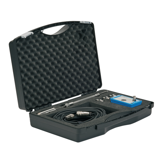
TDC Sensor System Type 2629DK 4. Structure of the TDC Sensor System The TDC Sensor System consists of ƒ TDC probe with integrated signal amplifier ƒ TDC electronic ƒ Mains cable ƒ Cable for TDC probe ƒ Installation adapters ƒ Instrument rod and adjuster rings... -
Page 10: Installation Of The Tdc Sensor System
Installation of the TDC Sensor System 5. Installation of the TDC Sensor System Install the measuring set-up, described above, in ac- cordance with the following instructions: 5.1 Mounting the TDC probe The installation adapter is mounted together with the TDC probe in the bore of a spark plug or glow plug bore. - Page 11 TDC Sensor System Type 2629DK TDC probe with integrated signal amplifier Adjuster rings Locking screw TDC probe tip Instrument rod Installation adapter Fig. 3: Assembly of TDC probe ƒ Step 2: Screw the instrument rod on to the installation adapter without firm tightening ƒ...
- Page 12 Installation of the TDC Sensor System ƒ Step 5: Insert the TDC probe into the instrument rod and in- stallation adapter until the probe tip touches the piston top, see Fig. 4 ƒ Step 6: Secure the TDC probe by tightening the instrument rod hand tight ƒ...
-
Page 13: Installation Of The Tdc Electronic
TDC Sensor System Type 2629DK 6. Installation of the TDC electronic Connect the power plug of the TDC electronic to a 110 or 230 Volt ~ 50 ... 60 Hz power supply by using the mains- connecting cable supplied. At the 5-pole socket (1), the amplified signal is connected to the TDC electronic. - Page 14 Installation of the TDC electronic Before starting the measurement for TDC determination, power OFF and ON the TDC electronic for an automated offset adjustment of the TDC signal. The assembly pro- cedure is complete and the measuring system is ready to perform.
-
Page 15: Tdc Determination With Tdc Sensor System
TDC Sensor System Type 2629DK 2629DK0 TDC Sensor System 7. TDC determination with TDC Sensor System TDC Signal / TDC Probe Distance 0,7 mm 0,8 mm 0,9 mm 1,0 mm Cylinder Pressure 1,2 mm 1,5 mm TDC Signals 2,5 mm... -
Page 16: Principle Of Capacitive Tdc Determination
Principle of capacitive TDC determination 8. Principle of capacitive TDC determination The principle of capacitive TDC determination is based on the fact that the sensor capacitance varies during the piston movement. The TDC probe tip and the piston top surface form a plate capacitor which is charged up to a re- ference voltage. -
Page 17: Technical Data
TDC Sensor System Type 2629DK 9. Technical data 9.1 TDC probe with integrated signal amplifier, Type 2629D10/2629D11 TDC probe with integrated signal amplifier, Types 2629D10/2629D11 Principle Capacitive-voltage converter μs Signal delay <3 (@ bandwidth 200 kHz) Output 0 ... 10... -
Page 18: Tdc Electronic, Type 2629D20
Technical data 9.2 TDC electronic, Type 2629D20 TDC electronic Type 2629D20 Power supply 100 ... 115/200 ... 240 50 ... 60 Fuse Protection class Operating temperature, max. °C <80 Connection Power plug IEC 320 C 14 Signal output BNC (neg.) Sensor input 5 pin Iinterface Dimensions (LxBxH) -
Page 19: Warranty
TDC Sensor System Type 2629DK 10. Warranty Regarding the warranty reference is made to the agree- ment between the respective contracting parties. Page 16 2629DK_002-819e-09.18... -
Page 20: Appendix
Kistler Instrumente AG, Winterthur Winterthur, February 2018 i.V. D. Müller Head of Electronics Products Lines 1 / 1 www.kistler.com 200.024.596 - a - YCE - Zertifikat - öffentlich - Freigegeben --- siehe Tabelle --- 29-Aug-2018 13:46 (CET) - Kle@int.kistler.com 2629DK_002-819e-09.18 Page 17...
Need help?
Do you have a question about the 2629DK and is the answer not in the manual?
Questions and answers