Advertisement
Quick Links
I N S T R U C T I O N S
OJ-Air2-WP55
67621 04/16 - (OSH)
• English
• Deutsch
• Français
• Svenska
• Norsk
• Dansk
English
LIST OF FIGURES
The following figures are located at the back of
the instructions:
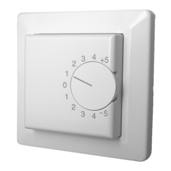
Fig. 1: Product, dimensioned sketch
Fig. 2: Mounting holes, dimensioned sketch
Fig. 3: Terminal overview
Fig. 4: Detachment of selector dial
Fig. 5:
Overview of product parts
INTRODUCTION
Read this manual thoroughly and follow the
instructions it contains before taking OJ-Air2-
WP55 into use.
OJ-Air2-WP55 can be used to advantage in an
OJ-Air2 system for room temperature measure-
ment and for setpoint offsetting of the desired
room temperature or inlet temperature in a
ventilation system.
In an OJ-Air2 system, the function is already
integrated into the software and simply needs
to be selected from the built-in WEB interface in
the OJ-Air2 system.
OJ-Air2-WP55 can, for example, be mounted
on the wall of the room that is to be controlled.
OJ-Air2-WP55 can be used to advantage in for
example educational and office environments
as well as similar rooms where it is desired that
the temperature be able to be adjusted by the
occupants of the room.
PRODUCT LINE
TYPE
PRODUCT
OJ-Air2-WP55
Combined room sensor and
potentiometer
KEY TO SYMBOLS
Particular attention should be paid to the sec-
tions in these instructions which are marked
with symbols and warnings.
Warning
This symbol is used where there is a risk of
severe or fatal personal injury.
Caution
This symbol is used where potentially danger-
ous situations may result in minor or moderate
personal injury. The symbol is also used to warn
against unsafe and hazardous conditions.
Note
This symbol is used to indicate important
information and in situations which may result in
serious damage to equipment and property.
FUNCTION
OJ-Air2-WP55 is furnished with a built-in room
sensor (PT1000) as well as a selector dial for
offsetting the temperature setpoint in an OJ-Air2
ventilation system. The product is furnished with
ventilation openings at the top and bottom in
order for the room sensor to be able to measure
the correct room temperature.
Using the product's selector dial, the user
can offset the desired setpoint for the room
temperature or inlet temperature in a ventilation
system (+/-5°C).
OJ-Air2-WP55 is furnished with the following
scale -5°C < 0°C > +5°C, which symbolises the
maximum temperature range within which the
setpoint can be offset by means of the OJ-Air2-
WP55.
The -5°C means that the setpoint is being
lowered, and the +5°C means that the setpoint
is being raised by 5°C in relation to the value set
for the OJ-Air2 system. Example: If the desired
setpoint for the room temperature in the OJ-Air2
control system is set to 23.0°C, then setting the
selector dial on OJ-Air2-WP55 to, for example,
-2°C will offset the temperature setpoint in the
OJ-Air2 system to 21.0°C, and that will now be
the new temperature setpoint that the system
will strive to maintain.
The output voltage (0-10 V DC) of OJ-Air2-
WP55 on terminals ø3 and ø4 (see Fig. 3) is
proportional to the selector dial's position.
When the selector dial is positioned at -5°C,
then the output voltage at terminals ø3 and ø4
= 0.0 V DC.
With the selector dial at the middle position of
0°C, the output voltage = 5.0 V DC, and with
the selector dial at the +5°C position, the output
voltage = 10.0 V DC.
INSTALLATION
If the internal temperature sensor in
OJ-AIR2-WP55 is used for measuring the
room temperature, then OJ-AIR2-WP55
must be mounted on the wall approx.
1.6-1.8 m above floor level and such that
there is free air circulation around the
product in order to attain optimum
measurement and regulation of the room
temperature. Avoid placing OJ-AIR2-
WP55 in draughts or direct sunlight.
If the internal PT1000 temperature sensor
in OJ-AIR2-WP55 is not being used, then
no special requirements are posed for the
placement of OJ-AIR2-WP55. It must be
ensured however that the product is
installed with respect to local and
international supervisory authority
requirements and installation principles
such as enclosure rating requirements.
Open OJ-AIR2-WP55 by carefully
detaching the selector dial (see Fig. 5, A).
The selector dial can possibly be loos-
ened with the point of a knife, a flat-blade
screwdriver or the like (see Fig. 4).
Once the selector dial has been detached,
the screw (see Fig. 5, B) holding the top
part to the back cover becomes visible.
Loosen this screw by turning it counter-
clockwise with a Phillips screwdriver.
Remove the top part (see Fig. 5, C).
© 2016 OJ Electronics A/S
^
^
^
^
Once the top part has been removed,
the front frame (see Fig. 5, E) can also be
removed.
OJ-AIR2-WP55 is now ready to be
mounted on the wall structure.
The mounting holes on the product's back
cover must always be used for fastening
the product to the wall (see Fig. 2).
To avoid short-circuits in the product, no
design modifications may be made to the
product. New holes must not be made in
the back cover of the product for
fastening purposes.
Depending upon the design of the wall,
it may be beneficial to use rawl plugs in
concrete and stone structures.
For electrical installation, OJ-AIR2-WP55 is
furnished with a terminal strip for wires of max.
1.5 mm
cross-sectional area (see Fig. 3). The
2
power supply is 24 V AC/DC and must be con-
nected to terminal strip terminals ø1 (L1/+24 V
DC) and ø2 (N/-GND) (see Fig. 3).
The variable output signal (0-10 V DC), which
is connected to the selector dial, must be con-
nected to terminal strip terminals ø3 – (GND)
and ø4 (+) (see Fig. 3). On the OJ-Air2Master,
this signal is connected to analogue input ø12
or ø13(+) and ø14 (–/GND).
If it is desired to use the built-in PT1000 sensor
element, then this signal must be connected
to terminal strip terminals ø5 and ø6. It is not a
precondition for the functionality of the product
that the built-in PT1000 sensor element be
used.
When OJ-AIR2-WP55 has been mounted on
the wall, and all electrical connections mounted
correctly, then OJ-AIR2-WP55 can be put back
together again.
Check that all electrical connections are
correctly fastened, and that all wires are
inside the frame so that the top part can
be freely mounted without pinching any
wires. Start by carefully placing the front
frame (see Fig 5, E) on top of the back
cover.
Hold the front frame firmly against the back
cover with one hand while placing the top part
(see Fig. 5, C) on top of the front frame with the
other hand. Tighten the screw (see Fig. 5, B)
again. The selector dial (Fig. 5, A) can now be
mounted again.
In order for the scale to be appropriate, it
is important that the potentiometer (see
Fig. 5, D) be set in the middle position
(horizontal) precisely as shown in Fig. 5.
Once you have made sure that the potentiom-
eter's selector dial is set as shown in Fig. 5,
D, then the selector dial (Fig. 5, A) can be set
on again and carefully pressed into place. The
line printed on the selector dial must be placed
horizontally, so it points precisely towards the
middle position (0°C).
ADJUSTMENT
If the scale on the front and the expected output
signal do not correspond, then the selector dial
can be offset.
Start by carefully detaching the selector dial
(see Fig. 5, A).
K
K
1
Advertisement

Related Manuals for OJ Electronics OJ-Air2-WP55


Summary of Contents for OJ Electronics OJ-Air2-WP55
- Page 1 The output voltage (0-10 V DC) of OJ-Air2- or ø13(+) and ø14 (–/GND). OJ-Air2-WP55 can be used to advantage in an WP55 on terminals ø3 and ø4 (see Fig. 3) is If it is desired to use the built-in PT1000 sensor OJ-Air2 system for room temperature measure- proportional to the selector dial's position.
-
Page 2: Installation
Boden auf der Wand zu befestigen, und direction in which the adjustment needs OJ-Air2-WP55 kann z. B. in dem zu steuernden zwar so, dass freie Luftzirkulation rund um to be performed, before putting the Raum auf der Wand montiert werden. OJ-Air2- das Produkt für eine optimale Messung... - Page 3 La tension de sortie (0-10 V CC) aux bornes ø3 Sollten die Frontskala und das erwartete Aus- Lisez entièrement ce manuel et suivez ses et ø4 de l’OJ-Air2-WP55 (voir Fig. 3) est pro- gangssignal nicht übereinstimmen, kann der instructions avant de mettre en service l’OJ- portionnelle à...
- Page 4 OJ-Air2-styrsystemet är maintenant être remis en place. pements électriques et électroniques inställt på 23,0 °C, kommer en inställning med ratten på OJ-Air2-WP55 på t.ex. -2 °C att för- Afin que l’échelle soit appropriée, il est Normes appliquées skjuta temperaturbörvärdet i OJ-Air2-systemet important que le potentiomètre (voir...
- Page 5 OJ-Air2-WP55 i bruk. INSTALLASJON (0 °C). OJ-Air2-WP55 kan med fordel benyttes i et OJ- Hvis den interne temperaturføleren i Air2-system for måling av romtemperaturen og OJ-AIR2-WP55 benyttes for måling av JUSTERING for settpunktforskyvning for ønsket romtem-...
- Page 6 Når overdelen er fjernet, kan forrammen (se fig. 5, E) også fjernes. SERVICE OG VEDLIKEHOLD Advarsel OJ-AIR2-WP55 er nå klar til å bli montert Ventilasjonsåpninger må holdes fri for støv og Dette symbol anvendes, hvor der er potentiel på veggkonstruksjonen.
-
Page 7: Miljø Og Bortskaffelse
Når overparten er fjernet, kan forrammen Dimensioner ......84 x 84 x 29 mm (se Fig. 5, E) også fjernes. Kapsling ............IP 30 OJ-AIR2-WP55 er nu klar til at blive mon- teret på vægkonstruktionen. SERVICE OG VEDLIGEHOLD Ventilationsåbninger skal holdes fri for støv og Monteringshullerne på... - Page 8 OJ ELECTRONICS A/S Stenager 13B · DK-6400 Sønderborg Tel. +45 73 12 13 14 · Fax +45 73 12 13 13 oj@ojelectronics.com · www.ojelectronics.com The trademark is a registered trademark belonging to OJ Electronics A/S · © 2016 OJ Electronics A/S...
Need help?
Do you have a question about the OJ-Air2-WP55 and is the answer not in the manual?
Questions and answers