
Related Manuals for OJ Electronics ETOP-4770


Summary of Contents for OJ Electronics ETOP-4770
- Page 1 OJ Winterline ® OJ Winterline ® 67694C 08/19 ALM ETOP-4770 Manual Ice & Snow Melting Controller for Outdoor Conditions > WWW.OJELECTRONICS.COM Contents © 2019 OJ Electronics A/S...
- Page 2 3 3 External Sensors and Remote Controller 8 1 Controller - ETOP-4770 3 3 1 Ground sensor - ETOG 8 1 Controller - ETOP-4770 (continued) 3 3 2 Gutter sensor - ETOR 8 2 Ground sensor – ETOG 3 3 3 Outdoor sensor – ETF-744/99...
- Page 3 The controller can be used together with the ETOG ground sensor or ETOR gutter sensor with temperature sensor ETF-744/99 The controller can also be controlled remotely from the ETOP-R control panel, placed inside the building < > PAGE 3 Contents © 2019 OJ Electronics A/S...
- Page 4 Sensors and Accessories ETOG-55 Ground sensor for detecting temperature and moisture ETOG-56/ETOK-1 Embedded ground sensor for detecting temperature and moisture ETOR-55 Gutter sensor for detecting moisture ETF-744/99 Outdoor sensor for detecting temperature < > PAGE 4 Contents © 2019 OJ Electronics A/S...
- Page 5 It is important that system settings and sensor choice is aligned Gutter, roof and downpipe applications Use the controller ETOP-4770 together with the gutter sensor ETOR-55 and the outdoor temperature sensor ETF-744/99 The ETOR sensor is designed for installation in gutters, downpipes, etc the ETOR...
- Page 6 When the moisture status is cleared, the system will continue heating the area for the “after run” time All modes can be overwritten by forced heating A test mode can be entered for system testing < > PAGE 6 Contents © 2019 OJ Electronics A/S...
-
Page 7: Important Safety Instructions
• Installation must be carried out by qualified personnel in accordance with appropriate regulations (where required by law) • The installation must comply with the national and/or local electrical codes < > PAGE 7 Contents © 2019 OJ Electronics A/S... -
Page 8: Environment And Recycling
All trademarks in this material are the property of the respective companies OJ and the OJ logotype are trademarks of OJ Electronics A/S All rights reserved ENVIRONMENT AND RECYCLING Protect the environment by disposing of the package in compliance with local... -
Page 9: Installation
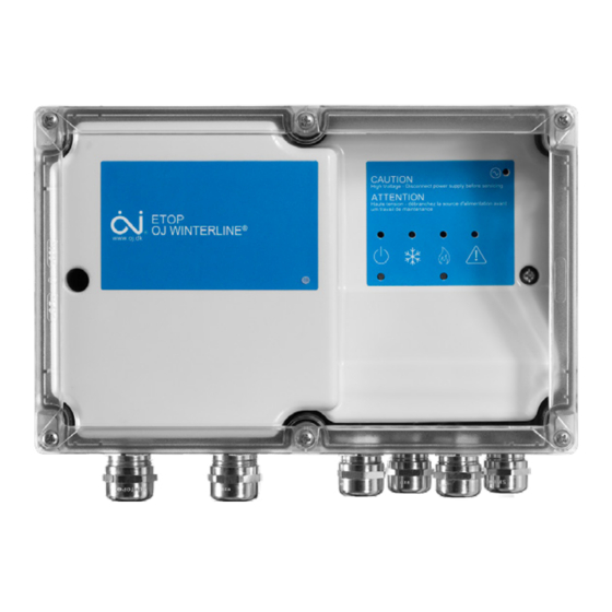
OJ Winterline ® 3 Installation The controller is for wall mounting, and can be placed outdoors < > PAGE 9 Contents © 2019 OJ Electronics A/S... - Page 10 6 Mount the cables through the cable glands and tighten the glands Important! Use the correct cable sizes and make sure the cable glands are tight around the cables to maintain the proper protection level (IP66/NEMA4x) < > PAGE 10 Contents © 2019 OJ Electronics A/S...
- Page 11 Connect the power supply and load wires to the terminals depending on the L2(L) L1(N) PE L1(N) L3 L2(L) type of net you have, eg three-wire or phase to neutral system Power Supply Load/Heating Cable (J1) (J2) < > PAGE 11 Contents © 2019 OJ Electronics A/S...
- Page 12 Neutral (N) or Line (L1) Load (L3) Line (L3) Load (L2) Load (L2) Line (L2) Line (L2) Ground (PE) Ground (PE) Ground (PE) Ground (PE) * see section 8 6 for wiring < > PAGE 12 Contents © 2019 OJ Electronics A/S...
- Page 13 Terminal 12: Heating element in sensor ETOG/ETOR – supply (+28 VDC / 125 mA) 1 - 2 3 - 4 5 - 6 7 - 8 9 - 10 11 - 12 < > PAGE 13 Contents © 2019 OJ Electronics A/S...
- Page 14 3 3 External Sensors and Remote Controller The remote controller uses readings from temperature and moisture sensors to ensure optimal economic power consumption while keeping outdoor areas and roofs free of ice and snow < > PAGE 14 Contents © 2019 OJ Electronics A/S...
- Page 15 NOTE: We strongly recommend the use of cable pipes in order to protect the sensor cable. Detailed installation instructions are supplied with the sensor The ETOG sensor is only heating when it is in S&I detection mode < > PAGE 15 Contents © 2019 OJ Electronics A/S...
- Page 16 Detailed installation instructions are supplied with the sensor Note that the pink and grey wires are not used. ETOR ETOP-4770 < > PAGE 16 Contents © 2019 OJ Electronics A/S...
- Page 17 The ETF sensor can detect rapid drops in air temperature, thus avoiding icy areas The sensor should be mounted on the wall beneath the eaves on the north side of the building < > PAGE 17 Contents © 2019 OJ Electronics A/S...
- Page 18 The ETF sensor can be extended up to approx 50 m (164 ft) in length Sensor cables must be installed in accordance with current regulations They must never be installed in same conduit as power cables as electrical interference may distort the sensor signal < > PAGE 18 Contents © 2019 OJ Electronics A/S...
- Page 19 OJ Winterline ® 3 4 Connecting the Remote Controller (optional) Connecting Modbus using screw terminals For connection to ETOP-4770, please see 3 2 Terminal Connections RS485 MODBUS Note: Do not use the RJ12 6P4C terminal for Modbus < > PAGE 19 Contents ©...
-
Page 20: Setup System
The longer the afterheat duration, the more effective and less economical the system will be On DIP switch 1-4 you can set the after-run time It can be set between 2 and 17 hours < > PAGE 20 Contents © 2019 OJ Electronics A/S... - Page 21 +8 hours to minimum after-run time (2+8) 17 hours maximum after-run time (2+1+2+4+8=17 hours) Note: If none of the above settings is choisen, the DIP will have + 2 hours as default settings. < > PAGE 21 Contents © 2019 OJ Electronics A/S...
- Page 22 Choose the sensor type, used in the system ON / OFF DESCRIPTION ETOG Sensor ETOR Sensor Sensor not heated from ETOP when load on output is activated DIP switch 6: NOT USED < > PAGE 22 Contents © 2019 OJ Electronics A/S...
- Page 23 2) Snow and water is very pure, i e water has very low conductivity Note: if none of the above settings is choisen, the DIP will have normal as default settings. < > PAGE 23 Contents © 2019 OJ Electronics A/S...
- Page 24 OJ Winterline ® 4 4 Recommended Settings ON / OFF SETTING DESCRIPTION After-run time: 2 + 8 = 10 hours Moisture sensor type: ETOG sensor Not used Moisture sensor sensitivity: Normal < > PAGE 24 Contents © 2019 OJ Electronics A/S...
-
Page 25: Symbols Used
Magnetic sensors and push buttons have equivalent functions Magnetic sensor is recommended MAGNETIC SENSOR PUSH BUTTON Flashes in 2 sec Right side Flashes in 2 sec SYMBOLS USED LED on Flashing LED LED off Push button < > PAGE 25 Contents © 2019 OJ Electronics A/S... -
Page 26: Daily Use
Temperature and snow & ice detection sensors are active SYSTEM ON Hold button for 3 sec to stop system Push button to start Forced Heat Forced Heat Hold button for 3 sec to stop Forced Heat < > PAGE 26 Contents © 2019 OJ Electronics A/S... - Page 27 Activate F to start the snow melting system A Green LED indicates that the system is active Press and hold the button for 3 sec to stop the snow melting system < > PAGE 27 Contents © 2019 OJ Electronics A/S...
- Page 28 Depending on the presence of ice or snow detected by the moisture sensor, snow melting is running If the system is used with an ETOP-R for temperature logging an ETF-744 must also be used < > PAGE 28 Contents © 2019 OJ Electronics A/S...
- Page 29 A Green LED indicates that the snow melting is active and the heating is on Temperatur logging If the system is used for temperature logging, then another sensor must be connected < > PAGE 29 Contents © 2019 OJ Electronics A/S...
- Page 30 Activate G for 3 sec to stop Forced Heating The system will return to a normal state Make sure to turn off the Forced Heat setting, when all the snow and ice has melted, to save energy < > PAGE 30 Contents © 2019 OJ Electronics A/S...
- Page 31 OJ Winterline ® 6 5 Error A Red light indicates that an error is dectected by the system A Red LED Flashing indicates that the Test Mode function is activated < > PAGE 31 Contents © 2019 OJ Electronics A/S...
- Page 32 • Defect gaskets • Water/moisture inside the lid (condensation) • Power LED on ETOP-R • Clean with a dry towel • Power on LED on ETF-744, ETOR and ETOG • Visual inspection < > PAGE 32 Contents © 2019 OJ Electronics A/S...
-
Page 33: System Test
Holding magnet on 3 Exit test mode at pressing button top magnetic any time by for 3 sec sensor for 3 sec < > PAGE 33 Contents © 2019 OJ Electronics A/S... - Page 34 External temp sensor 2 outside specified range Green sensor 2 External temp sensor 2 error or disconnected Sensor detects moisture MOIST Sensor does not detect moisture Green Moisture sensor error or disconnected < > PAGE 34 Contents © 2019 OJ Electronics A/S...
- Page 35 * If the measured temperature is under 5 °C/41 °F Sensor Heating will be activated Step 1-6: Test of output on sensor and load Step 7-9: Test of temp sensor connection and legal range < > PAGE 35 Contents © 2019 OJ Electronics A/S...
-
Page 36: Technical Specifications
OJ Winterline ® 8 Technical Specifications 8.1. Dimensional drawing 252mm 90mm (9.92in) (3.54in) Values are based on SI units All non-SI units are calculated < > PAGE 36 Contents © 2019 OJ Electronics A/S... - Page 37 OJ Winterline ® 8 1 Controller - ETOP-4770 Purpose of control Electrical Ice and snow melting Max Load/supply 3x6900W at 3~ 230/400 VAC, 3x30A Method of mounting Wall mounting 6900W at ~ 230 VAC, 30A Supply voltage US/CAN: 3~ 240/400 VAC, ±10% 50 Hz 3x8310W at 3~ 277/480 VAC, 3x30A ~ 230 VAC, ±10% 50 Hz...
- Page 38 OJ Winterline ® 8 1 Controller - ETOP-4770 (continued) Dimensions H/162, W/250, D/89 mm H/6 38, W/9 84, D/3 50 Inches Build-in depth 23 mm DIN module size 3xM36 Weight 1500 g Display H/25, W/38 mm segment backlit Control pollution degree...
- Page 39 H/32, Ø60 mm 1 26 / 2 36 Inches Dimensions, ETOK-56 H/78, Ø63 5 mm 3 07 / 2 50 Inches Note: Please follow the “Sensor cable recommendations” in Section 3.3.4. < > PAGE 39 Contents © 2019 OJ Electronics A/S...
- Page 40 Ambient operating temp -57/+158°F / -50/+70°C Dimensions H/105, W/30, D/13 mm 4 13 / 1 18 / 0 51 Inches Note: Please follow the “Sensor cable recommendations” in Section 3.3.4. < > PAGE 40 Contents © 2019 OJ Electronics A/S...
- Page 41 Ambient operating temp -57/+158°F / -50/+70°C Dimensions H/86, W/45, D/35 mm 3 39 / 1 77 / 1 38 Inches Note: Please follow the “Sensor cable recommendations” in Section 3.3.4. < > PAGE 41 Contents © 2019 OJ Electronics A/S...
- Page 42 -57/+158°F / -50/+70°C Storage/transport temp -50/+70°C (-58 °F/ 158 °F) Dimensions H/32, Ø60 mm 1 26 / 2 36 Inches Note: Please follow the “Sensor cable recommendations” in Section 3.3.4. < > PAGE 42 Contents © 2019 OJ Electronics A/S...
- Page 43 ETOP housing using a wire connector A wire connector for neutral wires is not part of the interior of the ETOP < > PAGE 43 Contents © 2019 OJ Electronics A/S...
- Page 44 OJ Winterline ® 8 6 1 Wiring Single Phase Two Wire ETOG ETOP-R < > PAGE 44 Contents © 2019 OJ Electronics A/S...
- Page 45 OJ Winterline ® 8 6 2 Wiring 3-Phase Delta ETOP-R ETOG < > PAGE 45 Contents © 2019 OJ Electronics A/S...
- Page 46 Neutral wires can be joined together in the ETOP housing using a wire connector A connector for neutral wires is not part of the interior of the ETOP ETOG ETOP-R < > PAGE 46 Contents © 2019 OJ Electronics A/S...
-
Page 47: Contact Information
OJ Winterline ® 9 Contact Information Contact your supplier for further information < > PAGE 47 Contents © 2019 OJ Electronics A/S...
Need help?
Do you have a question about the ETOP-4770 and is the answer not in the manual?
Questions and answers