Advertisement
Available languages
Available languages
Quick Links
I N S T R U C T I O N S
VCH-
67536F 11/19 - (PBV)
English
LIST OF FIGURES
The following figures are located at the back of
the instructions:
Fig. 1: Menu scheme
Fig. 2: Dimensioned drawing
Fig. 3: Position of measurement tube in relation
to bends and branches
Fig. 4: Wiring diagram
Fig. 5: Example of application
Fig. 7: Orientation of VCH
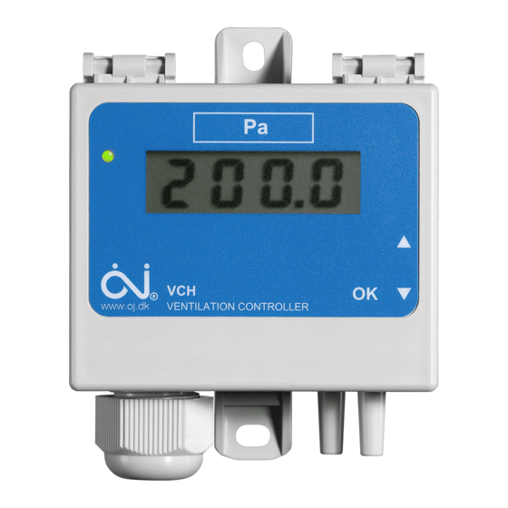
INTRODUCTION
VCH-32x2-DI is electronic pressure/air controller
with integrated regula-tor output, and is
primarily used to control ventilation systems, eg.
roof ventilators using either constant pressure or
constant flow. VCH-32x2-DI is designed for
controlling fans with analog interface.
semiconductor pressure element with no
air throughput, thus protecting the unit from
dust in the ventilation system. The pressure
element is temperature compensated to provide
accurate pressure measurement throughout the
specified temperature range. See 'Technical
Data'.
INSTALLATION
VCH-x2xx-DI should be attached to a firm, level
surface using two screws. The pressure
controller also functions with only one tube fitted
to the tube connectors (+ or -). However, two
tubes should always be fitted to maintain the
enclosure rating.
Pressure is supplied to the measurement unit by
tubes, the higher pressure being connected to
the '+ tube connector' and the lower pressure to
the '÷ tube connector' (see fig. 4).
The pressure tubes must be as short as pos-
sible and must be secured in position to prevent
vibration.
To obtain the best possible results, pressure
must be measured where there is least risk of
turbulence, i.e. in the centre of the ventilation
duct and at a distance of at least twice the width
of the duct from bends and six times the width
from branches (see fig. 3).
The housing is opened without the use of tools
by pressing the snap lock beside the tube con-
nectors.
-DI
Analog cable connection (VCH-3202-DI)
The output from the VCH is either voltage or
current controlled. The VCH must be provided
with a 24 VAC/DC power supply, see figure 4.
Setup menu
Use the buttons
the menu. The buttons can be found on the
• English
backside off the lid. The menu is divided into
three parts - Setup [ Set ], Regulator [ Reg ] and
• Français
Calibration [ CAL ]. Follow the menu scheme in
figure 1 from the bottom up. Note some settings
may be hidden depending on other selections.
Setup - Pressure or flow mode
Use Setup menu 1 to choose between Pressure
or Flow mode.
Setup - Pressure range
Use Setup menu 2 to enter the pressure range.
Set the Pressure range to match the system
pressure working range.
Setup - Pressure setpoint
Use Setup menu 3 to enter the pressure set-
point.
Versions with several setpoints: Choose the
number of setpoints and setup the values for
each one.
Minimum is 0 Pa and maximum is 2500 Pa.
Setting the minimum setpoint to 0 will halt the
ventilation.
The setpoint has to be lower than the Pressure
range.
Setup - k-factor
Use Setup menu 4 to enter the K-factor. Mini-
mum k-factor is 0.001 and maximum k-factor is
9999. Please see the conversion table on page
7 for help to calculate the k-factor. The dot
position shall be set before entering the value.
Setup - Flow range
Use Setup menu 5 to enter the flow range. Set
the Flow range to match the system flow work-
ing range. The dot position shall be set before
entering the value. The selected dot position
will also apply to the display, when showing the
current flow.
Setup - Flow setpoint
Use Setup menu 6 to enter the air flow setpoint.
Versions with several setpoints: Choose the
number of setpoints and setup the values for
each one.
The scale is 0.000 to 9999. Setting the setpoint
to 0 will halt the ventilation.
The setpoint has to be lower than the Pressure
range.
,
and OK to navigate
[
[
[
[
[
[
© 2019 OJ Electronics A/S
Setup - Damping
Use Setup menu 7 to enter the damping.
Minimum damping is 1 seconds and maximum
damping is 30 seconds. A low damping can
result in unsteady readings, while a higher
damping gives a more steady reading but also a
slower response time for the regulation.
Setup - Analog output type
Use Setup menu 8 to enter the analog output
mode. It is possible to switch between 0 - 10
VDC, 0 - 20 mA, 2 - 10 VDC and 4 - 20 mA as
regulator output.
Regulator menu
]
The VCH-x2xx-DI default PI values will fit most
systems. Only change the values if it is required
or for optimization needs.
]
Regulator - Integrator time
Use Regulator menu 1 to set the integrator time.
Minimum integrator time is 1 second and maxi-
mum integrator time is 9999 seconds. A low
value can make the system unstable and a high
]
value can give a slow regulator response.
Regulator - Proportional band
Use Regulator menu 2 to set the proportional
band. Minimum proportional band is 10% and
maximum proportional band is 1000% of the
Pressure/Flow range. A low value can make the
system unstable and a high value can give a
slow regulator response.
Regulator - Dead band
Use Regulator menu 3 to set the dead band.
]
Minimum dead band is 1% and maximum dead
band is 50% of the Pressure/Flow setpoint
[
/
]. If the regulator is used to control
a damper, choose a higher value to avoid exec-
sive activity.
Regulator - Minimum regulator output
]
Use Regulator menu 4 to set the minimum
regulator output. Minimum regulator output can
be set between 0% and 50%.
Regulator - Maximum regulator output
Use Regulator menu 5 to set the maximum
regulator output. Maximum regulator output can
be set between 50% and 100%.
]
Calibration menu
When calibrating, make sure the VCH are in a
pressure free environment. To obtain a pressure
free enviroment remove the two air tubes on the
VCH. For caution reasons, each calibration will
only calibrate ±5 Pa.
Calibration
Use Calibration menu 1 to calibrate. Confirm by
pressing [
].
Factory reset
Use Calibration menu 2 to set the VCH back to
factory reset. Confirm by pressing [
LED INDICATOR
Front
A LED on the frontside of the VCH indicates
the operating status. A constant red lit means
the operating range is not reached. Contrary a
constant green lit means the operating range is
reached. A flashing red lit means that an error is
active. See Troubleshooting for more informa-
tion.
[
]
[
]
[
]
[
]
[
]
[
]
[
]
[
]
[
]
].
1
Advertisement

Subscribe to Our Youtube Channel
Related Manuals for OJ Electronics VCH-3202-DI


Summary of Contents for OJ Electronics VCH-3202-DI
- Page 1 I N S T R U C T I O N S VCH- 67536F 11/19 - (PBV) Analog cable connection (VCH-3202-DI) Setup - Damping The output from the VCH is either voltage or Use Setup menu 7 to enter the damping.
- Page 2 Tel. +45 73 12 13 14 • Fax +45 73 12 13 13 oj@ojelectronics.com • www.ojelectronics.com CE MARKING Regulations OJ Electronics A/S herewith declares that the product is in conformity with the following direc- tives of the European parliament: LVD - Low Voltage Directive...
- Page 3 Utilisez le menu 8 du réglage pour saisir le mode de sortie analogique. Il est possible de basculer entre 0 - 10 VCC, 0 - 20 mA, 2 - 10 VCC et 4 - 20 mA pour la sortie du régulateur. © 2019 OJ Electronics A/S...
- Page 4 * Remarque : VM signifie Valeur mesurée HOMOLOGATION CE Réglementation ** Remarque : La température ambiante influe OJ Electronics A/S déclare par la présente que sur le contraste et la vitesse d’affichage de le produit est conforme aux directives suivantes l’écran LCD du Parlement européen :...
- Page 5 K-Factor [0.001 - 9999] First set the dot possition, then set the value Pressure setpoint [0000 - 2500 Pa] Pressure range [0000 - 2500 Pa] Pressure / Flow mode START [ ] Pressure Pa; [ © 2019 OJ Electronics A/S...
- Page 6 * value (k-factor to enter into VCH- -DI) /h x 1000 l/s x 1000 0.278 1000 0.589 0.0036 0.001 0.001 2.119 0.001 0.278 0.278 588.6 3600 1000 1000 2119 3600 1000 2119 1.699 0.472 1699 471.9 k-Factor conversion table BR1032A011a © 2019 OJ Electronics A/S...
- Page 7 OJ ELECTRONICS A/S Stenager 13B • DK-6400 Sønderborg Tel.: +45 73 12 13 • 14 Fax: +45 73 12 13 13 oj@ojelectronics.com • www.ojelectronics.com The trademark is registered and belongs to OJ Electronics A/S · © 2019 OJ Electronics A/S...
Need help?
Do you have a question about the VCH-3202-DI and is the answer not in the manual?
Questions and answers