
Subscribe to Our Youtube Channel
Related Manuals for OJ Electronics OJ-DV Series


Summary of Contents for OJ Electronics OJ-DV Series
- Page 1 INSTRUCTIONS OJ-DV OJ Drives ® A DRIVES PROGRAMME DEDICATED TO VENTILATION SOLUTIONS...
-
Page 2: Table Of Contents
Technical specifications ............28 © 2016 OJ Electronics A/S... -
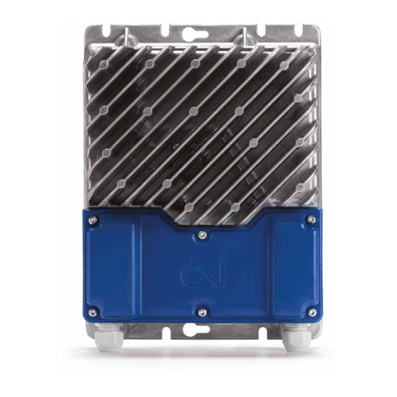
Page 3: Product Presentation
Before connecting mains voltage to OJ-DV, all OJ-DV, motor and fan components must be properly fitted. 4.10. Before connecting mains voltage to OJ-DV, all openings, covers and cable glands must be properly fitted and closed. Unused cable glands must be replaced with blank glands. © 2016 OJ Electronics A/S... -
Page 4: Product Use
• OJ-DV has built-in EMC filter. Approvals and certifications CE marking • OJ Electronics A/S hereby declares under sole responsibility that the product complies with the following European Parliament directives: • LVD - Low voltage: 2006/95/EU • EMC - Electromagnetic compatibility: 2004/108/EU •... -
Page 5: Product Programme
3 x 400 V 244 x 399 x 144 mm All 3x400V versions can also be connected to 3x230V. The power output (kW) will, however, be limited to max. 58% (1/√3) of the rated power output at 3x400V. © 2016 OJ Electronics A/S... -
Page 6: Rating Plate
Table 10.4 numbers and letters, each of which provides Manufacturer's initials information about the specific product, see fig. 10.4 and table 10.4. Product type Electrical connection Controller power/size Optional module type Cable entry Integrated cooling fan © 2016 OJ Electronics A/S... -
Page 7: Exploded And Dimensioned Drawings
3-point stain relief for Modbus connector cable (ribbon cable) Connector for optional modules Power terminals (H1=L, N, PE); (H3, H4, H5=L1, L2, L3, PE) Terminal strip for Modbus and A/D control signals Connector for the earth (PE) protective conductor © 2016 OJ Electronics A/S... - Page 8 Installation Dimensioned drawings Figure 11.2 Figure 11.3 40.5 52.25 40.5 52.25 52.25 40.5 52.25 40.5 Figure 11.4 Figure 11.5 66.5 29.5 54.5 20.7 34.5 107.5 21.5 68.5 55.2 Figure 11.6 40.5 52.25 40.5 52.25 184.5 © 2016 OJ Electronics A/S...
-
Page 9: Mechanical Installation
• To avoid unnecessarily long motor cables (max. 5 m), OJ-DV should be installed as close to the motor as possible. • Use only the pre-cut installation holes/screw holes to secure OJ-DV in place. • Dimensioned drawings, see figs 11.2 to 11.6. Figure 12.4 Figure 12.5 © 2016 OJ Electronics A/S... -
Page 10: Electrical Installation
• Protective earthing of the OJ-DV in combination with the use of RCDs must always be performed in accordance with the relevant local and international requirements, laws and regulations • Failure to follow these precautions can lead to severe or fatal injuries to persons and animals. © 2016 OJ Electronics A/S... -
Page 11: Potential Equalisation
• A 6-core, unshielded, 30 AWG/0.066 mm² telecommunications cable can be used as a Modbus cable. • Generally, cable types with copper conductors are recommended. • For recommended cable dimensions, see table 13.7. © 2016 OJ Electronics A/S... -
Page 12: Opening The Oj-Dv
See fig. 13.9. • The rubber seal has a cut insertion slit and assure the product enclosure rating if properly fitted. See fig. 13.9. • The Modbus cable entry features 3-point strain relief, which must be used. © 2016 OJ Electronics A/S... -
Page 13: 13.10 Spring Terminals
• IMPORTANT! The motor cable must always be a shielded cable and the shield must be ended in the clamp intended for that purpose. See fig. 13.12. • Remember to re-tighten the cable glands to ensure ingress protection and strain relief. © 2016 OJ Electronics A/S... -
Page 14: Mains Voltage Connection
Modbus pins in the RJ12 connectors marked ”A” and ”B”. • The three 3 RJ12 connectors are marked ”A”, ”B” and ”C”. • ”A”: Modbus connection, slave, +24 V voltage in connector. © 2016 OJ Electronics A/S... -
Page 15: 13.15 A/D Control Signal Connections
Bus A +24 VDC and +10 VDC Bus B • Tolerance ± 3% +10Vdc 0-10V In • 0-10V In = Analogue 0-10V control input for Din2 speed Din1 • Potentiometer, electrical connection, see fig. Dout1 13.15.2. © 2016 OJ Electronics A/S... -
Page 16: 13.16 Closing Of Oj-Dv
6 TX20 screws are sufficiently tightened to the tightening torque. At the same time, it must be ensured that the tightening torque is not so high that the blue plastic cover is deformed. © 2016 OJ Electronics A/S... -
Page 17: Checklist - Mechanical And Electrical Installation
Check that all earth connections in the motor and OJ-DV are correctly connected and free of oxidation. Check by means of continuity measurement that the earth connection is active and that the contact resistance complies with applicable local and international directives and regulations. © 2016 OJ Electronics A/S... -
Page 18: Hand Terminal (Hterm) - Connection And Functions
• Various optional modules can be connected to OJ-DV, providing extra versatility where the unit is to be built into systems and applications that require additional inputs and outputs. For further information on the possibilities offered by optional modules, contact OJ Electronics A/S. © 2016 OJ Electronics A/S... -
Page 19: Functions
• The ”+10Vdc”, ”0-10V In” and ”GND” terminals can be connected to a potentiometer, see electrical connection in fig.13.15.2. The function of the digital inputs and outputs has been defined by OJ Electronics A/S as follows: • Din1 = Start/Stop (1 = Start) •... -
Page 20: Braking Power
18.6. With the OJ-DV in frequency converter mode, it is the installer’s responsibility to enter the correct control and motor parameters. © 2016 OJ Electronics A/S... -
Page 21: Electronically Commutated Mode (Ec Mode) - For Pm And Bldc Motors
The controller has to be able to handle this back EMF and that is why you cannot control a PM-SM/ BLDC motor with an OJ-DV controller in frequency converter mode. © 2016 OJ Electronics A/S... -
Page 22: Built-In Protection
• The built-in alarm monitor stops the OJ-DV. • If the alarm situation passes, the alarm is automatically reset and OJ-DV restarted. • If the maximum number of restarts (5 times/60 min) is exceeded, the alarm must be reset manually. © 2016 OJ Electronics A/S... - Page 23 External 24VDC supply overloaded. ✓ Overloading or short circuit on +24V ”NC” ”RP” voltage supply. Abbreviations: ”C”=Critical alarm ”NC”=Non-critical alarm ”RP”=Reduced performance ”SA5”=Motor stops after 5 restarts caused by same fault within 60 min ”S”=Motor stops immediately © 2016 OJ Electronics A/S...
-
Page 24: Modbus Addressing Of Oj-Dv
• Via OJ-DV PCTool, where OJ-DV can be set to other Modbus addresses – see instructions for OJ- DV PCTool. Modbus protocol • Contact OJ Electronics A/S if you require a complete Modbus protocol. Maintenance 22.1. OJ-DV is maintenance free under normal operating conditions and load profiles. -
Page 25: Troubleshooting
0 = Auto 1 = Low = 4 kHz 2 = High = 8 kHz Increasing switching frequency increases losses within OJ-DV, thus reducing efficiency. OJ-DV switching frequency can be changed via OJ-DV Hterm or via Modbus. © 2016 OJ Electronics A/S... - Page 26 OJ-DV and reconnecting it after approx. 60 seconds. The alarm is re-activated after reset Read out the alarm via Modbus registers and determine which alarm has stopped the controller/motor. Remedy the cause of repeated alarm activation. © 2016 OJ Electronics A/S...
-
Page 27: Disposal
• OJ-DV contains electronic components and must not be disposed of together with household waste. • OJ-DV must be disposed of in accordance with applicable local rules and regulations. • OJ-DV meets the requirements on marking of electronic waste contained in the European WEEE Directive 2012/19/EU. © 2016 OJ Electronics A/S... -
Page 28: Technical Specifications
OJ Electronics A/S Stenager 13B • DK-6400 Sønderborg Tel. : +45 73 12 13 14 • Fax +45 73 12 13 13 oj@ojelectronics.com • www.ojelectronics.com The trademark is a registered trademark belonging to OJ Electronics A/S · © 2016 OJ Electronics A/S...
Need help?
Do you have a question about the OJ-DV Series and is the answer not in the manual?
Questions and answers