SOLIS S6-EH1P3.8K-H-US User Manual
High voltage hybrid single phase residential energy storage inverter
Hide thumbs
Also See for S6-EH1P3.8K-H-US:
- User manual (94 pages) ,
- Product manual (59 pages) ,
- User manual (74 pages)

Related Manuals for SOLIS S6-EH1P3.8K-H-US


Summary of Contents for SOLIS S6-EH1P3.8K-H-US
- Page 1 User Manual High Voltage Hybrid Single Phase Residential Energy Storage Inverter Applicable Models: S6-EH1P3.8K-H-US S6-EH1P5K-H-US S6-EH1P7.6K-H-US S6-EH1P10K-H-US S6-EH1P11.4K-H-US Version 4.1 Release Date: 09/12/2023...
- Page 2 ● Airborne noise produced depending on the environment. ● Potential flammability hazards. ● Solis will not be held liable for defects or malfunctions arising from: ● Improper use of the equipment. ● Deterioration resulting from transportation or particular environmental conditions.
- Page 3 Table of Contents Introduction Safety Overview Installation Commissioning Troubleshooting Specifications Appendix...
-
Page 4: Table Of Contents
Table of Contents 1. Introduction...................... 1.1 Inverter Description..................1.2 Included Components ................. 1.3 Tools Required for Installation ..............1.4 Inverter Storage ..................2. Safety & Warning........................2.1 Safety ......................2.2 General Safety Instructions ................. 2.3 Notice for Use..................... 2.4 Notice for Disposal ..................2.5 Protection Circuitry and Controls.............. -
Page 5: Introduction
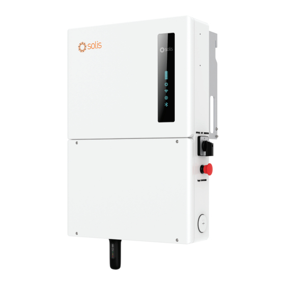
1. Introduction 1.1 Inverter Description The Solis S6 Hybrid series is designed for residential applications. The inverter can work with high-voltage lithium ion batteries to maximize self-consumption and provide backup power if the grid fails and there is not enough PV power to cover load demand. - Page 6 1. Introduction Mounting Bracket Hook Carrying Handle DC Disconnect Switch 1 in. Knockout for DC PV Solis Data Logger (sold separately) Figure 1.3 Right Side View Mounting Bracket Hook Carrying Handle AC Bypass Switch Rapid Shutdown Initiation Switch 1 ½ in. Knockout for AC Grid Solis Data Logger (sold separately) Figure 1.4 Left Side View...
- Page 7 1. Introduction Heat Sink for Convective Cooling 1 ½ in. Knockout for AC Grid or Backup 1 in. Knockout for DC Battery or PV Figure 1.3 Back View Figure 1.4 Top View...
-
Page 8: Included Components
1. Introduction 1.2 Components Included with the Inverter If any of these items are missing, please contact your local Solis distributor or the Solis service team. Inverter Mounting Bracket x1 Stabilizing Set Screws x2 Inverter x1 1/2 inch Cable Glands x2... -
Page 9: Inverter Storage
1. Introduction 1.4 Inverter Storage ● If the inverter is not installed immediately, please abide by the storage instructions and environmental conditions listed below. ● Use the original box to repackage the inverter, seal with adhesive tape with the desiccant inside the box. -
Page 10: Safety & Warning
2. Safety & Warning 2.1 Safety The following types of safety instructions and general information appear in this document as described below: DANGER “Danger” indicates a hazardous situation which if not avoided, will result in death or serious injury. WARNING “Warning”... - Page 11 NEC Article 690, Part II. All Solis single phase inverters feature an integrated DC disconnect switch. CAUTION Risk of electric shock, do not remove the cover. There are no serviceable parts inside, refer servicing to qualified and accredited service technicians.
-
Page 12: Notice For Use
Local waste management rules shall be observed and respected. 2.5 Protection Circuitry and Controls To meet relevant codes and standards, the Solis U.S. single phase inverter line is equipped with protective circuitry and controls. These include Arc Fault Circuit Interrupter (AFCI) and Anti-Islanding Protection. -
Page 13: Overview
3. Overview 3.1 LED Indicator Lights There are five indicator lights on the the Solis S6-EH1P(3.8-11.4)K-H-US Series Inverter: Battery, Inverter, Wi-Fi, RS485 and Bluetooth. These lights indicate the working status of the inverter. The inverter creates a Bluetooth signal which is what the smart phone connects to so that the inverter interface page can be accessed. -
Page 14: Inverter Wire Box And Connection Points
Conduit and PV conductors should be connected here 2. PV Conduit for battery conductors should be connected here 3. Battery Solis USB data loggers are to be connected here 4. Solis Logger Port Conduit for AC conductors to backup loads panel should be connected here 5. AC-Backup Conduit for AC conductors to the main service panel should be connected here 6. -
Page 15: Operating Modes
Figure 4.4 Solis S6 hybrid with export power control enabled Each Solis S6 hybrid comes with an energy meter, which gets installed externally to the inverter. The energy meter uses two CTs, which measure the power being consumed by the home. The hybrid uses the data from this meter to determine whether or not it needs to curtail the PV power to meet the export power limitation. -
Page 16: Energy Storage
Battery S6 Hybrid Figure 4.4 Backup power with Solis S6 hybrid If the primary purpose of the energy storage system is to store as much of the PV power as possible so that it can be used later to offset the usage of grid power, this is known as energy arbitrage. - Page 17 No Grid Battery S6 Hybrid Figure 4.4 Off-grid power with Solis S6 hybrid 4.2.2 Backup Power This inverter is capable of providing AC power to home loads using PV and battery power in the event of a grid failure. When the inverter senses that the grid power has been lost, it automatically opens the relay connecting itself to the grid.
- Page 18 4. Installation The homeowner will need to be consulted to understand why they are installing a battery. It should also be determined how much power is consumed, how much power the PV will generate, how much storage power there will be, and which loads are to be backed up in the event of a power outage (grid failure).
- Page 19 PV production is temporarily suspended as to not backfeed the generator. The inverter will use generator power to supply loads and recharge the battery. Battery Generator S6 Hybrid Off-Grid Home (recommended) Table 4.4 AC-coupled Solis S6 hybrid system...
- Page 20 4. Installation 4.2.5 AC-Coupling The Solis S6 hybrid can be AC-coupled or DC-coupled to a home. AC-coupled means that the energy storage is connected to the AC-side of the system. Typically, the battery and inverter pair are connected in parallel with an existing PV system. The battery will charge with PV power that gets converted from DC, to AC, and then back to DC again.
- Page 21 The frequency derating (droop) curve is based on the IEEE 1547-2018 standard. The AC-coupled PV system must also support frequency-watt shifting based on IEEE 1547-2018. If the AC-coupled PV system cannot or does not support this function, then the system will shut off as the Solis S6 hybrid shifts the frequency.
- Page 22 DC power from the PV. Typically, DC-coupling is done when additional PV is being added or when the system is new and being installed with energy storage. Table 4.5 DC-coupled Solis S6 hybrid system Whole-home and partial-home back up can be achieved with DC Coupling. Depending on the battery model, the S6 hybrid can connect with between 10 and 150kWh of stored power to provide in backup mode or for energy arbitrage.
- Page 23 The S6 hybrid inverter could be used to retrofit an older PV system with energy storage. The old PV inverter would need to first be removed. The Solis S6 hybrid would then be installed in place of the old inverter. The PV would connect to the S6 inverter directly, provided the specifications of the PV strings are within the tolerance ranges of the Solis S6 hybrid inverter.
-
Page 24: Installation
5. Installation 5.1 Select a Location to Install the Inverter When selecting a location for the inverter, the following criteria should be considered: Exposure to direct sunlight may cause output power derating due to overheating It is recommended to avoid installing the inverter in direct sunlight. The ideal location is one where the ambient temperature does not exceed 40°C (140°F) It is also recommended to install the inverter somewhere the rain and snow will not land directly on it. - Page 25 ● Consult the technical specifications sections at the end of this manual for additional environmental condition requirements (temperature range, altitude, etc.) 5.1.3 Angle of installation ● This model of Solis inverter must be mounted vertically (90° degrees not greater or less than 90° degrees straight up).
-
Page 26: Product Handling
5. Installation 5.1.4 Avoiding direct sunlight Installation of the inverter in a location exposed to direct sunlight should to be avoided. Direct exposure to sunlight could cause: ● Power output limitation (with a resulting decreased energy production by the system). ●... -
Page 27: Mounting The Inverter
4. Installation 5.3 Mounting the Inverter Mount the inverter on a wall or structure capable of bearing the weight of the machine The inverter must be mounted upright on a vertical structure with a tilt of 90°. A tilt greater or less than 90°... - Page 28 5. Installation 5.3 Mounting the Inverter Length Width Depth 34 ¹⁄₁₆ in. (866 mm) 19 ¹⁄₁₆ in. 5 ⅜ in. (485 mm) (136.5 mm) 21 ⅞ in. 8 ⅝ in. (555.5mm) (218.5 mm) Figure 4.6 Inverter Dimensions Figure 4.7 Inverter Bracket Dimensions Once a suitable location has been found according to 4.2 and 4.3, use figures 4.6 and 4.7 to mount the bracket to the wall.
- Page 29 5. Installation NOTE: The inverter must be mounted vertically at a 90° angle. Four fasteners must be used to ensure the bracket does not come off the wall. At least two must embed in a wall stud to bear the inverter weight. Bracket Fasteners Figure 4.8 Fix the bracket to the wall...
-
Page 30: Inverter Wiring Overview
(For more details, please refer to the on SolisCloud (Optional) Solis data logger product manual) Table 4.1 System Cable Connections Conductor, conduit, and overcurrent protection device sizing shall be done in accordance with the NEC and local electrical codes & standards. -
Page 31: External Grounding
5. Installation 5.5 External Grounding An optional external ground connection point is available on the right side of inverter. The internal ground bar is grounded to the inverter chassis. Figure 4.10 External Grounding Conductor Terminal Location To connect the grounding terminal on the heat sink, please follow the steps below: 1. -
Page 32: Pv Cable Installation
5. Installation 5.6 PV Cable Installation DANGER: Before installing the PV cables, be sure that the PV array is disconnected. Use a multimeter to verify that the PV string voltages are 0V before proceeding. If rapid shutdown is being used, then under 30Vdc per string is safe. Please verify the following before connecting the PV strings to the inverter: Ensure the DC voltage of the PV strings will not exceed the maximum DC input voltage (600Vdc). -
Page 33: Rapid Shutdown
5. Installation 5.7 Rapid Shutdown 5.7.1 Integrated Rapid Shutdown Important Note The inverter comes (optional) with an internal rapid shutdown transmitter. This transmitter brand must match the receivers that are being installed with the PV modules. Not abiding by this will void the inverter warranty. How the inverter achieves module-level rapid shutdown: The internal transmitter generates a PLC signal when it receives AC power. - Page 34 Please see the Compatibility Sheet for details on which internal transmitter options are currently available for the Solis S6 hybrid inverter. 5.7.2 External Rapid Shutdown If the inverter is being installed where it is inaccessible to first responders, an external rapid shutdown switch must be installed somewhere it is accessible.
-
Page 35: Battery Cable Installation
Compatibility sheet for specifics on which battery models this inverter will support. NOTE: The battery fuse in the inverter wire box is replaceable. The replacement can only be done by a technician authorized by Solis. Fuse specification: 750V, 63A. NOTE:... -
Page 36: Ac Wiring
Table 4.4: Grid Max Output Backup Rated Backup Max Output Grid Max Input Inverter Model Current Output Current Current (10 sec) Current S6-EH1P3.8K-H-US 15.8A 23.8 23.8A 15.8A 25.4A S6-EH1P5K-H-US 20.8A 31.2A 20.8 33.3A... - Page 37 4. Installation 5.9.2 Installing the AC cables WARNING: Conductors terminated in the backup ports of the inverter must be connected to an isolated load center that is not directly connected to the utility. This ensures that the system complies with anti-islanding requirements. Steps for installing the AC grid and backup conductors 1.
- Page 38 4. Installation 5.9.4 AC Bypass Switch This failsafe switch determines the power source for the inverter backup circuit. If the inverter fails or has a critical alarm, the backup circuit will shut off. Should this occur, the switch set to 1 allows power to pass through the inverter to the backup from the grid. The switch settings operate as follows: BYPASS (1) the backup circuit is powered by the grid directly.
- Page 39 95A (47.5A x 2) of continuous backup power with up to 152A of surge current for ten seconds. SolisHub Solis also makes a microgrid interconnect device (MID), called the SolisHub. The SolisHub allows for a streamlined whole-home backup solution that provides load shedding control and 200A of pass-through power.
- Page 40 2. Connect a 2-conductor cable to from the generator dry-contact to the inverter pins Dry_con_A and Dry_con_B on the inverter communication terminal block. 3. See pages X through X for steps on how to commission the system with a generator. Solis S6 Hybrid Dry Contact B Inverter AC Terminals...
- Page 41 Main Breaker Figure 4.19 Backup with an AC-Coupled PV System There is no direct communication between the Solis S6 hybrid and the AC-coupled PV system. The inverter uses frequency-shifting to modulate the output of the ACPV system. The inverter uses the frequency-watt curve outlined in the IEEE 1547-2018 standard.
-
Page 42: Inverter Communication
5. Installation 5.10 Inverter Communication 5.10.1 Communication Terminals Overview 9 10 11 12 13 14 15 16 Figure 4.19 Inverter communication terminals The inverter communication terminal block consists of 16 ports. From left to right, the chart below explains what purpose of each port is. Acceptable Port Function... - Page 43 Grid U lity Meter Main Service Panel Solis S6 Hybrid Main Breaker Meter Power Supply & Grid Voltage Reference Breaker Figure 4.20 Acrel Meter Wiring Diagram (Acrel AGF-AE-D) The Acrel meter must be installed in order to have a fully-functioning system. If the meter is not installed, key functions such as export power control and default energy storage modes will not be available.
- Page 44 CAN-H (blue wire) CAN-L (blue-white wire) Battery CAN Port RJ 45 Connector RJ 45 Pin Layout Solis S6 Hybrid Figure 4.21 Battery CAN Communication RS485 LG RESU Prime Battery Solis S6 Hybrid Figure 4.22 Battery RS 485 Communication Note: Some alarm codes are being relayed from the battery.
- Page 45 5. Installation 5.10.4 Parallel Inverter Communication There are two RJ45 ports reserved for communication between Solis S6 hybrids only. The communication is CAN and is the ports are not able to be used for any other purpose besides daisy-chaining Solis S6 hybrids together.
- Page 46 Figure 4.14 External emergency power off switch 5.10.6 Inverter Bluetooth Network The Solis S6 hybrid generates a Bluetooth network which allows technicians to directly interface with the inverter using a smart phone or tablet. The accessory kit will include a Bluetooth antenna. Remove the black protective cap from the “Antenna” port on the bottom of the inverter.
-
Page 47: Commissioning
6. Commissioning 6.1 Pre-Commissioning Steps Visually inspect each piece of equipment in the system closely. Check all conduit and cable connection points to ensure they are tight. Verify that all system components have adequate space for ventilation. Follow each cable to ensure that they are all terminated in the proper places. E nsure that all warning signs and labels are affixed on the system equipment. - Page 48 6. Commissioning Step 4: Turn your phone Bluetooth on and then open the SolisCloud app. Tap “Service”, then tap “Local Operation”, and then tap ”Connect with Bluetooth”. The name of the inverter Bluetooth network will display as “INV_” and then the inverter serial number.
- Page 49 6. Commissioning Tap the toggle switch for Follow Phone Time to match the inverter time to your phone time or manually set the time yourself, then tap Next Step. Select the battery that is installed, and if no battery is installed, then tap No Battery.Tap Next step, and then verify that Acrel 1P Meter is selected.
- Page 50 6. Commissioning The Work Mode is the energy storage operating mode of the inverter. Please see the logic tables on pages XX through XX for explanations on how the modes operate to determine which one you should select for each system. Upon selecting the mode, you will need to toggle the on switch for that mode.
- Page 51 6. Commissioning The Peak-shaving Mode has additional settings for Max. useable Grid Power and Peak SOC. Max. useable Grid Power is the most amount of power that the inverter can import from the grid to cover load demand. The Peak SOC is the target state-of-charge percentage that the system will try to reach by the time the peak window starts.
- Page 52 Step 8: If there is an existing PV system being AC-coupled to the Solis S6, please follow this next step, and if not then skip this step. Tap AC Coupling in the main Setting menu.
- Page 53 6. Commissioning Next, tap GEN Power Setting and then input the GEN Rated Power and Gen. Max. Charge Power values. These can be determined from the generator specification label. After that, change the Generator Position from GEN port to Grid port. Next, for the Grid Port Powered By setting, this should be set to Generator only for off-grid systems.
- Page 54 6. Commissioning Step 10: If there are multiple Solis S6 hybrid inverters connected in parallel, please follow this step. If there is only one hybrid in the system, this step can be skipped. Tap Parallel Setting and then tap Parallel Mode. Change this from Single to Parallel, then tap Save.
- Page 55 The next section goes over troubleshooting and you can always contact Solis USA technical support with any questions or concerns. The inverter commissioning process has now been completed.
-
Page 56: Troubleshooting
If you are not able to resolve the alarm code using the troubleshooting steps, or if the alarm code you are seeing is not listed, please contact Solis US Technical support. Use the Bluetooth tool, go to the Info page and then to the Inverter tab. Scroll down and tap Alarm History and then screen shot or write down the alarms as well as the dates and times the alarms were recorded. - Page 57 7. Troubleshooting Alarm Message Failure description Solution 1. Check if there is an arc in the PV ARC-FAULT ARC detected in DC circuit connection and restart inverter. AFCI Check FAULT AFCI module self check fault 1. Restart inverter or contact installer. DCinj-FAULT High DC injection current 1.
- Page 58 7. Troubleshooting Alarm Message Failure description Solution Over DC voltage OV-DC01/02/03/04 1. Reduce the module number in series. 1. Restart inverter. 2. Identify and remove the string of the DC input overcurrent OV-DCA-I faulted MPPT. 3. Change power board. 1. Resistance of AC Cable is too high. Increase the gauge of grid cables.
- Page 59 Solis after-sales service +1(866)438-8408 or email usservice@solisinverters.com If you have any technical problems with the hybrid system, please contact Solis after-sales service. We recommend gathering the following information before making contact in order to get a quicker resolution.
-
Page 60: Specifications
8. Specifications Technical Data S6-EH1P3.8K-H-US S6-EH1P5K-H-US Input DC (PV side) Recommended max. PV power 6,080W 8,000W Max. input voltage 600V Rated voltage 380V Start-up voltage MPPT voltage range 80-550V Full load MPPT voltage range 140-450V Max. input current per string Max. - Page 61 8. Specifications Technical Data S6-EH1P3.8K-H-US S6-EH1P5K-H-US AC Output (Backup and Off-grid) Rated output power 3.8kW Max. apparent output power 6.1 kVA, 10 sec 8 kVA, 10 sec Back-up switch time <10 ms Phase Power 240V Split-Phase Rated output voltage(L1-L2)/(L1/L2-N) 240 V/120 V...
- Page 62 8. Specifications Technical Data S6-EH1P3.8K-H-US S6-EH1P5K-H-US General data Dimensions(H/W/D) 19.21*28.35*8.66 in (647*488*228.5 mm) Weight 59.52 Ibs (27 kg) Topology Transformerless Operation temperature range -25~+60 ℃/-31~+140 ℉ Ingress protection NEMA 4X(IP66) <30 dB (A) Noise emission (Typical) Cooling method Natural convection Max.
- Page 63 8. Specifications Technical Data S6-EH1P7.6K-H-US S6-EH1P8K-H-US Input DC (PV side) Recommended max. PV power 12160W 12800W Max. input voltage 600V Rated voltage 380V Start-up voltage MPPT voltage range 80-550V Full load MPPT voltage range 175-450V 185-450V Max. input current per string Max.
- Page 64 8. Specifications Technical Data S6-EH1P7.6K-H-L-US S6-EH1P8K-H-US AC Output (Backup and Off-grid) Rated output power 7.6kW Max. apparent output power 12.2 kVA, 10 sec 12.8 kVA, 10 sec Back-up switch time <10 ms Phase Power 240V Split-Phase Rated output voltage(L1-L2)/(L1/L2-N) 240 V/120 V AC output voltage range 204-276 V Rated grid frequency...
- Page 65 8. Specifications Technical Data S6-EH1P7.6K-H-L-US S6-EH1P8K-H-US General data Dimensions(H/W/D) 22.1*29.53*8.6 in (650*750*238.200mm) Weight 71.74 Ibs (32.5 kg) Topology Transformerless Operation temperature range -25~+60 ℃/-31~+140 ℉ Ingress protection NEMA 4X(IP66) <30 dB (A) Noise emission (Typical) Cooling method Natural convection Max. operating altitude 13,120 ft (4000 m) UL1741 SB, UL1741 SA, IEEE1547.1-2020, UL1699B, UL1998, FCC Part 15 Class B, California Rule 21, HECO Rule 14H (pending),...
- Page 66 8. Specifications Technical Data S6-EH1P10K-H-US S6-EH1P11.4K-H-US Input DC (PV side) Recommended max. PV power 16,000W 18,240W Max. input voltage 600V Rated voltage 380V Start-up voltage MPPT voltage range 80-550V Full load MPPT voltage range 230-450V 245-450V Max. input current per string Max.
- Page 67 8. Specifications Technical Data S6-EH1P10K-H-US S6-EH1P11.4K-H-US AC Output (Backup and Off-grid) Rated output power 10kW 11.4kW Max. apparent output power 16 kVA, 10 sec 18.2 kVA, 10 sec Back-up switch time <10 ms Phase Power 240V Split-Phase Rated AC output voltage 240 V/120 V AC output voltage range 204-276 V...
- Page 68 8. Specifications Technical Data S6-EH1P10K-H-US S6-EH1P11.4K-H-US General data Dimensions(H/W/D) 22.1*29.5*8.6 in (560*750*200 mm) Weight 71.74 Ibs (32.5 kg) Topology Transformerless Operation temperature range -25~+60 ℃/-31~+140 ℉ Ingress protection NEMA 4X (Ip66) <30 dB (A) Noise emission (Typical) Cooling method Natural convection Max.operation altitude 13,120 ft (4000 m) UL1741 SB, UL1741 SA, IEEE1547.1-2020, UL1699B, UL1998,...
-
Page 69: Appendix
9. Appendix 9.1 Temperature Derating Curve (120.2°F) (131°F) (140°F) 9.2 Inverter Internal Topology Overview... -
Page 70: Ul Certification
MEX, S6-EH1P7.6K-H-L-MEX, S6-EH1P8K-H-MEX, S6-EH1P10K-H-MEX and S6-EH1P11.4K-H-MEX, permanently connected. Bi-directional Transformerless Grid Support Utility Interactive Power Conversion Equipment, S6-EH1P(3.8- 11.4)K-H-US series, include Models S6-EH1P3.8K-H-US, S6-EH1P5K-H-US, S6-EH1P6K-H-US, S6- EH1P7.6K-H-S-US, S6-EH1P7.6K-H-L-US, S6-EH1P8K-H-US, S6-EH1P10K-H-US and S6-EH1P11.4K-H-US, permanently connected. For details related to rating, size, configuration, etc., reference should be made to the CSA Certification Record, Certificate of Compliance, Annex A, or the Descriptive Report. - Page 71 9. Appendix 8.5 UL Certification Certificate: 80127112 Master Contract: 273488 Project: 80127113 Date Issued: 2023-01-13 APPLICABLE REQUIREMENTS CSA-C22.2 No.107.1-16 Power Conversion Equipment *UL Std No. 1741 Inverters, Converters, Controllers and Interconnection System Equipment for Use With Distributed Energy Resources (Third Edition, Dated September 28, 2021) **UL 1699B Photovoltaic (PV) DC Arc-Fault Circuit Protection (First Edition, Revision Dated August 22, 2018)
- Page 72 Description 80127113 2023-01-13 Updated report 80127112 to add S6-EH1P(3.8-11.4)K-H-US series inverter, include models S6-EH1P3.8K-H-US, S6-EH1P5K-H-US, S6-EH1P6K-H- US, S6-EH1P7.6K-H-S-US, S6-EH1P7.6K-H-L-US, S6-EH1P8K-H-US, S6- EH1P10K-H-US, S6-EH1P11.4K-H-US and evaluate the Grid support function to comply with UL 1741 Supplement SA8-SA18 with the SRDs of California Electric Rule 21 and UL 1741 Supplement SB according to IEEE 1547.1-2020 with SRDS IEEE 1547-2018 and IEEE 1547a-2020.
- Page 73 Ginlong Technologies Co., Ltd. No. 57 Jintong Road, Binhai Industrial Park, Xiangshan, Ningbo, Zhejiang, 315712, P.R.China. Tel: +1(866)438-8408 If you encounter any problems with the inverter, please take note of the inverter serial number and then contact us using the phone number or email listed above. Compliant with CA Rule 21 &...
Need help?
Do you have a question about the S6-EH1P3.8K-H-US and is the answer not in the manual?
Questions and answers