SOLIS S6-EH1P5K-H-US User Manual
Home energy storage high voltage hybrid inverter
Hide thumbs
Also See for S6-EH1P5K-H-US:
- User manual (94 pages) ,
- Product manual (59 pages) ,
- User manual (73 pages)

Related Manuals for SOLIS S6-EH1P5K-H-US


Summary of Contents for SOLIS S6-EH1P5K-H-US
- Page 1 User Manual Home Energy Storage High Voltage Hybrid Inverter Applicable Models: S6-EH1P3.8K-H-US S6-EH1P5K-H-US S6-EH1P7.6K-H-US S6-EH1P9.9K-H-US S6-EH1P10K-H-US S6-EH1P11.4K-H-US Version 5.4 Release Date: 07/2024...
- Page 2 ● Airborne noise produced depending on the environment. ● Potential flammability hazards. ● Solis will not be held liable for defects or malfunctions arising from: ● Improper use of the equipment. ● Deterioration resulting from transportation or particular environmental conditions.
- Page 3 Table of Contents Introduction Safety Overview Operating Modes Installation Commissioning Troubleshooting Specifications Appendix...
-
Page 4: Table Of Contents
Table of Contents 1. Introduction....................... 1.1 Inverter Description..................1.2 Included Components ................... 1.3 Tools Required for Installation ............... 1.4 Inverter Storage .................... 2. Safety & Warning........................2.1 Safety ......................2.2 General Safety Instructions ................2.3 Notice for Use....................2.4 Notice for Disposal ..................2.5 Protection Circuitry and Controls.............. - Page 5 Table of Contents 7. Troubleshooting........................7.1 Inverter Shutdown Procedure................. 7.2 Inverter Maintenance..................7.3 Inverter Alarm Codes..................7.4 Inverter Firmware..................8. Specifications........................... 9. Appendix..........................9.1 Temperature Derating Curve................9.2 Inverter Internal Toplogy................9.3 UL 1741 Certification..................9.4 UL 1741 Power Control Systems (PCS) CRD........... 9.5 Default Settings for IEEE1547-2018 (UL-240V-18 Standard)......
-
Page 6: Introduction
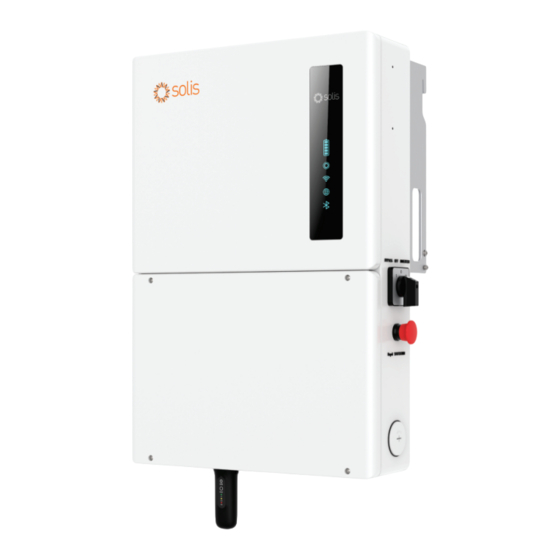
1. Introduction 1.1 Inverter Description The Solis S6 Hybrid series is designed for residential applications. The inverter can work with high-voltage lithium ion batteries to maximize self-consumption and provide backup power if the grid fails and there is not enough PV power to cover load demand. - Page 7 1. Introduction Mounting Bracket Hook Carrying Handle DC Disconnect Switch 1 in. Knockout for DC PV Solis Data Logger Figure 1.3 Right Side View Mounting Bracket Hook Carrying Handle AC Bypass Switch Rapid Shutdown Initiation Switch 1 ½ in. Knockout for AC Grid Solis Data Logger Figure 1.4 Left Side View...
- Page 8 1. Introduction Heat Sink for Convective Cooling 1 ½ in. Knockout for AC Grid or Backup 1 in. Knockout for DC Battery or PV Figure 1.5 Back View Figure 1.6 Top View...
-
Page 9: Included Components
1. Introduction 1.2 Components Included with the Inverter If any of these items are missing, please contact your local Solis distributor or the Solis service team. Mounting Bracket Spare Wire Box Inverter Mounting Bracket x1 Stabilizing Set Screws x4 Lag Bolts x4... -
Page 10: Inverter Storage
1. Introduction 1.4 Inverter Storage ● If the inverter is not installed immediately, please abide by the storage instructions and environmental conditions listed below. ● Use the original box to repackage the inverter, seal with adhesive tape with the desiccant inside the box. -
Page 11: Safety & Warning
2. Safety & Warning 2.1 Safety The following types of safety instructions and general information appear in this document as described below: DANGER “Danger” indicates a hazardous situation which if not avoided, will result in death or serious injury. WARNING “Warning”... - Page 12 NEC Article 690, Part II. All Solis single phase inverters feature an integrated DC disconnect switch. CAUTION Risk of electric shock, do not remove the cover. There are no serviceable parts inside, refer servicing to qualified and accredited service technicians.
-
Page 13: Notice For Use
Local waste management rules shall be observed and respected. 2.5 Protection Circuitry and Controls To meet relevant codes and standards, the Solis U.S. single phase inverter line is equipped with protective circuitry and controls. These include Arc Fault Circuit Interrupter (AFCI) & Anti-Islanding Protection. -
Page 14: Overview
3. Overview 3.1 LED Indicator Lights There are five indicator lights on the the Solis S6-EH1P(3.8-11.4)K-H-US Series Inverter: Battery, Operation, Logger, RS485 and Bluetooth. These lights indicate the operating status of the inverter. The inverter generates a Bluetooth signal. To access the inverter interface, a smart phone must connect through the SolisCloud app. -
Page 15: Inverter Wire Box And Connection Points
Conduit and PV conductors should be connected here 2. PV Conduit for battery conductors should be connected here 3. Battery Port (USB) for connecting Solis data loggers only 4. Solis Logger Port Conduit for AC conductors to backup loads panel should be connected here 5. AC-Backup Conduit for AC conductors to the main service panel should be connected here 6. -
Page 16: Operating Modes
Figure 4.2 Solis S6 hybrid with export power control enabled Each Solis hybrid comes with an energy meter, which gets installed externally to the inverter. The energy meter uses two CTs, which measure the power being consumed and imported by the home. -
Page 17: Energy Storage
Battery S6 Hybrid Figure 4.3 Backup power with Solis S6 hybrid If the primary purpose of the energy storage system is to store as much of the PV power as possible so that it can be used later to offset the consumption of grid power, this is known as energy arbitrage. - Page 18 4. Operating Modes 4.2.2 Energy Arbitrage The S6 hybrid inverter has multiple operating modes which can be programmed so that the performance of the system is tailored to the specific needs of each individual system owner. The backup power function of the inverter can be enabled or disabled independently of the energy arbitrage modes:(1) Self-Use (2) Peak-Shaving (3) Feed-in-Priority Self-Use Mode Self-Use is the default energy storage mode.
- Page 19 4. Operating Modes Feed-In-Priority Mode This mode can be thought of as export priority mode. The system will first supply the home loads with PV power and then it will seek to export the excess PV power, up to the set limit. Once the limit is reached, the remaining power will be stored in the battery.
-
Page 20: Dc Coupling Vs Ac Coupling
DC-coupling methods.. 4.3.2 AC-Coupling The Solis S6 hybrid can be DC-coupled or AC-coupled to a home to add energy storage. In an AC-coupled the energy storage is connected to the AC-side of the system. Typically, the battery and Solis hybrid pairing get connected in parallel with an existing PV system. - Page 21 The maximum output power of the existing PV inverter must be less than the maximum output power of the Solis hybrid inverter. AC coupling can be done on either the grid side or the backup side. However, if it is on the backup side, then the max.output power of the existing PV inverter...
-
Page 22: Partial-Home Vs Whole-Home Backup
4. Operating Modes 4.4 Partial-Home vs Whole-Home Backup This inverter is capable of providing AC power to home loads using PV and battery power in the event of a grid failure. When the inverter senses that the grid power has been lost, it automatically opens the relay between itself and the grid. - Page 23 47.5A on its own, to get a full 200A requires the addition of SolisHub with the inverter. SolisHub is designed to work with the Solis-S6EH1P(3.8-11.4)K-H-US inverter series. The purpose is to provide a seamless whole-home backup solution.
-
Page 24: Backup Power Inverter Paralleling
Battery S6 Hybrid Figure 4.15 Backup with paralleled Solis hybrids It should first be determined what the maximum continuous current needs to be in order to meet the energy demand of the home. Up to three S6 hybrid inverters can be installed in parallel with PV and batteries to provide continuous backup power. - Page 25 190A 237.5A 285A Figure 4.16 Backup power chart based on Solis model and number of paralleled units Backup Combiner Load Center In the diagrams of this manual a Backup Combiner Load Center is often shown that is additional to the Backup Home Load Center. The Combiner is not required, but it does provide additional breaker slots to host multiple inveter breakers if one is installed.
- Page 26 4.5.2 Power Control System (PCS) with SolisHub The Solis S6 hybrid inverter is UL 1741 PCS CRD certified. This means that the inverter is able to regulate the current and limit the loading on the busbars and conductors. The PCS can limit the power flow as to not exceed any busbar rating limits.
- Page 27 4. Operating Modes Solis Power Control System (PCS) Operating Modes 1. Unrestricted Mode: This mode should be used Utility Battery when PCS is not required. The system is permitted to charge the batteries with grid power and can discharge import discharge-export battery power to the grid.
-
Page 28: Generator Operation
Figure 4.18 Off-grid system with a generator and no utility power The Solis hybrid can work with a generator that is also connected to a grid. However, an external ATS must be installed with the generator. This ATS would not be produced by Solis. When the grid is lost the ATS will disconnect from the grid but not start the generator until the inverter sends the start signal using dry contact. -
Page 29: Wiring Diagrams
String-1 String-2 String-3 String-4 +BAT -BAT Backup Load Center 4.7.2 Partial-Home Backup with One Solis Hybrid and an AC-Coupled System represents an AC Disconnect AC Grid U lity L2 - Line 2 Meter L1 - Line 1 Note: AC disconnect switches may be... - Page 30 String-3 String-4 String-4 +BAT +BAT -BAT -BAT Backup Load Center 4.7.4 Whole-Home Backup with Two Solis Hybrid Inverters and SolisHub L2 - Line 2 Grid L1 - Line 1 represents an AC Disconnect U lity N - Neutral Meter Note: AC disconnect switches may be...
- Page 31 4. Operating Modes 4.7.5 Off-Grid System with a Generator and One Solis Hybrid Inverter L2- Line 2 Dry Contact Dry Contact L1- Line 1 N– Neutral N PE PE- Ground Dry Contact A/B/Ground Main Panel Generator Note: AC disconnect switches may be...
-
Page 32: Installation
5. Installation 5.1 Select a Location to Install the Inverter When selecting a location for the inverter, the following criteria should be considered: Exposure to direct sunlight may cause output power derating due to overheating It is recommended to avoid installing the inverter in direct sunlight. The ideal location is one where the ambient temperature does not exceed 40°C (140°F) It is also recommended to install the inverter somewhere the rain and snow will not land directly on it. -
Page 33: Product Handling
5. Installation 5.1.4 Avoiding direct sunlight Installation of the inverter in a location exposed to direct sunlight should to be avoided. Direct exposure to sunlight could cause: ● Power output limitation (with a resulting decreased energy production by the system). ●... - Page 34 Consult the technical specifications sections at the end of this manual for additional environmental condition requirements (temperature range, altitude, etc.) 5.2.3 Angle of installation ● This model of Solis inverter must be mounted vertically (90° degrees not greater or less than 90° degrees straight up).
-
Page 35: Inverter Dimensions
5. Installation 5.3 Inverter Dimensions 5.3.1 Dimensions of S6-EH1P(3.8-5)K-H-US Models: 3.8 kW and 5 kW Length Width Depth 28.5 in. (723.9 mm) 16.5 in. 5.75 in. (419 mm) (146 mm) 19.25 in. 9 in. (489mm) (229 mm) Figure 5.5 Inverter Dimensions Figure 5.6 Inverter Bracket Dimensions... - Page 36 5. Installation 5.3.2 Dimensions of S6-EH1P(7.6-11.4)K-H-US Models: 7.6 kW, 9.9 kW, 10 kW, and 11.4 kW Length Width Depth 28.5 in. (723.9 mm) 19.1 in. 5.38 in. (485 mm) (136.5 mm) 22.5 in. 9.5 in. (571.5mm) (241.3 mm) Figure 5.7 Inverter Dimensions Figure 5.8 Inverter Bracket Dimensions NOTE: The inverter mounting bracket must be fastened to a wall stud.
-
Page 37: Mounting The Inverter
5. Installation 5.4 Mounting the Inverter Mount the inverter on a wall or structure capable of bearing the weight of the machine The inverter must be mounted upright on a vertical structure with a tilt of 90°. A tilt greater or less than 90°... - Page 38 5. Installation NOTE: The inverter must be mounted vertically at a 90° angle. Four fasteners must be used to ensure the bracket does not come off the wall. At least two must embed in a wall stud to bear the inverter weight. Bracket Fasteners Figure 5.10 Fix the bracket to the wall...
-
Page 39: Inverter Wiring Overview
Data Logger (For more details, please refer to the on SolisCloud Solis data logger product manual) Figure 5.12 System Cable Connections Conductor, conduit, and overcurrent protection device sizing shall be done in accordance with the NEC and local electrical codes & standards. - Page 40 5. Installation...
-
Page 41: Equipment Grounding
5. Installation 5.6 Equipment Grounding Within the inverter wire box there is a ground bar for the equipment grounding conductors to terminate. All equipment grounding conductors (EGCs) must be terminated in this bar. If there is not enough terminal space for all of the EGCs, please use a multi-port connector to provide additional terminals. -
Page 42: Pv Installation
5. Installation 5.7 PV Cable Installation DANGER: Before installing the PV cables, be sure that the PV array is disconnected. Use a multimeter to verify that the PV string voltages are 0V before proceeding. If rapid shutdown is being used, then under 30Vdc per string is safe. Please verify the following before connecting the PV strings to the inverter: Ensure the DC voltage of the PV strings will not exceed the maximum DC input voltage (600Vdc). -
Page 43: Rapid Shutdown
5. Installation 5.8 Rapid Shutdown 5.8.1 Integrated Rapid Shutdown Important Note The inverter can be ordered with an internal rapid shutdown transmitter. This transmitter brand must match the receivers that are being installed with the PV modules. Not abiding by this will void the inverter warranty. How the inverter achieves module-level rapid shutdown: The internal transmitter generates a PLC signal when it receives AC power. - Page 44 Solis S6 hybrid inverter. 5.8.2 Photovoltaic Rapid Shutdown System (PVRSS) Certification The Solis S6 hybrid is PVRSS-certified with several brands that manufacture rapid shutdown equipment. The certification includes the inverter, the PLC transmitter, and the receivers.
- Page 45 5. Installation 5.8.4 Cross-Talk Cross-talk occurs when competing PLC signals sent from different transmitters reach the same RSD receivers. This causes the receivers to randomly cycle on and off at various times. Cross-talk must be avoided at all costs. If multiple transmitters must be used, then it is important to keep the PV leads going from each inverter to the arrays separated by one foot minimum.
- Page 46 5. Installation NOTE: Only remove the jumper when installing an external rapid shutdown switch. In all other cases, do not remove the jumper, as it may cause the inverter to stop. The external rapid shutdown initiation switch is sold separately. Please contact your local supplier for help with procurement.
- Page 47 5. Installation Step 3: Locate the internal transmitter. The transmitter will be in the same place regardless of the brand. The only exception is Enteligent, which does not have an accessible transmitter and cannot be disabled. Shown below is an internal Tigo transmitter, for example. Step 4: Using a technician screwdriver, loosen the two terminals boxed in red.
-
Page 48: Battery Installation
5. Installation 5.9 Battery Installation DANGER: Before installing the battery cables, be sure that the battery is turned off. Use a multimeter to verify that the battery voltage is 0Vdc before proceeding. Consult the battery product manual for instructions on how to turn it off. 1. -
Page 49: Ac Wiring
Grid Max Output Grid Max Input Backup Rated Backup Max Output Inverter Model Current Current Output Current Current (10 sec) S6-EH1P3.8K-H-US 15.8A 23.8 23.8A 15.8A 25.4A S6-EH1P5K-H-US 20.8A 31.2A 20.8 33.3A S6-EH1P7.6K-H-US 31.7A 47.6A 31.7A 50.7A S6-EH1P9.9K-H-US 41.3A 61.9A 41.3A 50.7A S6-EH1P10K-H-US 41.7A... - Page 50 5. Installation 5.10.2 Installing the AC cables WARNING: WARNING: Conductors terminated in the backup ports of the inverter must be connected to Conductors terminated in the backup ports of the inverter must be connected to an isolated load center that is not directly connected to the utility. This ensures an isolated load center that is not directly connected to the utility.
- Page 51 5. Installation 5.10.4 AC Bypass Switch This failsafe switch determines the power source for the inverter backup circuit. If the inverter fails or has a critical alarm, the backup circuit will shut off. Should this occur, the switch set to 1 allows power to pass through the inverter to the backup from the grid.
-
Page 52: Inverter Communication
5. Installation 5.11 Inverter Communication 5.11.1 Communication Terminals Overview 9 10 11 12 13 14 15 16 RS485-OUT RS485-OUT Figure 5.28 Inverter communication terminals The inverter communication terminal block consists of 16 ports. From left to right, the table below explains what purpose of each port is. Acceptable Port Function... - Page 53 ≤ 250 feet Grid side CT direction RS485 towards to grid Grid Utility Meter Solis S6 Hybrid Main Meter Power Supply & Grid Service Panel Voltage Reference Breaker Main Breaker PE N L2 L1 L2 L1 N Figure 5.30 Acrel Meter Wiring Diagram (Acrel AGF-AE-D) The meter must be installed in order to have a fully-functioning system.
- Page 54 RJ 45 Connector RJ 45 Pin Layout Solis S6 Hybrid Figure 5.31 Battery CAN Communication Example RS485 Communication (for LG only) Run a CAT5 cable between the battery and the inverter. Split the cable at both ends and then use the diagram in Figure 5.26 to connect the four wires on both the battery and inverter ends.
- Page 55 ESP-5K-L Figure 5.33 Battery Communication Wire Color Chart IMPORTANT: Solis cannot guarantee normal operation with any battery that is not on the list shown in the table above. Please only install batteries from this list. Battery Manual and Battery Firmware Please be sure to read through the battery manual for proper installation steps.The battery manual...
- Page 56 5. Installation 5.11.5 Parallel Inverter Communication There are two RJ45 ports reserved for communication between Solis S6 hybrids only. The communication is CAN and is the ports are not able to be used for any other purpose besides daisy-chaining multiple Solis S6 hybrids together.
- Page 57 5. Installation NOTE: The bypass switches for each inverter in the parallel system must be consistent, otherwise it may cause system malfunctions. NOTE: The master inverter will manage the output power of the slave inverter. If the master inverter has a fault, the slave inverter will continue to operate unless the fault is critical.
- Page 58 5. Installation 5.11.7 Paralleling Wire Diagram...
- Page 59 Figure 5.36 External emergency power off switch 5.11.9 Inverter Bluetooth Network The Solis S6 hybrid generates a Bluetooth network which allows technicians to directly interface with the inverter using a smart phone or tablet. The accessory kit will include a Bluetooth antenna.
- Page 60 String-3 String-4 +BAT -BAT Solis S6 Hybrid Figure 5.38 Off-Grid Generator Wiring Diagram On-Grid The generator must be connected to the grid-side of the inverter and there must be an external ATS used to switch from grid to generator. Connect the ATS24V pin of the inverter to the ATS. The ATS will signal the inverter when it switches from grid to generator.
-
Page 61: Commissioning
This manual will explain steps 1 through 6. For steps 7 and 8, please see the manual for the Solis cellular data logger. The steps are the same for the other types of Solis data loggers. - Page 62 6. Commissioning Step 1: Verify the AC and DC voltages Use a multimeter to measure the PV string voltages in free air. Then land them, turn on the grid- side AC breaker, keep the DC switch turned off, then measure the voltages again. Verify that the polarities are correct.
- Page 63 6. Commissioning Set the AC bypass switch to the bypass position. Tap Check the update for HMI. A message will either prompt you to download and upgrade the new firmware version or it will inform you that the firmware is on the most current version. Wait for the firmware to finish downloading and then initiate the upgrade.
- Page 64 6. Commissioning The inverter Grid Code is the grid interconnection profile by which the inverter will operate when it is connected to the grid. For systems installed in the United States, the base (default) profile is UL-240V-18. This grid profile is based on the IEEE 1547-2018 standard and is compliant with UL 1741 SA/SB.Tap the standard at the top first to bring up the list of regions.
- Page 65 6. Commissioning Off-Grid mode should only be enabled for systems that are perpetually isolated from the grid such as a cabin in the woods. It should not be confused with on-grid backup mode. Time of Use Settings This function allows you to customize when the battery can charge/discharge power and at what power rate, established by a DC current (A) setting.
- Page 66 Toggle on the AC Coupling Switch. Leave the position set to Backup Port. The AC Coupling_OFF_SOC is the battery state-of-charge % at which the Solis S6 will shut off the existing PV system using AC frequency-shifting. The AC-coupling Max.frequency can be set as well as.
- Page 67 The Total Number of Hybrid inverters Connected should be set to reflect the number of Solis S6 hybrids installed in the system. The Parallel Sync toggle switch will match the settings of the master and slave(s) inverters. The inverters must each have the exact same brand, model, and kWh capacity battery connected to them.
- Page 68 6. Commissioning NOTE: When the system is operating in parallel, then working modes and other Settings can be synchronously set through the Master, rather than setting them separately for each slave inverters. Also, the grid and load data of the master are considered as parallel system data.
- Page 69 6. Commissioning Battery Settings Max. grid power when Force charging determines how much power the battery will be float-charged with if the battery SOC reaches the Force Charge SOC. The Auto Bat Awaken switch should be enabled to ensure the inverter will automatically turn on the inverter after a system hard reset.
- Page 70 The next section goes over troubleshooting and you can always contact Solis USA technical support with any questions or concerns. Steps 7 & 8: Finishing the Commissioning Process The inverter commissioning process has now been completed.
-
Page 71: Troubleshooting
If you are not able to resolve the alarm code using the troubleshooting steps, or if the alarm code you are seeing is not listed, please contact Solis US Technical support. Use the Bluetooth tool, go to the Info page and then to the Inverter tab. -
Page 72: Inverter Alarm Codes
7. Troubleshooting 7.3 Inverter Alarm Codes Alarm Message Failure description Solution 1. Check if there is an arc in the PV ARC-FAULT ARC detected in DC circuit connection and restart inverter. AFCI Check FAULT AFCI module self check fault 1. Restart inverter or contact installer. DCinj-FAULT High DC injection current 1. - Page 73 7. Troubleshooting Alarm Message Failure description Solution Over DC voltage OV-DC01/02/03/04 1. Reduce the module number in series. 1. Restart inverter. 2. Identify and remove the string of the DC input overcurrent OV-DCA-I faulted MPPT. 3. Change power board. 1. Resistance of AC Cable is too high. Increase the gauge of grid cables.
- Page 74 Solis after-sales service +1(866)438-8408 or email usservice@solisinverters.com If you have any technical problems with the hybrid system, please contact Solis after-sales service. We recommend gathering the following information before making contact in order to get a quicker resolution.
-
Page 75: Inverter Firmware
7. Troubleshooting 7.4 Inverter Firmware Solis inverters have a few different types of firmware that should all be on the latest version. If one site has several inverters installed, they should all be on the same versions to prevent errors. -
Page 76: Specifications
8. Specifications Technical Data S6-EH1P3.8K-H-US S6-EH1P5K-H-US Input DC (PV side) Recommended max. PV power 6,080W 8,000W Max. input voltage 600V Rated voltage 380V Start-up voltage MPPT voltage range 80-520V Full load MPPT voltage range 140-450V Max. input current per string Max. - Page 77 8. Specifications Technical Data S6-EH1P3.8K-H-US S6-EH1P5K-H-US AC Output (Backup and Off-grid) Rated output power 3.8kW Max. apparent output power 6.1 kVA, 10 sec 8 kVA, 10 sec Back-up switch time <10 ms Phase Power 240V Split-Phase Rated output voltage(L1-L2)/(L1/L2-N) 240 V...
- Page 78 8. Specifications Technical Data S6-EH1P3.8K-H-US S6-EH1P5K-H-US General data Dimensions(H/W/D) 28.35*19.21*8.66 in (720*490*220mm) Weight 52.43 Ibs (23.78 kg) Topology Transformerless Operation temperature range -25~+60 ℃/-13~+140 ℉ Ingress protection TYPE 4X(IP66) <30 dB (A) Noise emission (Typical) Cooling method Natural convection Max. operating altitude 13120 ft (4000 m) UL 1741 SB, UL 1741 SA, IEEE1547.1-2020,UL 1699B, UL 1998,...
- Page 79 8. Specifications Technical Data S6-EH1P7.6K-H-US Input DC (PV side) Recommended max. PV power 12160W Max. input voltage 600V Rated voltage 380V Start-up voltage MPPT voltage range 80-520V Full load MPPT voltage range 175-450V Max. input current per string Max. short circuit current per string 25.6A Number of MPPTs/Number of strings per MPPT Energy Storage...
- Page 80 8. Specifications Technical Data S6-EH1P7.6K-H-US AC Output (Backup and Off-grid) Rated output power 7.6kW Max. apparent output power 12.2 kVA, 10 sec Back-up switch time <10 ms Phase Power 240V Split-Phase Rated output voltage(L1-L2)/(L1/L2-N) 240 V AC output voltage range 211-264 V Rated grid frequency 60 Hz...
- Page 81 8. Specifications Technical Data S6-EH1P7.6K-H-US General data Dimensions(H/W/D) 29.53*22.05*8.66 in (750*560*220mm) Weight 71.74 Ibs (32.54 kg) Topology Transformerless Operation temperature range -25~+60 ℃/-13~+140 ℉ Ingress protection TYPE 4X(IP66) <30 dB (A) Noise emission (Typical) Cooling method Natural convection Max. operating altitude 13,120 ft (4000 m) UL1741 SB, UL1741 SA, IEEE1547.1-2020, UL1699B, UL1998, FCC Part 15 Class B, California Rule 21, HECO Rule 14H...
- Page 82 8. Specifications Technical Data S6-EH1P9.9K-H-US S6-EH1P10K-H-US Input DC (PV side) Recommended max. PV power 15,840W 16,000W Max. input voltage 600V Rated voltage 380V Start-up voltage MPPT voltage range 80-520V Full load MPPT voltage range 230-450V Max. input current per string Max.
- Page 83 8. Specifications Technical Data S6-EH1P9.9K-H-US S6-EH1P10K-H-US AC Output (Backup and Off-grid) Rated output power 9.9kW 10kW Max. apparent output power 15.8 kVA, 10 sec 16 kVA, 10 sec Back-up switch time <10 ms Phase Power 240V Split-Phase Rated AC output voltage 240 V AC output voltage range 211-264 V...
- Page 84 8. Specifications Technical Data S6-EH1P9.9K-H-US S6-EH1P10K-H-US General data Dimensions(H/W/D) 29.53*22.05*8.66 in (750*560*220mm) Weight 71.74 Ibs (32.54 kg) Topology Transformerless Operation temperature range -25~+60 ℃/-13~+140 ℉ Ingress protection TYPE 4X (Ip66) <30 dB (A) Noise emission (Typical) Cooling method Natural convection Max.operation altitude 13,120 ft (4000 m) UL1741 SB, UL1741 SA, IEEE1547.1-2020, UL1699B, UL1998,...
- Page 85 8. Specifications Technical Data S6-EH1P11.4K-H-US Input DC (PV side) Recommended max. PV power 18,240W Max. input voltage 600V Rated voltage 380V Start-up voltage MPPT voltage range 80-520V Full load MPPT voltage range 245-450V Max. input current per string Max. short circuit current per string 25.6A Number of MPPTs/Number of strings per MPPT Energy Storage...
- Page 86 8. Specifications Technical Data S6-EH1P11.4K-H-US AC Output (Backup and Off-grid) Rated output power 11.4kW Max. apparent output power 18.2 kVA, 10 sec Back-up switch time <10 ms Phase Power 240V Split-Phase Rated AC output voltage 240 V AC output voltage range 211-264 V Rated frequency 60 Hz...
- Page 87 8. Specifications Technical Data S6-EH1P11.4K-H-US General data Dimensions(H/W/D) 29.53*22.05*8.66 in (750*560*220mm) Weight 71.74 Ibs (32.54 kg) Topology Transformerless Operation temperature range -25~+60 ℃/-13~+140 ℉ Ingress protection TYPE 4X (Ip66) <30 dB (A) Noise emission (Typical) Cooling method Natural convection Max.operation altitude 13,120 ft (4000 m) UL1741 SB, UL1741 SA, IEEE1547.1-2020, UL1699B, UL1998, FCC Part15 Class B, California Rule 21, HECO Rule 14H...
-
Page 88: Appendix
9. Appendix 9.1 Temperature Derating Curve (120.2°F) (131°F) (140°F) 9.2 Inverter Internal Topology Overview... -
Page 89: Ul 1741 Certification
MEX, S6-EH1P7.6K-H-L-MEX, S6-EH1P8K-H-MEX, S6-EH1P10K-H-MEX and S6-EH1P11.4K-H-MEX, permanently connected. Bi-directional Transformerless Grid Support Utility Interactive Power Conversion Equipment, S6-EH1P(3.8- 11.4)K-H-US series, include Models S6-EH1P3.8K-H-US, S6-EH1P5K-H-US, S6-EH1P6K-H-US, S6- EH1P7.6K-H-S-US, S6-EH1P7.6K-H-L-US, S6-EH1P8K-H-US, S6-EH1P10K-H-US and S6-EH1P11.4K-H-US, permanently connected. For details related to rating, size, configuration, etc., reference should be made to the CSA Certification Record, Certificate of Compliance, Annex A, or the Descriptive Report. - Page 90 9. Appendix Certificate: 80127112 Master Contract: 273488 Project: 80127113 Date Issued: 2023-01-13 APPLICABLE REQUIREMENTS CSA-C22.2 No.107.1-16 Power Conversion Equipment *UL Std No. 1741 Inverters, Converters, Controllers and Interconnection System Equipment for Use With Distributed Energy Resources (Third Edition, Dated September 28, 2021) **UL 1699B Photovoltaic (PV) DC Arc-Fault Circuit Protection (First Edition, Revision Dated August 22, 2018)
-
Page 91: Ul 1741 Power Control Systems (Pcs) Crd
CLASS - C531189 - POWER SUPPLIES - Distributed Generation-Power Systems Equipment - Certified to U.S. Standards Bi-directional Transformerless Grid Support Utility Interactive Power Conversion Equipment, S6-EH1P(3.8- 11.4)K-H-US series, include Models S6-EH1P3.8K-H-US, S6-EH1P5K-H-US, S6-EH1P6K-H-US, S6- EH1P7.6K-H-S-US, S6-EH1P7.6K-H-US, S6-EH1P8K-H-US, S6-EH1P9.9K-H-US, S6-EH1P10K-H-US and S6-EH1P11.4K-H-US, permanently connected. - Page 92 9. Appendix Certificate: 80127112 Master Contract: 273488 80197996 Date Issued: 2024-04-01 Project: **UL 1699B Photovoltaic (PV) DC Arc-Fault Circuit Protection (First Edition, Revision Dated May 18, 2021) **UL1741 CRD Non-Isolated EPS Interactive PV Inverters Rated Less Than 30kV A (Dated April 26, 2010) ***UL 1741 CRD Power Control Systems (PCS) (Dated March 08, 2019) *Note: Conformity to UL 1741(Third Edition, Dated May 19, 2023) includes compliance with applicable...
-
Page 93: Default Settings For Ieee1547-2018 (Ul-240V-18 Standard)
9. Appendix 9.5 Default Setting for IEEE1547-2018 (UL-240V-18) Adjustment Default Parameter Description (p.u.) Range (p.u.) Set grid over-voltage protection 01 value OV-G-V01 1.10< V ≤1.21 1.10 p.u. OV-G-V01-T Grid over-voltage protection 01 trip time 13 S 0.1-13 S Set grid over-voltage protection 02 value OV-G-V02 1.20<... - Page 94 9. Appendix Adjustment Default Description Parameter Range (p.u.) (p.u.) Set the time to ramp up to 90% of the new active 10 S 0.5-60 S Volt Watt P3Tau power target in response to the change in voltage Set the time to ramp up to 90% of the new reactive Volt Var Q3Tau 1-90 S power target in response to the change in voltage...
-
Page 95: Default Settings For California Rule 21 (R21P3-24A Standard)
9. Appendix 9.6 Default Setting for California Rule 21 (R21P3-24A) Adjustment Default Parameter Description (pu) Range (pu) Set grid over-voltage protection 01 value OV-G-V01 1.10≤V≤1.21 1.10Vn OV-G-V01-T Grid over-voltage protection 01 trip time 13 S 0.1≤t≤13 S Set grid over-voltage protection 02 value OV-G-V02 1.20≤V≤1.30 1.20Vn... - Page 96 9. Appendix Adjustment Default Parameter Description Range (pu) (pu) Set the time to ramp up to 90% of the new active 10 S 0.5≤t≤60 S Volt Watt P3Tau power target in response to the change in voltage Set the time to ramp up to 90% of the new reactive 1≤t≤90 S Volt Var Q3Tau power target in response to the change in voltage...
- Page 97 Solis USA 12333 Sowden Road, Ste B Houston, TX, 77080 Tel: +1(866)438-8408 Email: usservice@solisinverters.com Web: www.solisinverters.com/us If you encounter any problems with the inverter, please take note of the inverter serial number and then contact us using the phone number or email listed above.
Need help?
Do you have a question about the S6-EH1P5K-H-US and is the answer not in the manual?
Questions and answers